HAMECO HV-51 User manual

User Manual
HV-51
HD Color Video Camera
hameco
www.hameco.eu

www.hameco.eu
HV-51 User Manual
hameco
ATTENTION
Electric Safety
Installation and operation must be in accordance with electrical safety standards.
Transportation
Avoid stress, vibration and immersion in water during transportation, storage and installation.
Polarity of power supply
The power supply of the product is ±12V, the max electrical current is 2A polarity of the power supply
in the drawing below.
Take care when installing
Never move the camera by seizing the camera head. Don’t rotate camera head by hand; otherwise me-
chanical failure may occur. This series item should be put on a smooth desk or platform, and it can not
be installed in an oblique position; If the camera is installed on a TV or computer computer, the base
can be xed by four double-sided adhesive trays. Housing of this product is made of organic materials.
Do not expose it to any liquid, gas or solids which may corrode the shell.
Please ensure that there are no obstacles within the rotation range. Never power on before installation
is completed.
Do not disassemble device
We are not responsible for any unauthorized modication or dismantling.
Attention
Electromagnetic eld within a certain rate may aect camera image!

www.hameco.eu
HV-51 User Manual
hameco
3
1. Fast Installation....................................................................................................................................... 5
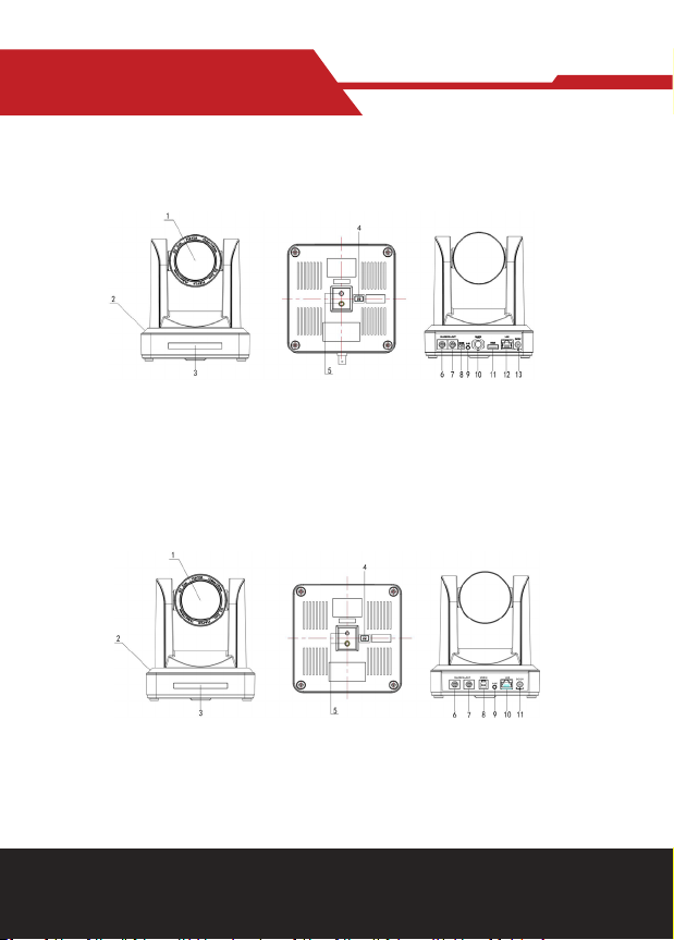
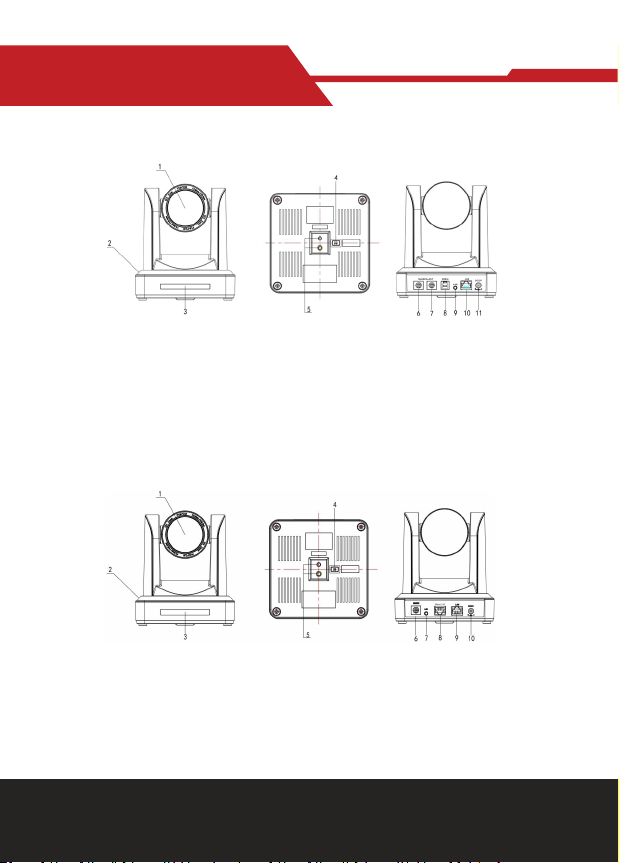
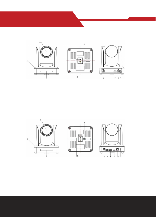
1.1 Camera Interface Explanation............................................................................................................... 5
1.2 Power-on Initial Conguration.............................................................................................................. 8
1.3 Video Output........................................................................................................................................... 8
2. Product Overview.................................................................................................................................... 11
2.1 Product Introduction............................................................................................................................... 11
2.1.1 Product Model...................................................................................................................................... 11
2.1.2 Dimension………………………………............................................................................................................ 12
2.1.3 Accessory.............................................................................................................................................. 12
2.2 Main Features.......................................................................................................................................... 12
2.2.1 Camera Performance........................................................................................................................... 12
2.2.2 Network Performance......................................................................................................................... 13
2.3 Technical Specication........................................................................................................................... 13
2.4 Interface Instruction............................................................................................................................... 15
2.4.1 External Interface................................................................................................................................ 15
2.4.2 Bottom Dial Switch.............................................................................................................................. 17
2.4.3 RS-232 interface.................................................................................................................................. 18
3. Application Instruction........................................................................................................................... 20
3.1 Video Output........................................................................................................................................... 20
3.1.1 Power-On Initial Conguration........................................................................................................... 20
3.1.2 Video Output........................................................................................................................................ 20
3.2 Remote Controller................................................................................................................................... 21
3.2.1 Keys Introduction
3.2.2 Applications.......................................................................................................................................... 21
3.3 Menu Setting........................................................................................................................................... 23
3.3.1 Main menu............................................................................................................................................ 23
3.3.2 System setting..................................................................................................................................... 24
3.3.3 Camera setting..................................................................................................................................... 24
3.3.4 P/T/Z..................................................................................................................................................... 27
3.3.5 Video Format........................................................................................................................................ 28
3.3.6 Version.................................................................................................................................................. 28
3.3.7 Restore Default.................................................................................................................................... 29
4. Network Connection............................................................................................................................... 29
4.1 Connecting Mode.................................................................................................................................... 29
4.2 IE Log In.................................................................................................................................................... 32
4.2.1 Web Client............................................................................................................................................ 32
4.2.2 Preview.................................................................................................................................................. 32
4.2.3 Playback................................................................................................................................................ 32
4.2.4 Conguration........................................................................................................................................ 33
4.2.5 Video Conguration............................................................................................................................. 34

www.hameco.eu
HV-51 User Manual
hameco
4
4.2.6 Network Conguration....................................................................................................................... 37
4.2.7 System Conguration.......................................................................................................................... 38
4.2.8 Logout................................................................................................................................................... 39
4.2.9 Wireless Network................................................................................................................................ 40
5. Serial Communication Control............................................................................................................... 40
5.1 VISCA Protocol List................................................................................................................................. 40
5.1.1 Camera Return Command.................................................................................................................. 40
5.1.2 Camera Control Command.................................................................................................................. 41
5.1.3 Inquiry Command................................................................................................................................. 46
5.2 Pelco-D Protocol Command List............................................................................................................ 49
5.3 Pelco-P Protocol Command List............................................................................................................ 50
6. Camera Maintenance and Troubleshooting....................................................................................... 51
6.1 Camera Maintenance.............................................................................................................................. 51
6.2 Troubleshooting...................................................................................................................................... 51
Product Disposal.......................................................................................................................................... 52

www.hameco.eu
HV-51 User Manual
hameco
5
1. FAST INSTALLATION
1.1 Camera Interface Explanation
1. Camera Lens
2. Camera Base
3. Remote Controller Receiver Light
4. Bottom Dial Switch
5. Tripod Screw Hole
6. RS232 Control Interface (input )
7. RS232 Control Interface (output )
8. RS485 Input (left +,right-)
9. Audio Input Interface
10. 3G-SDI interface
11. HDMI Interface
12. 10/100M Network Interface
13. DC12V Input Power Supply Socket
1. Camera Lens
2. Camera Base
3. Remote Controller Receiver Light
4. Bottom Dial Switch
5. Tripod Screw Hole
6. RS232 Control Interface (input )
7. RS232 Control Interface (output )
8. USB3.0 interface
9. Audio Input Interface
10. 10/100M Network Interface
11. DC12V Input Power Supply Socket
Figure 1.1 Interface of ST (standard) Series
Figure 1.2 Interface of U3 (USB3.0) Series

www.hameco.eu
HV-51 User Manual
hameco
6
Figure 1.4 Interface of HD BaseT Series
1. Camera Lens
2. Camera Base
3. Remote Controller Receiver Light
4. Bottom Dial Switch
5. Tripod Screw Hole
6. RS232 Control Interface (input )
1. Camera Lens
2. Camera Base
3. Remote Controller Receiver Light
4. Tripod Screw Hole
5. Bottom Dial Switch
7. RS232 Control Interface (output )
8. USB2.0 interface
9. Audio Input Interface
10. 10/100M Network Interface
11. DC12V Input Power Supply Socket
6. RS232(IN)
7. Audio-in
8. HDBaseT
9. Lan
10.Power Supply
Figure 1.3 Interface of U2 (USB2.0) Series

www.hameco.eu
HV-51 User Manual
hameco
7
1.5 HM Model(HDMI Output)
1.6 U2U3 (USB2.0, USB3.0, HDMI Output)
1. Camera Lens
2. Camera Base
3. Remote Controller Receiver Light
4. Tripod Screw Hole
5. Bottom Dial Switch
1. Camera Lens
2. Camera Base
3. Remote Controller Receiver Light
4. Bottom Dial Switch
5. Tripod Screw Hole
6. RS232(IN)
6. RS232(IN)
7. HDMI Output
8. Lan
9.Power Supply
7. USB 2.0
8. USB 3.0
9.HDMI Output
10.LAN
11.Power Supply
Note: ST model is standard interface, U3 model is USB3.0 interface, U2 model has USB2.0 interface, HD
model has HD BaseT interface. Users should read the manual according to the specic model.

www.hameco.eu
HV-51 User Manual
hameco
8
1.2 Power on initial conguration
1) Power on: Connect DC12V power supply adapter with power supply socket.
2) Initial conguration: Power on with power indicator light on and remote control receiver light blink-
ing, camera head moves from bottom left to the bottom, and then goes to the HOME position (inter-
mediate position of both horizontal and vertical ),while the camera module stretches. When remote
control receiver light stops blinking, the self-check is complete.
Note: If you set preset 0, when the Power on self-test is completed, the camera automatically moves
to the preset 0 position.
1.3 Video Output
This series has a variety of video outputs; ST models have video output from LAN, HDMI and 3G-SDI,
U3 models from LAN and USB3.0 which are compatible with USB2.0, and U2 models from LAN and
USB2.0. HD models from LAN and HD-BaseT, HM Models from HDMI and Lan; U2U3 models from LAN/
USB2.0/USB3.0/HDMI ports.
1) Video Output from LAN
a. Network Cable Connection Port: ST Model--No.12 in Figure1.1; U3 Model--No. 8 in Figure1.2; U2
Model--No.8 in Figure 1.3.HD Model--No.9 in Figure1.5; U2U3 Model --No.10 in Figure1.6.
b. Webpage Login: Open your browser and enter 192.168.5.163 in the address bar (factory default);
press Enter to enter into the login page; click on the “player is not installed, please download and in-
stall!” and follow the installation steps for installation.
Then enter the user name admin and password admin (factory default); press Enter to enter into the
preview page, users can carry out PTZ control, video recording, playback, conguration and other op-
erations.
2) HDMI Video Output
a. HDMI Video Cable Connection: ST models refer to No.11 in Figure1.1. U2U3 models refer to No.9 in
Figure1.6.
b. Connect the camera and the monitor via HDMII video cable; video output is available after camera
self-test.
3) 3G-SDI Video Output
a. 3G-SDI video cable connection: ST models refer to No.10 in Figure1.1.
b. Connect the camera and the monitor via 3G-SDI video cable; video output is available after camera
self-test.
4) USB3.0 video output
a. USB3.0 video cable connection: U3 models refer to No.7 in gure1.2.U2U3 models refer to No.8 in
Figure1.6.
b. Connect the camera and the monitor via USB3.0 video cable, open video display software, select
image device, and then video
output will be available.

www.hameco.eu
HV-51 User Manual
hameco
9
5) USB3.0 compatible with USB2.0 output
a. USB3.0 video cable connection: U3 models refer to No.7 in Figure1. 2.U2U3 models refer to No.8 in
Figure1.6.
b. Connect the camera and the monitor via USB3.0 video cable, open video display software, select
image device, and then video output will be available.
6) USB2.0 video output
a. USB2.0 video cable connection: U2 models refer to No.7 in Figure1. 3.U2U3 models refer to No.7 in
Figure1.6.
b. Connect the camera and the monitor via USB2.0 video cable, open video display software, select
image device, and then video output will be available.
7) HDBaseT video output
a. IP cable connect: HD model please refer to gure 1.0 No.8.
b. Connect the device, HD BaseT signal receiving device and the display together properly through the
network cable and video cable. Image will be displayed after the device fhas nished.
HD BaseT signal receiving device : HD BaseT adapter box, input HD BaseT signal, output HDMI signal.
Note: USB2.0 output and USB3.0 output is the same interface.
1.4 Bracket mount
Note: Bracket can only be wall mounted or mounted upside-down on a template and concrete wall,
but cannot be installed on plasterboard.
ww

www.hameco.eu
HV-51 User Manual
hameco
10
2. Upside-down mount step

www.hameco.eu
HV-51 User Manual
hameco
11
2. PRODUCT OVERVIEW
2.1.1 Product Model
There are four main series according to dierent video formats, lens optical zooms, output interfaces
and remote control modes.
IR ---IR Remote Control
WR---Wireless Remote Control
ST---Standard Interface (5G Wi function optional)
U2---USB2.0 Interface
U3---USB 3.0 Interface
HD---HD BaseT
HM-- HDMI
U2U3 - USB3.0, USB2.0, HDMI
05---05x Optical Zoom Lens
10---10 x Optical Zoom Lens
12---12x Optical Zoom Lens
20---20x Optical Zoom Lens
S---1080P60 Downward Compatibility
(Support ST/HD/U3/U2U3 Interface)
M---1080P30Downward Compatibility
HV-51
Please refer to the corresponding features in this manual.
Note: 5Gwi is optional for ST (standard) series only.
2.1.2 Dimension

www.hameco.eu
HV-51 User Manual
hameco
12
2.1.3 Accessories
Please refer to the corresponding features in this manual.
Model
NO.
Congur
ation ST/HD/HM Series U3 Series U2 Series U2U3 Series
Accessories
Standard
Power adapter 1piece
RS232 cable 1
piece
USB3.0 cable 1
piece
USB2.0 cable 1
piece
USB3.0 and
USB2.0 cables
User manual 1
Double-side glue shim 4pcs
Warranty card 1 piece
Optional
IR Remote
control piece
IR Remote control
or wireless controller piece
Wireless controller 1 piece
Wall mounting bracket (optional)
Upside-down mounting bracket (optional)
Cascade cable
USB2.0 Video cable: If a USB2.0 cable is needed to provide power but not a power adapter, USB2.0 Video cable with two
ports is needed,the red port is for power supply and black port for transmitting USB video signals. If using a power adapter,
the general USB2.0 video cable without power supply function is ne.
2.2 Main Features
2.2.1 Camera Performance
This series camera oers perfect functions, superior performance and rich interfaces. The features
include advanced ISP processing algorithms to provide vivid images with a strong sense of depth, high
resolution and fantastic color rendition. It supports H.265/H.264 encoding which makes motion video
uent and clear even with less than ideal bandwidth conditions.
1.Superb High-denition Image: It employs 1/2.8 inch high quality CMOS sensor. Resolution is up to
1920x1080 with frame rate up to 60 fps.
2.Various Optical Zoom Lens: It has 5X/10X/12X/20X optical zoom lens for options. The 5X zoom lens
has a 80.9 ° wide view angle without distortion.
3. Leading Auto Focus Technology: Leading auto focus algorithm makes the lens fast, accurate and
provides stable auto-focusing.
4. Low Noise and High SNR: Low Noise CMOS eectively ensure high SNR of camera video. Advanced
2D/3D noise reduction technology is also used to further reduce the noise, while ensuring image sharp-
ness.
5. Quiet PTZ: By adopting a high accuracy step driving motor mechanism, it works extremely quietly
and moves smoothly and quickly to the designated position.
6. Multi-Format Video Outputs: supports HDMI,3G-SDI, USB, wired LAN and wireless LAN interfaces
The 3G-SDI is available for 100m transmission at 1080p60 format.

www.hameco.eu
HV-51 User Manual
hameco
13
7.Multiple Remote Controls: There is an IR remote and 2.4G wireless remote for options. The 2.4G
wireless remote controller will not be aected by angle, distance or IR interference. Supports transpar-
ent transmission functions.
8.Low-power Sleep Function: Supports low-power sleep/wake up, the consumption is lower than
500mW under sleep mode
9.Support Multiple Control Protocol: Supports VISCA, PELCO-D, PELCO-P protocols which can also be
automatically recognized. Supports VISCA control protocol through IP port.
10.RS-232 Cascade Function: ST series supports RS-232 cascade function which is convenient for in-
stalling.
11.255 Presets Positions: Up to 255 presets (10 presets with remote).
12.Wide Application: Tele-education, capturing lectures, webcasting, video-conferencing, tele-train-
ing, tele-medicine, interrogation and emergency command systems.
2.2.2 Network performance
1. Audio Input Interface: Supports 16000,32000,44100,48000 sampling frequency and AAC, MP3,
PCM audio coding.
2. Multiple Audio/Video Compression: Supports H.264/H.265 video compression; AAC,MP3 and PCM
audio compression; Supports compression of resolution up to 1920x1080 with frame up to 60 fps and
2 channel 1920x1080p with 30 fps compression.
3. Multiple network protocols : Supports ONVIF,RTSP,RTMP protocols and RTMP push modes, easy to
link streaming media server (Wowza, FMS)
4. 5G WIFI function: If the product contains a 5G wi module, you can set up a wireless wi connection
in a webpage, the specic conguration is described in detail on the page on web conguration.
2.3 Technical Specications
Model 5X 10X 15X 20x
Camera Parameter
Sensor 1/2.8 inch high quality HD CMOS sensor
Eective Pixels 16: 9 2.07 megapixel
Video Format
HDMI/SDI/HDBaseT video format
1080P60/50/30/25/59.94/29.97;1080I60/50/59.94;720P60/50/30/25/59.94/29.97
U3 interface video format
1)U3:1920X1080P60/50/30/25;1280X720P60/50/30/25;960X540P30;640X-
360P30;640X480P30;3
52X288P30;960X540P30;
2)U3 compatible with U2: 960X540P30; 640X360P30; 1280X720P10/15; 720X576P50;
720X480P60; 640X480P30; 352X288P30.
U2 interface video format
176x144/320x240/320x180/352x288/640x480/720x576/640x360/800X600/960X-
540/1024X576/
1024X768/1600X896/1920X1080/1280X720;P30/25/20/15/10/5
Optical Zoom 5X
f;3.6;18mm
10X
f;4.7;47mm
12X
f;3.9;46.1mm
20X
f;5.2;98mm
View Angle 16.43°;tele; 80.9°
;wide;
6.43°;tele; 60.9°
;wide;
6.3°;tele;
72.5°;wide;
3.2°;tele;
55.8°;wide;

www.hameco.eu
HV-51 User Manual
hameco
14
Model 5X 10X 15X 20x
Camera Parameter
AV F1.6 – F3.0 F1.6 – F3.0 F1.8 – F2.4 F1.5 – F3.0
Digital Zoom 10X
Minimum
Illumination 0.5Lux (F1.8, AGC ON)
DNR 2D & 3D DNR
White Balance Auto / Manual/ One Push/ 3000K/
White Balance Auto / Manual/ One Push/ 3000K/ 4000K/5000K/6500K
Focus Auto/Manual
Aperture Auto/Manual
Electronic Shutter Auto/Manual
BLC ON/OFF
WDR OFF/ Dynamic level adjustment
Video adjustment Brightness, Color, Saturation, Contrast, Sharpness, B/W mode, Gamma curve
SNR >55dB
Input/Output Interface
Video Interfaces
UV510A-05/10/12/20-ST Model;HDMI, 3G-SDI, LAN, Audio-in
UV510A-05/10/12/20-U2 Model;USB2.0(power supply available) LAN, Audio-in
UV510A-05/10/12/20-U3 Model;USB3.0(power supply available)LAN, Audio-in
UV510A-05/10/12/20-HD Model;HDBaseT(POE), LAN, Audio-in
UV510A-05/10/12/20-HD Model;HDMI, LAN, RS232(in)
UV510A-05/10/12/20-U2U3 Model;USB2.0, USB3.0, HDMI, LAN, RS232;input;
Image code stream Double streams outputs simultaneously
Video format Compression H.264, H.265
Control Signal Interface RS-232 Ring through RS232 output, RS-485
Control Protocol VISCA/Pelco-D/Pelco-P; Baud Rate: 115200/9600/4800/2400bps
Audio input Interface Double track 3.5mm linear input;
Audio Compression Format AAC/MP3/PMC Audio compression
HD IP Interface 100M IP port(100BASE-TX); 5G WiFi (optional), support IP Visca control
protocol
Network Protocol RTSP/RTMP,ONVIF
Power Interface HEC3800 outlet (DC12V)

www.hameco.eu
HV-51 User Manual
hameco
15
PTZ Parameter
Pan Rotation ±170°
Tilt Rotation -30°;+90°
Pan Control Speed 0.1 -180°/sec
Tilt Control Speed 0.1-80°/sec
Preset Speed Pan 60°/sec, Tilt: 30°/sec
Preset Number 255 presets (10 presets by remote controller)
Other Parameter
Supply Adapter AC110V-AC220V to DC12V/2A
Input Voltage DC12V±10%
Input Current 1A(Max)
Consumption 12W (Max)
Store Temperature -10; to +60;
Store Humidity 20% - 95%
Working Temperature -10; to +50;
Working Humidity 20%--80%
Dimension 150mmX150mmX167.5mm
Weight 1.4KG
Working Environment Indoor
Remote Operation (IP) Remote Upgrade, Reboot and Reset
Accessory Power Supply,; RS232 Control Cable,;USB3.0 Cable;(U3 Model),;;USB2.0 Cable;
(U2 Model), Remoter;Manual;Warranty card
Optional Accessory Bracket
2.4 Interface Instructions
2.4.1 External Interface
1) External interface of ST models: RS232 Input /Output, RS485 Input, Audio Input,3G-SDI Output,
HDMI Output, LAN, DC12V
Power Interface.

www.hameco.eu
HV-51 User Manual
hameco
16
2) External interface of U3 model:
Audio Input, USB 3.0 Output, LAN, DC12V Power Interface.
3) External interface of U2 model:
Audio Input, USB 2.0 Output, LAN, DC12V Power Interface.

www.hameco.eu
HV-51 User Manual
hameco
17
5. Image Setting
Move the pointer to IMAGE in the Menu, click;HOME;and enter the (IMAGE) as follows,
4) External interface of HD model:
Audio Input, HD Baset Output, LAN, DC12V Power Interface.
4) E5) External interface of U2U3 model:
RS232 input, USB3.0, USB2.0, HDMI, LAN, DC12V power interface.
2.4.2 Bottom Dial Switch
ST model , U3 model and U2 model Bottom Dial Switch diagram shown in Figure 2.6 and 2.7:
ST/U2/HD model: two DIP switches are set to ON or OFF to select dierent modes of operation as shown in Table 2.2
No. SW1 SW2 Explanation
1 OFF ON Working mode
2 ON OFF Updating mode
No. SW2 SW1 Explanation
1 ON OFF Working mode
2 ON ON USB3.0 Software Upgrade Mode
3 OFF ON ARM Software Upgrade Mode
Note: Working mode can be applicable for web upgrade.

www.hameco.eu
HV-51 User Manual
hameco
18
2.4.3 RS-232 Interface
1) ST model RS-232C interface specication as shown below
2) RS-232 Mini-DIN 8-pin Port Denition2.4.3 RS-232 Interface
Computer or keyboard and camera connection method
Camera
1.DTR
2.DSR
3.TXD
4.GND
5.RXD
6.GND
7.IR OUT
8.NC
WidowsDB-91.
1.DCD
2.DSR
3.TXD
4.GND
5.RXD
6.GND
7.IR OUT
8.NC
No. Port Denition
1 DTR Data Terminal Ready
2 DSR Data Set Ready
3 TXD Transmit Data
4 GND System Ground
5 RXD Receive Data
6 GND System Ground
7IR OUT IR Commander Signal
8NC No Connection

www.hameco.eu
HV-51 User Manual
hameco
19
3) RS232 (DB9) Port Denition
4) VISCA networking as shown below:
No. Port Denition
1 DCD Data Carrier Detect
2 RXD Receive Data
3 TXD Transmit Data
4 DTR Data Terminal Ready
5 GND System Ground
6 DSR Data Set Ready
7 RTS Request to Send
8CTS Clear to Send
9 RI Ring Indicator
Camera cascade connection method
Camera 1
1.DTR
2.DSR
3.TXD
4.GND
5.RXD
6.GND
7.IR OUT
8.NC
Camera 2
1.DCD
2.DSR
3.TXD
4.GND
5.RXD
6.GND
7.OPEN
8.OPEN
Note: ST model has RS232 input and output interface, so you can cascade as above. It won’t work for the U3 model
since the U3 model only has an RS232 input interface.

www.hameco.eu
HV-51 User Manual
hameco
20
3. APPLICATION INSTRUCTIONS
3.1 Video Output
3.1.1 Power-On Initial Conguration
Connecting the power, camera will start initial conguration the R indicator light will be ashing. When
the camera returns to the HOME position (middle position for P/T),and lens nishes zooming n/out, the
auto-testing is complete. IR LED will also also stop ashing. If the preset 0 is set, camera will rotate to
the 0 preset position after initial conguration.
3.1.2 Video Output
Connect to the video output cable: the user selects the output mode according to the machine model.
Figure 1.4.1 is for your reference (output interface introduction for each product)
1) network output: connect this product and your computer through the network cable then open the
browser, enter the camera IP address (factory default 192.168.5.163) in the address bar, in the login
page input a user name and password (factory default are “admin”) . Finally, enter the preview page,
and the image comes out.
(Note: If you forget your user name, password, IP address, you can manually restore the default with
the remote control key combination * #)
2)3G-SDI output or DVI (HDMI) output: Connect the monitor with the corresponding video output
interface, then the monitor will output the image.
3)USB3.0 output: Connect this product with computer USB3.0 interface (blue),open the Device Manag-
er to see whether there is an image device and whether the Universal Serial Bus controllers recognize
USB3.0 device. After being properly identied, open the software, choose the image device and then
it will output the image.
4)USB3.0 compatible with USB2.0 output: Connect this product with computer USB2.0 interface
(black),open the Device Manager to see whether there is an image device and whether the Universal
Serial Bus controllers recognize USB3.0 device. After proper identication, open the software, choose
the image device and then it will output the image.
This manual suits for next models
4
Table of contents