Hamilton XE Quick start guide

XE VALIDATOR
Operational Manual
Document #101-0079 1 11/30/17

Document #101-0079 2 11/30/17
TABLE OF CONTENTS
I. INTRODUCTION............................................................................................................................ 4
II. SWITCH SETTINGS....................................................................................................................... 5
III. ELECTRICAL CONNECTIONS....................................................................................................... 7
IV. TESTING...................................................................................................................................... 9
V. MAINTENANCE............................................................................................................................. 10
• Monthly (depending on use).................................................................................................... 10
• Yearly...................................................................................................................................... 10
• XE Validator Calibrations.......................................................................................................... 11
To calibrate the optics.......................................................................................................... 11
To calibrate the side scans................................................................................................... 11
VI. PARTS......................................................................................................................................... 12
VII. ERROR CODES .......................................................................................................................... 13
• Troubleshooting ..................................................................................................................... 14
APPENDIX A ................................................................................................................................... 20
• XE Validator Dimensions ......................................................................................................... 20

Document #101-0079 3 11/30/17
This manual will enable the operator to complete basic maintenance, identify error codes, and perform basic
troubleshooting.
A diagram of the validator dimensions is provided to assist operators in customizing the validator to individual
needs.
There are no user serviceable parts inside the validator. Further technical assistance can be obtained by
calling (800) 837-5561 or (419) 867-4858.
When calling for service, it is important to have the model and serial number readily available. Please take
the time to record this number in the space provided.
VALIDATOR MODEL & SERIAL #_________________________________________________
ABOUT THIS MANUAL

Document #101-0079 4 11/30/17
The XE VALIDATOR is an optical reading bill acceptor capable of validating one, five, ten or twenty dollar
bills. The XE can also accept the patented Hamilton paper Tokenotes®.
NOTE: Tokenotes®can be interchanged between the HV-X, XE and
STA Validators, but CANNOT be interchanged with previous validators.
Please include the model and serial number of the validator when ordering Tokenotes®.
FEATURES OF THE XE INCLUDE:
• Bill acceptance in both directions.
• Optical reading of bills.
• Tokenote®acceptance.
• Self-diagnostics.
• The ability to clear jammed bills.
• Operates with a separating stacker in certain changers
An upgradeable EPROM allows the software to be updated if new software becomes available.
I. INTRODUCTION

Document #101-0079 5 11/30/17
DIP SWITCH SETTINGS
Switch # OFF ON
1 Normal Operating Mode Diagnostic Mode
2 Accept Tokenotes®Reject Tokenotes®
3 Controller Runs Stacker Validator Runs Stacker
4 Not Using Dual Stacker Dual Stacker Being Used
5 Accepts in Both Directions Black Seal First
6 For HOPPER type machines
# of $1 RELAY pulses - 1 for $1
# of $5 RELAY pulses - 1 for $5
2 for $10
4 for $20
For TUBE type machines # of
$1 RELAY pulses.
1 pulse per dollar.
7 Accept $1 Reject $1
8 Accept $5 Reject $5
9 Accept $10 Reject $10
10 Accept $20 Reject $20
When programming Tokenotes®with the XE, all switches need to be set to the “ON” position. The switches
should be turned “ON” from BOTTOM to TOP, starting with switch #10.
When programming is complete, the switches should be turned “OFF” from TOP to BOTTOM, starting with
switch #1. This will prevent accidental entry into any diagnostic modes. It is possible to get error codes and
total reject by entering certain diagnostic modes. Cycling power will clear this diagnostic mode.
Switch #1: Switch #1 should ALWAYS be in the OFF position. The validator will not function properly
otherwise.
Switch #2: Switch #2 should be in the ON position unless the new Hamilton Tokenotes®are being
used. If they are being used, this switch should be moved to the OFF position.
When the #2 switch is ON, the validator rejects Tokenotes®already programmed in.
Switch #3: Switch #3 selects the source of stacker control signals when operating in pulse
communications mode. In serial communications mode, this switch is ignored. In nearly
all situations, this switch should be set to off.
Switch #4: Switch #4 should be in the OFF position unless the Hamilton Dual Stacker is being
used.
II. SWITCH SETTINGS

Document #101-0079 6 11/30/17
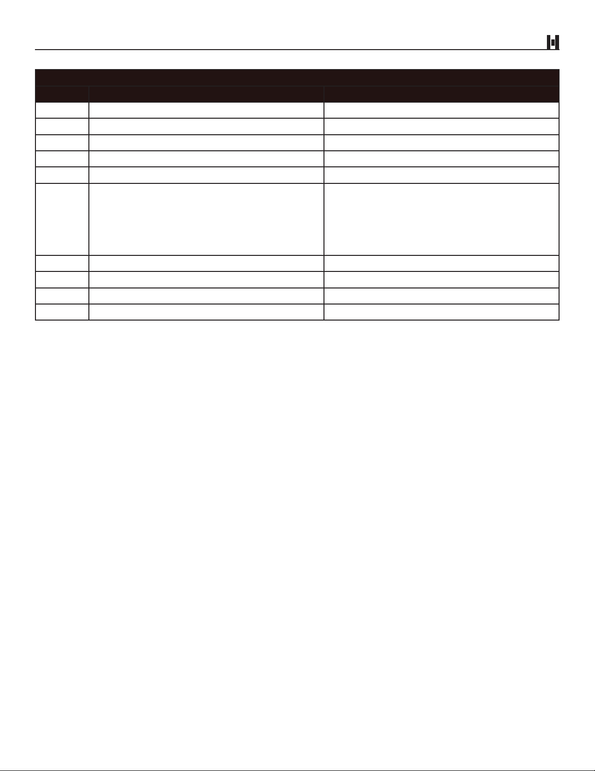
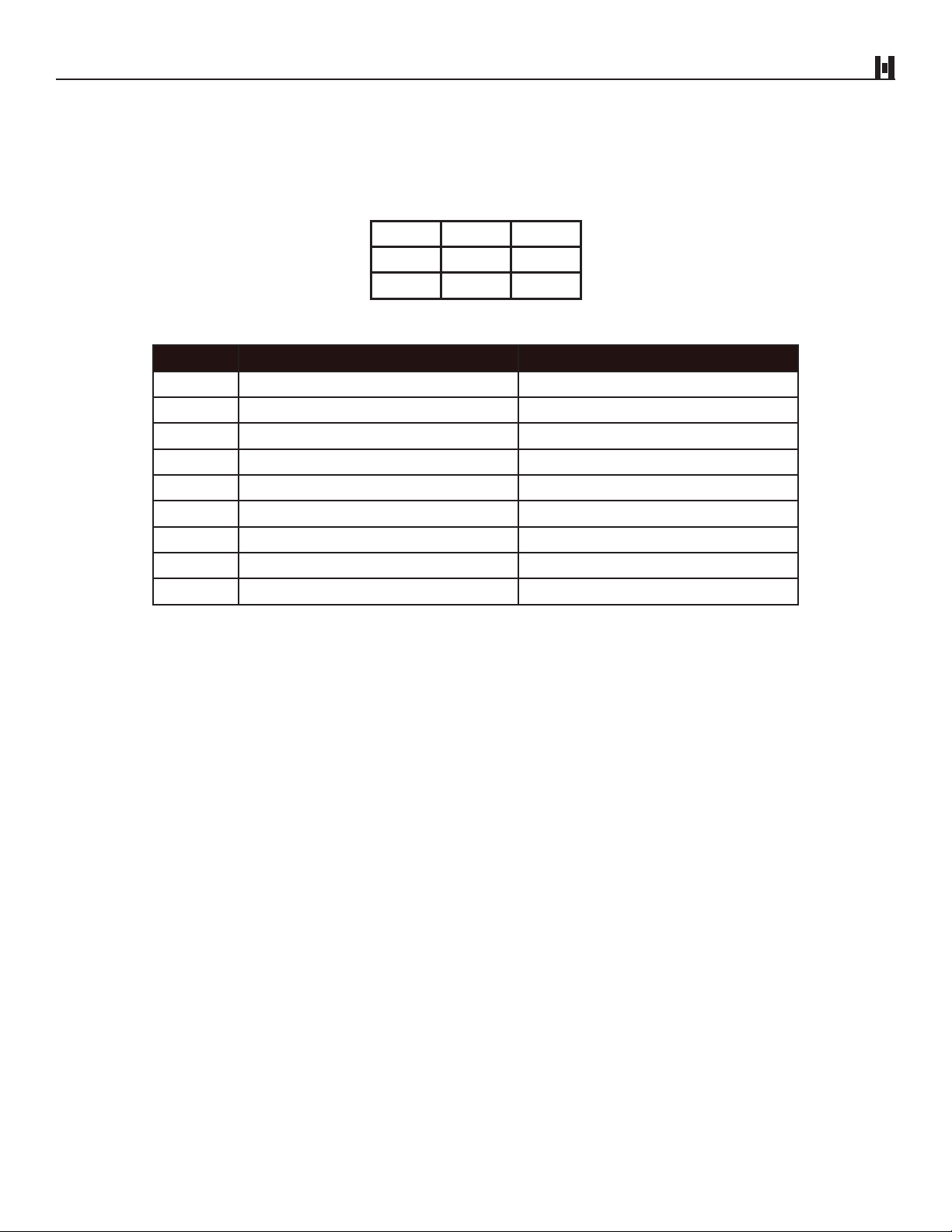
Switch #5: Switch #5 selects which direction the validator will accept an inserted bill. If this switch
is OFF, the validator will accept bills face up in either direction. If this switch is ON, the
validator will only accept bills face up and the end with the black seal inserted first.
Switch #6: Switch #6 selects how the validator signals the dispensing equipment after accepting a
bill. If this switch is OFF, the validator will activate the $1 Relay once for an accepted $1
bill, the $5 Relay once for an accepted $5 bill, the $5 Relay twice for an accepted $10
bill, and the $5 Relay four times for an accepted $20 bill.
If switch #6 is ON, the Validator will activate the $1 Relay once for an accepted $1 bill,
the $1 Relay five times for an accepted $5 bill, the $1 Relay ten times for an accepted
$10 bill, and the $1 relay twenty times for an accepted $20 bill.
SWITCH #6 DOES NOT WORK WITH TUBE TYPE CHANGERS.
Switch #7: Switch #7 selects whether the validator will accept or reject $1 bills. If the switch is in
the OFF position, the validator will accept $1 bills. If the switch is ON, the validator will
reject $1 bills.
Switch #8: Switch #8 selects whether the validator will accept or reject $5 bills. If the switch is in
the OFF position, the validator will accept $5 bills. If the switch is ON, the validator will
reject all $5 bills.
Switch #9: Switch #9 selects whether the Validator will accept or reject $10 bills. If the switch is in
the OFF position, the validator will accept $10 bills. If the switch is ON, the validator will
reject all $10 bills.
Switch #10: Switch #10 selects whether the Validator will accept or reject $20 bills. If the switch is
in the OFF position, the validator will accept $20 bills. If the switch is ON, the validator
will reject all $20 bills.
II. SWITCH SETTINGS

Document #101-0079 7 11/30/17
The electrical connections are made via a 9-pin connector located on the rear panel of the unit. The following
diagram and chart have been included for custom installation.
9-PIN CONNECTOR
EXTERNAL VIEW
321
654
987
WIRE VIEW
PIN # COLOR NAME
1 Blue Enable
2 White 120VAC Neutral
3 Brown Vend Common
4 N/A N/A
5 N/A N/A
6 Green Ground
7 White/Blue $1 Vend Contact Closure
8 White/Brown $5 Vend Contact Closure
9 Black 120VAC Hot
III. ELECTRICAL CONNECTIONS

Document #101-0079 8 11/30/17
When used in serial communications mode, serial data and stacker control signals are found on the 9-pin
connector of the display board. The following diagram and chart defines the available signals.
PIN # COLOR NAME
1 DIAG_TXD
2 Brown COM
3 DIAG_RXD
4 V5.0
5 Pink SM BUS _+
6 Lt Blue SM BUS_+
7 Yellow HOME
8 Black DOWN
9 Blue STK_DC
PIN 1
Diagnostic Header Pin 1 Location
with Smart Display Board
III. ELECTRICAL CONNECTIONS

Document #101-0079 9 11/30/17
IV. TESTING
After installation, a short test may be performed to verify correct installation.
For testing, be sure switch #1 is OFF. Be sure to test with a quantity of bills.
TEST DESIRED RESULT
Turn on unit Decimal point flashing
Insert bill Payout proper change for each bill type
Should this unit fail to operate accordingly, check for an error code and refer to the Troubleshooting
section of this manual.

Document #101-0079 10 11/30/17
MONTHLY - Depending on use
1. The platen assembly should be opened and cleaned regularly
2. To open the platen assembly:
• Unplug the changer
• Disconnect the 9-pin plug
• Remove the validator from the holder
• Loosen the 2 thumbscrews on both sides of the validator
• Carefully lift to open from the bill insert end of the validator
3. Clean rollers, heads, belts, and sensors with cotton swabs and rubbing alcohol
4. Close the platen assembly and re-tighten the LATCH STUDS. Loose LATCH STUDS may cause false error
codes.
YEARLY
The XE Validator should be serviced annually to maintain maximum performance.
THIS WORK SHOULD ONLY BE DONE BY A TRAINED TECHNICIAN.
V. MAINTENANCE

Document #101-0079 11 11/30/17
XE VALIDATOR CALIBRATIONS
To calibrate the optics:
1. Power up the validator
*Validator must be in its normal operating position
2. Turn all switches to the OFF position
3. Set switches #8 and #1 to the on position
• Switches must be set in that order
• A “0” should appear on the display
4. Take a clean piece of white copier paper and cut it to the size of a bill (test bill)
5. Run it through the validator, it will step through. This will take about 10 seconds.
6. After the test bill is rejected, remove it from the validator. You should end up with a 1 on the display. If it
is a “3” the validator needs to be serviced.
7. Turn OFF switches #1 and #8, in that order
8. Now, turn the switches back to their original positions
9. Optic calibration is complete
To calibrate the side scans:
1. Power up validator
• Validator must be in its normal operating position
2. Turn all switches to the OFF position
3. Set switches #6 and # 1 to the ON position. The display will flash a “9”, then count down to a “1”.
4. Turn OFF switch #1 a dash “-” will show on the display, wait for the decimal point then turn OFF switch
#6.
5. Now, turn the switches back to their original positions
6. Side scan calibration is complete
V. MAINTENANCE

Document #101-0079 12 11/30/17
PARTS LIST
Part # Description Qty
46-8613 O-RING, DRIVE BELT XE 2
46-8594C XE BILL GUIDE COMPLETE ASSM. 1
46-8592 XE DRIVE BELT 1
48-3007 XE LED HARNESS 1
48-3015 XE POWER HARNESS 1
48-3016 XE SENSOR HARNESS 1
99-0014 HV-STEPPER MOTOR 1
102-0206-XX REPROGRAMMED EPROM 1
104-0000 XE PCB POWER/STEPPER MOTOR ASSM. 1
104-0009 XE SIDESCAN PCB ASSM. 1
104-0052 XE TOP SENSOR PCB ASSM. 1
104-0053 XE BOTTOM SENSOR PCB ASSM. 1
104-0104 MAIN & DISPLAY PCB XE ASSM. 1
VI. PARTS

Document #101-0079 13 11/30/17
The XE provides a diagnostic code for most problems. Upon any problem, the error code should be checked
first.
The display is only a single digit; therefore, to obtain the 2-digit error code, the first digit is displayed WITH
THE DECIMAL POINT (5.) and the second digit is displayed WITHOUT THE DECIMAL POINT (3).
The display will continue to flash the 2-digit error code; one digit at a time, until the failure is corrected or
power is removed.
During normal operation only the decimal point should flash. Do not be concerned if one of the segments
flashes once upon power-up or upon passing a valid bill.
The display is only a single digit; therefore, to obtain the 3-digit error code the first digit is displayed WITH
THE DECIMAL POINT (5.) and the second and third digits are displayed WITHOUT THE DECIMAL POINT
(3) (3). The display will continue to flash the 3-digit error code; one digit at a time, until the failure is
corrected or power is removed.
VII. ERROR CODES

Document #101-0079 14 11/30/17
TROUBLESHOOTING
The following troubleshooting guide is for Tokenote®programming errors only.
TROUBLESHOOTING FOR TOKENOTE®PROGRAMMING ERRORS
ERROR PROBLEM POSSIBLE CAUSE POSSIBLE SOLUTION
3.0
3.1 Tokenote® not found • Tokenote® is not stored into
memory
• Program Tokenote® into
memory
3.2 No marker found on
Tokenote®
• Weak Tokenote®
• Weak mag head signal
• If error continues,
return for service with a
sampling of Tokenotes®
3.4
Primary < >
Secondary
• Primary and secondary
Tokenote® signals do not
match
• Clear Tokenote®from
memory and reprogram
• Return for service
3.5 Programming error • Run Tokenote®or training
coupon again
3.6 12 coupon limit reached
• 12 training coupons have
already been stored into
memory
• Clear Tokenote®and
reprogram with a
maximum of 12 training
coupons
3.7 Unable to store Tokenote®-
‘Storage Full’
• Tokenote®storage memory
is full
• Clear out of memory at
least one Tokenote®and
then reprogram in new
Tokenote®
3.8 Serial RAM chip corrupted
• Tokenote®stored, memory
has been corrupted
• Defective PCB
• Clear all Tokenotes®from
memory and reprogram
• Return for service
VII. ERROR CODES

Document #101-0079 15 11/30/17
TROUBLESHOOTING
►Always note the error code before attempting any service or before contacting the manufacturer
The following troubleshooting guide is based on standard bill operation. A separate guide for troubleshooting
Tokenote®errors is on the previous page.
TROUBLESHOOTING FOR STANDARD BILL OPERATION
ERROR PROBLEM POSSIBLE CAUSE POSSIBLE SOLUTION
0.1 Bill allowed, black seal first only • Switch 5 is in the ON
position
0.2 Bill type turned off
• A bill was inserted that is
turned off via switches 7, 8,
9 or 10
0.3 All bill types disabled • Switches for all bill types are
set to the ON position
• Turn switches off for types of
bills to be accepted
0.4 All bill types and Tokenotes®
disabled
• Switches for all bill types are
set to the ON position
• Turn switches off for types of
bills to be accepted
0.5 Escrowed bill declined by
controller
• HTK controller may be
configured to reject this bill
type
• Verify HTK controller
configuration is set to accept
bill type
1/2 of 1 Unit inhibited • No ENABLE signal
• Check controller reset
• Check for open harness
• Return for service
1.2 Secondary head noise too high • Noisy frame, head, or PCB • Clean heads and rollers
• Return for service
1.3 Secondary head • Open head circuit • Return for service
1.4 Primary head noise too high • Noisy frame, head, or PCB • Clean heads and rollers
• Return for service
1.5 Primary head signal • Open head circuit • Return for service
1.6 Rear sensor blocked • Obstruction blocking rear
sensor • Remove obstruction, clean
1.7 Rear sensor blocked • Obstruction blocking rear
sensor • Remove obstruction, clean
1.8 Front sensor blocked • Obstruction blocking front
sensor
• Remove obstruction, clean
sensor, cycle power, reset
controller
2.0 Stacker time-out
• Incorrect controller or
configuration switch setting
• Stacker jam
• Verify that the controller
is a v1.6 or greater, and
configuration switch #6 is
on, cycle power
• Clear jam
• Return for service
VII. ERROR CODES

Document #101-0079 16 11/30/17
TROUBLESHOOTING FOR STANDARD BILL OPERATION (continued)
ERROR PROBLEM POSSIBLE CAUSE POSSIBLE SOLUTION
2.1 Side sensors out of adjustment
• Possible component failure
• Possible misalignment of
sensors
• If this error continues to be
displayed, return for service
2.3 Side sensors out of adjustment • Possible component failure
or vandalism
• If this error continues to be
displayed, return for service
2.4 Side sensors out of adjustment • Possible component failure
or vandalism
• If this error continues to be
displayed, return for service
2.6 Escrow timeout
• Communications lost
between validator and HTK
controller
• Check that all harnesses
are securely plugged into
validator and stacker control
board
4.X Bill validator optic error • Rejected bill
• Sensors dirty
• These errors can be
displayed intermittently on
bill rejects. This is a normal
condition.
• If you continuously get
these errors with total reject
condition, clean the sensors
with a little mild soapy water.
Do not let excess water get
into the validator and do not
use anything abrasive on the
front sensor.
• Check for clogged sensor
• Return for service
5.X Bill validator magnetics error • Rejected bill
• Bill not touching head
• These errors can be
displayed intermittently on
bill rejects. This is a normal
condition.
• If you continuously get
these errors with total reject
condition, check rollers to
ensure a good flat contacting
point between head and
roller is established
• Return for service
6.X Cheating attempt • A cheating attempt has been
detected
• Check inventory, cycle
power to remove error
• Ensure latch studs are
tightened completely
NOTE: Any of these errors ending with a “4” (i.e. 6.X4) may be caused by the sidescans being out of
adjustment.
VII. ERROR CODES

Document #101-0079 17 11/30/17
TROUBLESHOOTING FOR STANDARD BILL OPERATION (continued)
ERROR PROBLEM POSSIBLE CAUSE POSSIBLE SOLUTION
8.0 Low magnetics • Rejected bill
• Bill not touching heads
• These errors can be
displayed intermittently on
bill rejects. This is a normal
condition.
• If you continuously get
these errors with total
reject condition, check
rollers to ensure a good,
flat contacting point
between head and roller is
established.
• Return for Service
8.1 Short bill • The bill inserted was too
short
J Jammed bill
• Will be displayed for 2
minutes if the obstruction
is not removed. After the
2 minutes, either a 1.7 or
1.8 will be displayed for the
blocked sensor.
• Remove obstruction, clean
sensor, cycle power, reset
controller
PTokenote® programming • All switches are turned ON • Turn switches back to
normal positions
VII. ERROR CODES

Document #101-0079 18 11/30/17
With the introduction of the XE Smart Validator capabilities there are five additional diagnostic lights. Their
operation is defined below.
VAL TXD – Validator Transmit LED
This LED gives the status of the Validator transmit line.
• ON = Validator is transmitting a message on the Smart Bus
• OFF = Validator is not transmitting
VAL RXD – Validator Receive LED
This LED gives the status of the Validator receive line
• ON = Validator is receiving a message from the Smart Bus
• OFF = Validator is not receiving
STK RUN – Stacker Run Status LED
This LED shows the status of the Stacker Run control line
• ON = Stacker control line is on, activating Stacker
• OFF = Stacker control line is off, Stacker is not active
STK HOME – Stacker Home Status LED
This LED shows the status of the Stacker Home switch. The operation of this LED depends on the type of Stacker used
(Single/Separating). See table on page 19.
STK DOWN – Stacker Down Status LED
This LED shows the status of the Stacker Down switch. The operation of this LED depends on the type of Stacker used
(Single/Separating). See table on page 19.
Note: since it does not have a Down switch, this status LED will always be ON for Single Stackers.
VAL TXD
VAL RXD
STK RUN
STK HOME
ST
K DOWN
VII. ERROR CODES

Document #101-0079 19 11/30/17
STACKER POSITION SINGLE STACKER SEPARATING STACKER
Home position Home LED = OFF
Down LED = ON
Home LED = ON
Down LED = OFF
Between home and
down position
Home LED = ON
Down LED = ON
Home LED = OFF
Down LED = OFF
Down position Home LED = ON
Down LED = ON
Home LED = ON
Down LED = ON
VII. ERROR CODES

Document #101-0079 20 11/30/17
APPENDIX A - XE VALIDATOR DIMENSIONS
Table of contents
Other Hamilton Bank Note Validator manuals