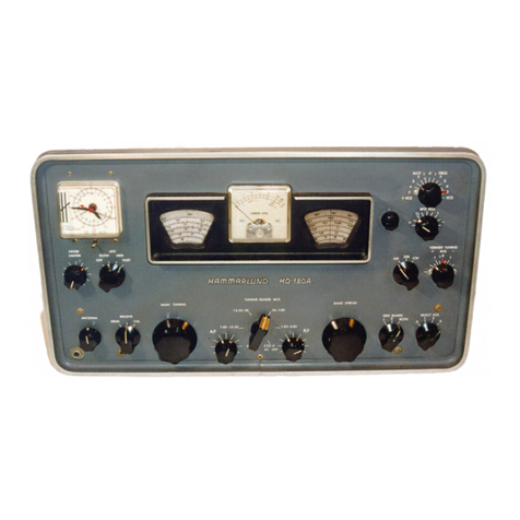
Section I
Paragraphs
1-24
to
1-29
T.O. 31R2-4-101-1
kc.
The
"BEAT
OSc."
control
may be
turned
in
either
direction
on
scale to
provide
the 3-kc
range
for
the re-
ceived
cow
signal.
When
the
"MOD/CW"
switch is
in
the
"MOD"
position, the receiver provides
for
the recep-
tion
of
amplitude-modulated
signals.
When
the
receiver
is to be used
for
the reception
of
afrequency-shift sig-
nal,
the
"MOD/CW"
switch
position
is
dependent
upon
whether
the receiver i-f
output
or
the receiver a-f
output
is
to
be furnished
to
the associated frequency-shift con-
verter
equipment.
When
the receiver i-f
output
is used,
the use
of
the
bfo
provides
optional
receiver
output
for
monitoring
purposes.
When
the receiver a-f
output
is
used,
the
bfo
must
be
in
operation.
When
the receiver
is
to
provide
suppressed-carrier
(single
or
double
side-
band)
reception, the
bfo
is used
to
reinsert the
carrier
at
the receiver.
For
this application, the
"BEAT
OSc."
control
is
set
to a
position
providing
abfo frequency
of
455 ke.
1-24.
The
receiver
"RF
GAIN"
control
(11, figure
3-1)
is adjustable to compensate
for
wide
variations
encountered in the level
of
any carrier received.
To
maintain the receiver a-f
output
constant
within
narrow
limits
for
the
"RF
GAIN"
control
setting
chosen, the
receiver incorporates automatic volume control.
The
re-
ceiver
"AYC/MAN"
switch
(12),
when
set to the
"A
YC"
position, provides this action. Provisions are in-
cluded
in
the receiver
for
a-v-c
operation
even
during
the reception
of
slow-speed
telegraph
signals.
The
"RF
GAIN"
control
is effective in either position
of
the
"A
YC/MAN"
switch.
1-25.
The
receiver
tuning
meter (1, figure
3-1)
pro-
vides a
tuning
indication
for
the desired signal,
when
the
"A
YC/MAN"
switch
(12)
is
set to the
"A
YC"
position.
When
the
"RF
GAIN"
control
(11)
is set
to
its maximum clockwise setting, the meter
top
scale
indication is the ratio
of
the received signal level to a
signal
of
one microvolt, expressed
in
db.
When
the
"METER"
switch
(18)
is
held
in
its depressed
"AF"
position, the meter
bottom
scale indication is the ratio
of
the receiver audio
output
to
the
standard
reference
output
of
six milliwatts, expressed
in
db.
1-26.
OPERATiONAL THEORY.
1-27.
GENERAL.
An
analysis
of
the
operation
of
the
radio
receiver is best evolved by considering the signal
path
through
the receiver r-f, i-f,
and
a-f sections,
into
which the receiver may be considered theoretically sub-
divided.
The
self-contained
power
supply
of
the receiver
is considered separately.
The
simplified block
diagram
(figure
1-2)
indicates
in
block
form
the relationship
between the various sections
of
the receiver.
1-28.
R-F
SECTION.
The
r-f
section
of
the receiver pro-
vides selective circuitry
for
any selected signal
within
the
receiver frequency
range
of
0.54
to
54.0 me.
It
does this
through
the use
of
six sets
of
r-f
tuner
subassemblies
housed in arotary
turret
assembly. Each set is used
for
one
frequency
band
of
the receiver
and
comprises an an-
tenna
r-f tuner, two identical interstage r-f tuners,
and
an
oscillator r-f tuner.
The
"BAND
CHANGE"
switch
(17,
figure
3-1)
provides
for
indenting
the rotary
turret
as-
4
sembly so
that
the
r-f
tuner
subassemblies
for
a
particular
frequency
band
become
part
of
the
r-f
section
of
the re-
ceiver.
The
antenna
and
two-stage r-f
gain
provided
to
the signal assures
that
the signal-plus-noise to noise
ratio
developed in the r-f section·is
high
enough
so
that
even
very weak signals
provide
useful receiver
output.
The
r-f
section preselection assures
that
the
gain
available
to
the signal is greatly
in
excess
of
that
provided
any un-
desired signal. Since the receiver utilizes the principles
of
superheterodyne reception, asignal removed
from
the de-
sired signal by twice the 455-kc
intermediate
frequency
also provides
an
i-f signal acceptable to the i-f section
of
the receiver.
This
image frequency, like any
other
unde-
sired signal, is
greatly
attenuated. However,
for
signals
tuned
in
on
the three
higher
frequency
bands
of
the re-
ceiver, the image frequency
for
an intermediate fre-
quency
of
455 kc
would
be too close
to
the desired
signal.
To
maintain
high
image-rejection ratios, the re-
ceiver provides
for
double
superheterodyne reception
on
these bands.
On
the three lower frequency
bands
(below
7.4
me),
the signal
tuned
in
is
heterodyned
to a455-kc
i-f signal.
On
the three
higher
frequency bands,
it
is
first
heterodyned
to a3955-kc i-f signal, which is
then
heterodyned
to
a455-kc i-f signal.
With
the receiver
"FREQ
CONTROL"
selector switch
(8)
in
its
"YFO"
position, the receiver provides
for
continuously variable
tuning.
When
the switch is
in
one
of
its
"XT
ALS" posi-
tions, the receiver first
heterodyne
variable oscillator is
replaced by afixed-frequency crystal-controlled hetero-
dyne oscillator.
Doing
this results
in
receiver frequency
stability
superior
to
that
attainable
for
variable-
frequency
tuning.
Its use pre-establishes the communica-
tion
channel, even
when
receiving conditions are poor,
without
necessitating atime-consuming search by the
operator.
1-29.
I-F
SECTION.
The
i-f section
of
the receiver in-
corporates the 455-kc i-f amplifier
wherein
practically
all
of
the overall
gain
and
selectivity
of
the receiver is
developed. Also,
it
incorporates the single-double con-
version switch, which assumes its single
or
double
con-
version position
dependent
on
whether
the
rotary
turret
is
indented
respectively
for
one
of
its three
lower
or
three
higher
frequency bands.
For
signals
tuned
in
on
one
of
the three lower frequency bands, the signal has
access
to
the 455-kc i-f amplifier
through
a455-kc i-f
gate.
For
this
condition
the switch
renders
the double-
conversion i-f channel inoperative.
For
signals
tuned
in
on
one
of
the three
higher
frequency bands,
the
signal
reaches the 455-kc i-f amplifier
through
the 3955-kc i-f
double-conversion channel.
For
this cOJ;ldition the switch
renders the 455-kc i-f
gate
inoperative.
The
six choices
of
receiver selectivity
provided
by the
"SELECTIYITY"
switch (22, figure
3-1)
are developed
in
the 455-kc i-f
channel
of
the receiver.
At
the
input
to the 455-kc i-f
amplifier is the 455-kc i-f crystal-filter circuit incorpo-
rated
in
the receiver.
The
use
of
the crystal filter enables
the receiver to
attain
the
three degrees
of
sharp
"XTAL"
selectivity.
The
precise antibacklash
gear-train
tuning
mechanism provides
for
completely accurate resetability
and
calibration accuracy
of
the receiver so
that
maximum
