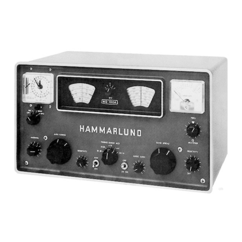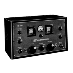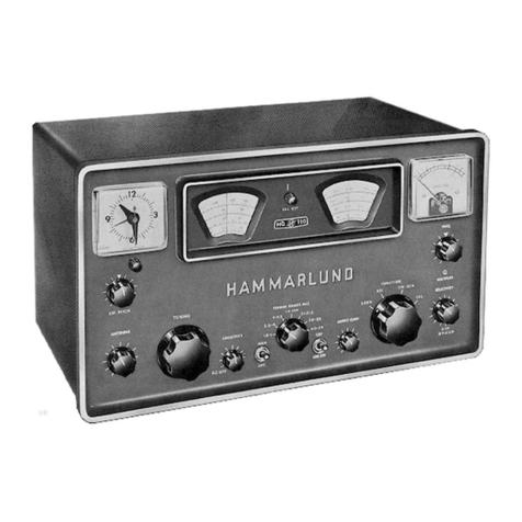
The
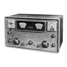
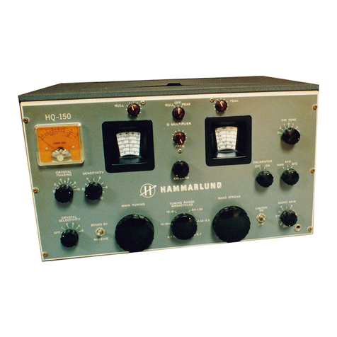
SP-6001~~17is a 20-tube superheterodyne radio communications receiver designed
specifically for diversity reception, The receiver
le
intended for use
a8
either
the "master" or "slave" wit for the reception of
MCW,
CW,
suppressed carrier, or
frequency-shift
signals,
"Master-slave" relationship
is
established by interconnecting two or
=re
receivers. These connections
snay
be
made
between
the
beat-frequency and/or the
heterodyne oscillatora of
eacb
receiver,
or
between
the
receivers
and
sn
externally
co~ectedmsster oscillator
common
to
each.
Frequency drift, after a
15
miqute warm-up,
ranges
between
,001
percent and
,01 percent of frequency, depending on
the
frequency used,
This
is
an
unusual
degree
of
frequency stabilitiy
for
variable tuned
HF
oscillators and closely approaches
crystal stability,
The frequency control unit provides
for
fixed
channel
crystal-controlled opera-
tion on
any
six frequencies
within
the range
from
.75
to
54
megacycles. Front panel
controls permit the selection
of
either
the
normal
high
stability, continuously
variable tuning or fixed frequency operation, For crystal-controlled fixed-channel
operation, it is only necessary
to
set
the
dial to the signal frequency, switch
to
the crystal frequency desired,
and
tune with
the
delta frequency control, Desired
crystals may be purchased on special
order
from
the
Harmnarlund
Manufacturing Colgpany,
The selectivity control provides
3
degrees of crystal and
3
degrees
of non-
crystal selectivity ranging from
sharp
(,2
KC)
to broad (13,O
KC),
The crystal
filter in the
SP-600-~~17
embodies the
same
circuit features
that
have proved so
effective and desirable in Hammwlund
Super-pro
receivers,
Two
stages of radio frequency amplification
are
provided on
all
bands: single!
conversion is used for signal frequencies up to
7,k
megkxcycles,
and
double coaversioq
employing a crystal-controlled oscillator, for signal
frequencies
above
7,4
mega-
cycles.
Four stages of
IF
amplification, detector
and
AVC
rectifier, noise limiter and
meter rectifier, beat frequency oscillator
aud
buffer amplifier,
IF
output,
AF
amplifier
and
output power stage,
are
among the features of the sP-600-~~17,wbich
are discussed fully under separate headings in this manual.
The Audio output circuit is designed for
a
600-ohm
load
or line and is provided
with
a
four-terminal split winding for balanced load operation,
Maximum
power out-
put is approximately
2.0
watts,
The
headphone circuit
when
referred to
aa
8,000-ohm
resistive load provitles signals attenuated approxinately 15
db
below the 600-ohm
power output, Either headphones, loud
speaker
or both may
be
used for reception of
signals,
mereceiver i,f. output or audio-output, connected to
a
suitable frequency-shift
receiver converter
and
associated
teletypewriter, provides for recorded copy
of
a
teletype signal,
A
C1d
signal may be amplitude-modulated
by
aa
external tone
generator connected to
the
receiver, so that
a
steady,
audible (monitoring) tone is
always heard when the transmitter carrier
is
on
the
air, whether
signal
intelligence
is
present, or not,
A
single tuning control of special design permits maximum traveree speed as well
as exceptional operating
ease,
It controls both the
main
and
vernier dials,
The
main dial, in addition to
being
frequency-calibrated, includes
an
arbitrary scale in
