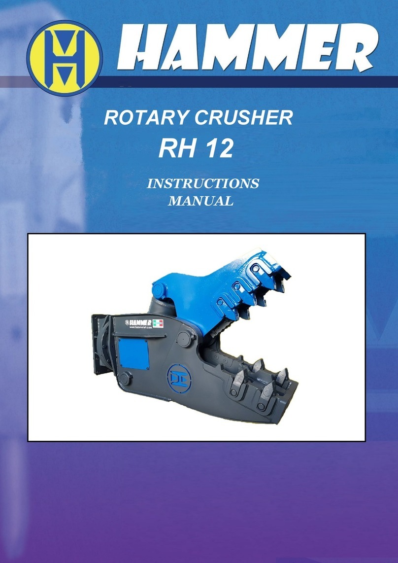
Hammer CR 250 User manual

HYDRAULIC SHEAR
CR 250

2

INDEX
DESCRIPTION OF THE ATTACHMENT _____________________________________________ 6
TECHNICAL SPECIFICATIONS __________________________________________________ 6
OPERATION - USES NOT PERMITTED - RESPONSIBILITY ______________________________ 7
MOVEMENT AND TRANSPORTATION OF THE ATTACHMENT __________________________ 14
ATTACHMENT INSTALLATION _________________________________________________ 14
ASSEMBLY AND DISASSEMBLY OF THE ATTACHMENT _______________________________ 16
START-UP AND USE OF THE ATTACHMENT _______________________________________ 16
CONNECTIONS SPECIFICATIONS: ______________________________________________ 17
MAINTENANCE AND REPAIR __________________________________________________ 18
PIERCING BLADES __________________________________________________________ 20
MOBILE JAW SHIMMING PROCEDURE ___________________________________________ 24
AUTO GUIDE ______________________________________________________________ 27
GUIDE PUCK SHIMMING PROCEDURE ___________________________________________ 28
HARD FACING _____________________________________________________________ 31
GREASING _______________________________________________________________ 32
INFORMATION REGARDING DISMANTLEMENT ____________________________________ 33
SPARE PARTS LIST __________________________________________________________ 33
HYDRAULIC SCHEMATIC _________________________________________________ 34
EXPLODED VIEW AND PARTS LIST ____________________________________________
36 - 46
3

This instruction manual has been designed and organized to permit quick and easy consultation thanks to the
index by topic, with explanatory figures and tables.
This instruction manual must be studied by the owner of the machine, the technical personnel within the
factory, the operators, i.e. all those who use the machine, and the maintenance technician.
The manual is an integral part of the machine and contains information on use, technical characteristics and
instructions for handling, installation, assembly, adjustment and maintenance.
HAMMER technicians are always at the customers disposal and can be contacted by telephone or email
for any additional information required.
This manual:
- must be considered an integral part of the machine until it is demolished;
- must be kept in a suitable easily accessible place
- must be consulted whenever problems or doubts arise concerning operation of the machine;
- must be carefully followed for maintenance operations.
If mislaid, apply for a copy directly from HAMMER SRL.
HAMMER SRL reserves the right to update the machine and instruction manual according to technological
progress and state of the art.
This constitutes no obligation to carry out modifications to the machines that have already been sold.
If the machine is ceded to a third party, it is recommended that the instruction manual follow it.
HAMMER SRL RETAINS ITSELF FREE FROM LIABILITY OF ANY KIND, AND ESPECIALLY FOR:
- improper use of the machine;
- use of the machine by personnel not trained to used it;
- power source defects;
- maintenance defects;
- unauthorized and unforeseen modifications;
- use of spares that are not original or not specific for the model;
- non observance of the instructions
- possible exceptions
The use of the machine for different purposes are to be considered dangerous for the operator and for the
machine. Likewise, modalities of installation and utilization different from that indicated in the present manual
could cause damage to persons and/or to the machine itself.
4

DECLARATION
THE UNDERISGNED HAMMER SRL
(Manufacturer) Via Oleifici dell’Italia Meridionale
Lotto G1
70056 Molfetta (Ba) – Italia
DECLARES HEREWITH, ON ITS RESPONSABILITY, THAT THE HYDRAULIC SHEAR
The Director
Valerio MODUGNO
COMPLIES WITH THE FOLLOWING RULES:
- (EC) DIRECTIVE 2006/42/CE
- EUROPEAN RULES EN 474-1 EN 474-5 EN 12100
5

WARNING: Before carrying out any operations on this product, read this instruction manual
carefully.
DESCRIPTION OF THE ATTACHMENT
This shear able to perform both primary and secondary demolition.
This interchangeable attachment is mounted on excavators designed for earth-moving vehicles.
TECHNICAL SPECIFICATIONS
A mm. 3150
B mm. 530
C mm. 480
ROTATION FLOW l/min 20/30
ROTATION PRESSURE bar 140
OPEN / CLOSE FLOW l/min 200/300
OPEN / CLOSE PRESSURE bar 350
ROTATION 360°
WEIGHT Kg. 2470
EXCAV. WEIGHT (ARM) ton 22 - 32
EXCAV. WEIGHT (BOOM) ton 15- 20
6

OPERATION
The machine is designed for CUTTING and RECOVERY of ferrous materials.
The equipment can rotate to achieve the correct cutting angle.
During operation the operator must stay on board the excavator, in the position recommended by the
manufacturer.
No-one must stand with in a 30 m (100 ft) range of the excavator when it is working.
During installation and removal of the attachment, only the mechanic should be within 100 ft (30m) of the
operation .
Use the shear only as intended, in approved applications, as set forth in this manual. Do not allow shear,
exposed cylinder rod or hoses to come into contact with any obstacles, buildings, or the excavator.
The shear is not intended to crush or break objects or structures by swinging or dropping the shear.
START UP
During initial operation and any time jaw maintenance has been performed, process thin and lighter material
first to “work harden” wear areas, developing a harder, more durable edge. This is also the most effective
time to process materials such as sheet metal or wire. The new or repaired edges will cut more efficiently
and be less likely to get material jammed between the blades.
When operating in temperatures below freezing, it is also important to process light materials first.
This allows the shear’s structural material to “warm up,” preventing thermal cracking.
EFFICIENT AND PRODUCTIVE OPERATION
Operators should become accustomed to performing work in the most profitable manner possible.
When cutting, build up and cut out of small piles, keeping the surfaces of the shear chin plate and upper
jaw out of the dirt as much as possible. Dirt is much more abrasive than steel and needlessly increases
build-up and hard surfacing time and intervals.
It also helps to give yourself enough room to keep out of the way of other personnel and machines.
Material should be picked from a pile and swung to the side and cut in a new area. This prevents redundant
cutting of the same pieces and allows for the newly prepared material to be loaded out with another material
handling machine.
Material processing areas should be as close as safely possible to the location for loading materials for
transportation. Less time spent processing, loading and transporting materials greatly affects operational
costs and productivity and dramatically reduces man hours, fuel costs and wear on
equipment.
7

USES NOT PERMITTED
ATTENTION
DO NOT SHEAR HIGH TENSILE STEEL SUCH AS RAILROAD RAIL, SPRING STEEL, AXLES,TOOL
STEEL,CHROMES MATERIAL OR MACHINE PARTS. HARDENED MATERIAL BREAKS, CAUSING FLYING DEBRIS
THAT COULD CAUSE INJURY OR DEATH. PROCESSING THESE MATERIALS ALSO CAUSES STRUCTURAL AND
HYDRAULIC DAMAGE TO THE SHEAR AND
1. NO REPAIR OR MAINTENANCE WHILE THE EQUIPMENT IS FUNCTIONING
2. DO NOT USE THE STEEL DEMOLITION SHEARS TO EXECUTE MANOEUVERS OTHER
THAN HYDRAULIC OPENING AND CLOSING OF THE JAWS, IF NECESSARY REPOSITIONS
THE STEEL DEMOLITION SHEARS
3. DO NOT PUSH THE MATERIAL WHILE WORKING
4. BEFORE WORKING, CHECK THAT NO DAMAGE WILL BE CAUSED TO PIPES,
PRESSURIZED CONTAINERS, ELECTRIC CABLES, OR CONTAINERS OF FLAMMABLE
LIQUIDS. DO NOT CUT PRESSURE VESSELS OR TANKS WITHOUT ABSOLUTE CERTAINTY
THAT THEY ARE NO LONGER FULL OR PRESSURIZED.
CUTTING INTO THESE MAY CAUSE AN EXPLOSION OR FLYING OBJECTS, WHICH MAY
CAUSE INJURY OR DEATH.
4
3
1
2
3
8

5 DO NOT PUSH AGAINST THE GROUND WITH THE MOBILEJAW TO CUT THE MATERIAL
6. DO NOT HIT THE MATERIAL WHILE WORKING.
7. DO NOT BEGIN DEMOLITION WORK FROM LOWER PARTS OF A STRUCTURE AS THIS
COULD CAUSE THE UPPER PART TO COLLAPSE.
8. THE STEEL DEMOLITION SHEARS MUST NOT BE USED FOR LIFTING, HAMMERING OR
TRASPORTING ANY TYPE OF MATERIAL WHATSOEVER.
9. DO NOT COME WITHIN 10m (30 Ft) OF OVERHEAD VOLTAGE CABLES WITH ANY PART OF
THE MACHINE
8
7
6
5
5
9
9

RESPONSIBILITY
Responsibility for the application of these safety guidelines lies with the individuals in charge of managing the
activities listed below:
-Transport and installation
-Adjustments
-Operation
-Emergency situations
-Maintenance
-De-commissioning and demolition
These individuals must ensure that all personnel are aware and apply the guidelines within this manual.
Not following safety regulations and guidelines may cause injury and possible damage to the machine or its
components.
SAFETY REGULATIONS
The following descriptions are intended to define a series of performances and obligations, which must be
upheld when performing the activities, listed in the “Responsibilities” section in order to operate
machinery under safe conditions for personnel, equipment and the surrounding environment.
DEFINITIONS
Protection System:
Protection system includes all specific barriers, gates, gear-cases, etc., designed to ensure the integrity of the
machine and the physical safety of the operators.
Operating Personnel:
Operating personnel includes all individuals specifically trained and delegated to the management and
operation of the activities listed in the “Responsibilities” section.
Transport and Installation:
Transport refers to any movement of the machine, or parts of it, performed manually or using specific
handling devices.
Installation is the mechanical and electrical assembly of the machine in a production environment and
adheres to the safety regulations of both the attachment and the excavator.
Emergency Situation:
Emergency situations are the events or series of events that require the immediate stoppage of machine
operation.
Maintenance:
Maintenance involves operations such as cleaning, verification and periodic replacement of machinery
components to ensure correct and safe operation.
De-commissioning and Demolition:
De-commissioning involves the mechanical and electrical removal of the machine from a production
environment.
Demolition involves the disassembly and disposal of machine components.
Incorrect Use:
Incorrect use means the utilization of the equipment outside the limits specified in this technical manual.
Work Area:
The work area is the area where machine operations are performed
10

APPLICATION VALIDITY OF SAFETY REGULATIONS
Never operate an excavator without safety guards installed. Safety glass and wire mesh cab guarding must be
installed to protect the operator from flying debris that may be created during processing.
Falling object protection structures (F.O.P.S.) are required for any application where material is to be
handled overhead. Avoid handling material overhead whenever possible.
Keep all parts of the machine at least 16 m (50 ft) away from power lines.
All local, state/provincial and federal regulations must be met before approaching power lines, overhead or
underground cables, or power sources with any part of the excavator.
Do not operate the machine near energized power lines.
Always contact the electrical company when operating near power lines, power lines should be moved,
insulated, disconnected or de-energized and grounded before operating in the area.
Equipment operation and maintenance practices directly affect you safety and the safety of those around you.
Always use common sense while operating and be alert to unsafe conditions.
Do not operate if there are unsafe conditions. Stop operation immediately, shut down the machine and report
the unsafe conditions to the proper authority.
Excavators in overhead demolition or high reach applications must have prioritized oil flow to their main
valves.
Machines require high volumes of oil at lower pressures to open and close the jaw in the non-cutting mode.
In the event of a building or structure collapse, if the excavator dies not have prioritized flow, opening the jaw
will render all other functions such as boom and tracking slow or inoperable because the oil will take the path
of least resistance, which is the shear function. Although this is not a common situation, it is something that
should be addressed with your excavator dealer prior to machine installation.
The machines are sized for excavator stability when properly operated. However, improper operation, faulty
maintenance or unauthorized modifications may cause instability. Know the working ranges and capacities of
the excavator to avoid tipping. Always use the recommended counterweight.
The following conditions affect stability:
Ground conditions
Grade
Weight of attachment
Contents of attachment
Operator judgment
11

Before the operation
Warn all others in the area that you are about to start operation.
Check underneath and around the machine for obstructions. Make sure there are no personnel and
equipment in the movement and working area of the equipment.
Check clearances in all directions, including overhead.
Be properly seated in the operator’s seat.
Operating personnel in the work area MUST ALWAYS wear suitable clothing such as:
- Protective footwear
- Suitable work coveralls
- Protective gloves
- Hearing protection
- Hard hat
- Safety glasses
Personnel must not eat or drink in works areas.
Personnel must not smoke cigarettes in work areas.
Personnel must not operate machinery under the influence of drugs or alcohol.
Do not wear loose clothing or jewelry that could get caught on the machinery and cause injury.
Keep hands, feet, hair and clothing away from moving parts.
Keep hands and feet within the operator’s platform.
Know the pinch and crushing points as well as all rotating components and avoid them during operation.
Always know where to get assistance in case of an emergency. Know where to locate and how to use safety
equipment, such as a first aid kit and fire extinguisher.
Report all injuries to your supervisor or as directed.
Before performing any of the activities listed in the “Responsibilities” section, make sure that:
- There are no unusual or potentially hazardous condition and that no unauthorized personnel are present in
the work area.
- There are no materials in the work area that may obstruct or impede visibility.
- All protection systems are correctly install and operational.
- Make sure that the ambient and working temperatures do not exceed the permitted limits of -16°C to +45°C
(3°F to 113°F). If working in temperatures below 3°F (-16°C) it is very important to operate the shear
without cutting material to increase internal temperature. To ensure the hydraulic oil reaches normal working
temperature, open and close the jaw 10 times slowly.
All activities listed in the “Responsibilities” section may only be performed by trained operating personnel.
Before Operating
12

Check the Equipment
At the beginning of each shift, take the time to check the equipment and have all systems in good operational
condition.
Check the following:
Ensure all warning decals, special instructions and operator’s manuals are legible and in their proper
locations.
All grease fittings have been greased.
Check blades and wear surfaces for wear or damage.
All fluid levels.
Hydraulic connections. Repair or replace any damaged hoses or connections.
All controls levers for proper operation.
Rotation bearing. Visually check for loose or damaged bolts.
Know the Work Area:
Check clearances in the work area. Keep all bystanders at a safe distance. Do not work under obstacles with
the working range of the shear. Check the location for overhead and buried power lines or other utilities
before operation.
Know the Rules:
Most employers have rules for proper operation and maintenance of the equipment. Before starting work at a
new location, ask your supervisor or safety coordinator about rules you are expected to follow. Understand
traffic rules at your jobsite. You must recognize and understand all signs, flags and markings.
13

MOVEMENT AND TRANSPORTATION OF THE ATTACHMENT
Please see the above description of the attachment in this manual for an indication of weights and sizes.
Given the attachment 's weight and size, it must be moved and transported only by specifically trained
personnel.
If the operator employed to handle the attachment does not have a complete view of the fitting to be
moved, the assistance of a second operator is needed on the ground but out of the earth moving vehicle's
range of action.
In the attachment there are holes for the insertion of liftings hooks. Make sure that these hooks are secured
firmly to allow you to proceed to move the attachment.
The hooks and cables used for movement must be of the appropriate size for the weight of the
attachment.
ATTACHMENT INSTALLATION
CAUTION: Before installing the attachment, carefully examine the attachment to ensure that it is intact, as it
may have been damaged during transportation.
It is especially important to check that the pipes are intact and the hydraulic connections are firmly attached.
IMPORTANT: THE HYDRAULIC SYSTEM OF THE EXCAVATOR MUST BE CLOSED WHEN THE
SOLENOID VALVE IS NOT EXCITED.
The attachment must be installed in a space large enough to allow the necessary operations to be carried out
in complete safety.
CAUTION: The attachment must not be used at temperatures below -16 °C or above 45 °C.
WARNING: to perform all the operations of
transport and maintenance of the equipment insert the
safety pin as shown in Figure
14

POSITION AND MEANING OF STICKERS
Some STICKERS are applied for the operator and maintainer.
1. ATTENTION: Check regular outflow of oil;
2. ATTENTION: Holes for the insertion of lifting hooks;
3. MAINTENANCE: Position of grease point;
4. ATTENTION: Danger of crushing, maintain a 30 m (100 ft.) range of the fitting position.
15

ASSEMBLY AND DISASSEMBLY OF THE ATTACHMENT
CAUTION: While being assembled, the attachment must be placed securely on the ground with the
excavator’s engine at a standstill and parking brakes engaged.
If our attachment is supplied without attachment couplings, the client is responsible for fitting it
with appropriate couplings complying with current safety standards.
The installer, operator, and maintenance personnel must wear the appropriate safety devices specified by the
safety regulations in effect in the country where the equipment is used.
Hammer Srl denies any liability in the event of accidents if the installer, operator, and maintenance personnel
fail to use the appropriate safety devices.
Assembly:
The couplings provided on our attachment are equivalent to those supplied for the standard buckets of the
vehicle on which this attachment is mounted. For a detailed explanation on the means of mechanical
connection please refer to the instruction manual of the vehicle in question.
The hydraulic system is connected by attaching the two hydraulic attachments provided on the equipment to
the corresponding attachments on the machine.
This operation is carried out for the attachments of the equipment rotating system as well as for those of the
opening and closing system.
ATTENTION:
THE ROTATION SYSTEM must be connected to ONE DELIVERY AND TO ITS RESPECTIVE RETURN.
THE OPENING/CLOSING SYSTEM must be connected to ONE DELIVERY AND TO ITS RESPECTIVE RETURN.
KEEP THE TWO SYSTEMS CAREFULLY SEPARATED.
CAUTION: THE OUTLET PRESSURE OF THE EXCAVATOR MUST ALWAYS BE AS REQUIRED FOR THE
ATTACHMENT IN USE.
DO NOT USE THE ATTACHMENT WITHOUT FIRST CHECKING THAT THE DELIVERY PRESSURE OF
THE ATTACHMENT IS AS REQUIRED.
Disassembly:
When disassembling, the attachment must be placed securely on the ground.
a) Turn off the excavator engine and engage the parking brakes
b) Ensure that the hydraulic system connected to the attachment is no longer under pressure
c) Remove hydraulic connections between the excavator and attachment
d) Uncouple the coupling pins of the attachment as described in the excavator instruction manual.
START-UP AND USE OF THE ATTACHMENT
CAUTION: Before starting up the equipment to
remove the safety pin as shown in the figure.
During work the operator must stay on the excavator in the position recommended by the manufacturer.
No one may park within 30 meters of the excavator when it is working.
The various attachments are coupled with the operator in his working position on the excavator and no one
may park within 30 meters of the attachment coupling position.
16

CONNECTIONS SPECIFICATIONS:
With reference to the previous below:
A-AB-B
opening –closing hydraulic rotation
Dimension A
Dimension B
ROTATION FLOW l/min
ROTATION PRESS.bar
OPEN/CLOSE
FLOW l/min
OPEN/CLOSE
PRESS.bar
1”
3/8”
20/30
140
200/
300
350
17

MAINTENANCE AND REPAIR
ATTENTION: ANY OPERATION REQUIRING THE OPERATOR’S DIRECT INTERVENTION (INSPECTIONS,
MAINTENANCE) MUST CARRIED OUT WITH THE OPERATING MACHINE STOPPED, THE MOTOR TURNED
OFF, AND THE PARKING BRAKE ENGAGED. OUR EQUIPMENT MUST ALSO BE PLACED SECURELY ON THE
GROUND.
ATTENTION: THE INSTALLER, OPERATOR AND MAINTENANCE PERSONNEL MUST WEAR THE
APPROPRIATE SAFETY DEVICES SPECIFIED BY THE PERTINENT SAFETY LEGISLATION IN EFFECT IN THE
COUNTRY WHERE THE EQUIPMENT IS USED.
ATTENTION: HAMMER SRL DENIES ALL LIABILITY IN THE EVENT OF ACCIDENTS IF THE INSTALLER,
OPERATOR OR MAINTENANCE PERSONNEL FAIL TO USE THE APPROPRIATE SAFETY DEVICES.
ATTENTION: MAINTENANCE AND REPAIR OF THE ATTACHMENT MAY BE PERFORMED ONLY BY QUALIFIED
PERSONAL.
CAUTION: Thin sprays of high pressure hydraulic liquid can penetrate skin. DO NOT use your
finger to search for any leaks. DO NOT place your face near suspected leaks. To find signs of
hydraulic leaks, place apiece of cardboard close to the suspected leaks and then inspect the
cardboard itself. Should the hydraulic fluid penetrate your skin, immediately call for medical
help.
For safe work, it is extremely important for careful inspections and maintenance to be performed regularly as
follows:
IMPORTANT
EVERY TIME THE MACHINE IS USED:
Control the integrity of attachment.
check the integrity of the pipes and the connection of the hydraulic attachments.
EVERY 8 HOURS OF EQUIPMENT USE:
Check the tightness of the bolts of the cutting edges.
EVERY 40 HOURS OF EQUIPMENT USE:
Check that the screws are undamaged and securely tightened according to the table attached at the end of
this manual.
EVERY 1800 HOURS OF USE OF EQUIPMENT
it is recommended to replace the cylinder seals every 1,800 hours.
With the increase of wear of the seals diminish the performance of the shears and increases the chances of
damaging the cylinder. The life of the seals is strongly dependent on the quality and cleanliness of the
hydraulic fluid. You must replace the cylinder seals more frequently if you perform heavy work.
CAUTION: In case of attachment break down, contact the manufacturer directly or use skilled personnel.
Do not modify the attachment or its functionality in any way.
With reference to UNI ISO 4406, THE LEVEL OF FLUID CONTAMINATION MUST BE CLASS
19/15 OR BETTER ;
With reference to ISO 16889, THE FLUID MUST FEED THE CYLINDER BY PASSING THROUGH
A PRESSURIZED FILTER with features in compliance with UNI ISO 7744 ;
The temperature of the oil in use MUST NEVER EXCEED 70 °C .
18

BLADE MAINTENANCE
Blade and blade seat maintenance greatly affect performance. To maximize cutting performance and optimize
the life of replaceable parts, follow this specific sequence of checks, adjustments and maintenance.
1- Piercing Blades - replace when edges are worn.
2- Upper and Lower Blades - rotate, shim to tolerance, and replace when all edges are worn. All four blades
are identical on shears featuring dual guide blades.
3- Razor Blade - rotate and replace when worn.
4- Guide Blades - rotate, shim to tolerance, and replace when worn.
5- Auto Guide - shim to tolerance and replace when shims to tolerance and replace when shims exceed 0.25
mm ( 0,1”).
NOTE: It is very important that any time blades are rotated or new blades are
installed, that both the blade and the blade seat are thoroughly cleaned to remove any
dirt, oil or grease. This ensures a proper blade seat and blade positioning. It will also
provide more accurate blade gap measuring.
19

PIERCING BLADES
Piercing blade maintenance is crucial to productivity and safe operation of the shear.
Improper blade gap may cause material jamming and/or blade breakage.
Use the following procedure to check for wear.
- Slowly close jaws until the piercing blades are flush with the top edge of the razor blade.
- Check gap with a tape measure. Acceptable gap is 0.5 mm (0.02 inch).
- Check the condition of the piercing blades with a straight edge or square.
- Check the profile along the blades.
- Badly worn blades must be replaced. However, slightly worn blades may be squared up with a grinder.
- This may be repeated until a maximum of 10 mm (0.4 inch) of material is removed from the lower piercing
edge.
-Width of blades, top to bottom, may taper 2mm (0.060”) total. Bottom edges may be worn to a maximum
radius of 7.5 mm (0.3 inch).
- Typical use requires blade replacement at approximately 200 hours; heavy piercing requires replacement
at approximately 40 hours. These are general guidelines only. Replace blades based on wear, not based on
hours of operation.
20
Table of contents
Other Hammer Industrial Equipment manuals
Popular Industrial Equipment manuals by other brands

Rockwell Automation
Rockwell Automation Allen-Bradley PowerFlex 20P manual
ABB
ABB Relion 670 series Engineering manual

American Eagle
American Eagle TireMan TM16160 owner's manual
riverhawk
riverhawk IM-278 instruction manual

Seneca
Seneca Z109S-DI quick start guide
Newport
Newport ORIEL Instruments Cornerstone 260 user manual
