Newport ORIEL Instruments Cornerstone 260 User manual

-~
ARTISAN
®
~I
TECHNOLOGY
GROUP
Your definitive source
for
quality
pre-owned
equipment.
Artisan Technology
Group
Full-service,
independent
repair
center
with
experienced
engineers
and
technicians
on staff.
We
buy
your
excess,
underutilized,
and
idle
equipment
along
with
credit
for
buybacks
and
trade-ins
.
Custom
engineering
so
your
equipment
works
exactly as
you
specify.
•
Critical
and
expedited
services
•
Leasing
/
Rentals/
Demos
• In
stock/
Ready-to-ship
•
!TAR-certified
secure
asset
solutions
Expert
team
ITrust
guarantee
I
100%
satisfaction
All
tr
ademarks,
br
a
nd
names, a
nd
br
a
nd
s a
pp
earing here
in
are
th
e property of
th
e
ir
r
es
pecti
ve
ow
ner
s.
Find the Newport / Oriel 74125 at our website: Click HERE

Family of Brands – ILX Lightwave® • New Focus™ • Ophir® • Corion • Richardson Gratings™ • Spectra-Physics®
MCS260, Rev A
1/4m Monochromator Family
User's Manual
Cornerstone™ 260

MCS260
CORNERSTONE 260 MONOCHROMATORS
2
TABLE OF CONTENTS
1GENERAL INFORMATION..................................................................................................................5
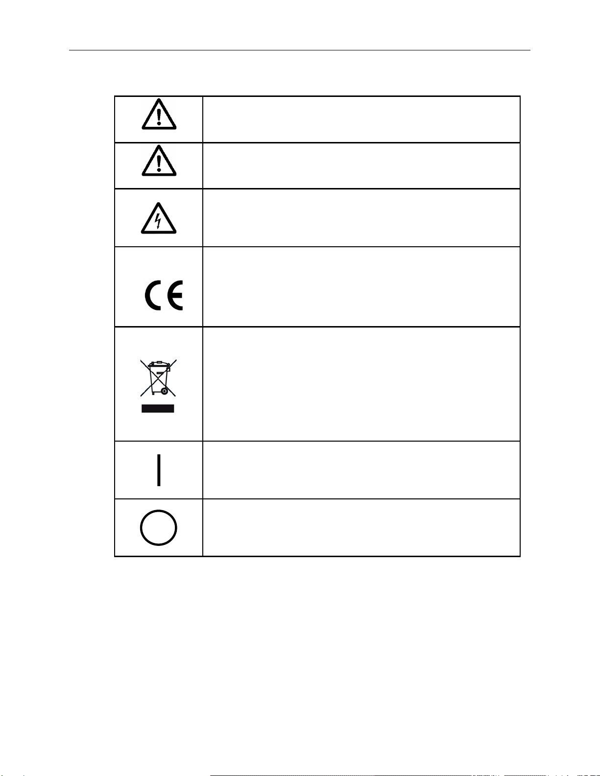
1.1 SYMBOLS AND DEFINITIONS .............................................................................................6
1.2 GENERAL WARNINGS .........................................................................................................7
1.3 ELECTRICAL HAZARDS.......................................................................................................7
1.4 MECHANICAL HANDLING....................................................................................................8
1.5 OPTICS CARE AND HANDLING...........................................................................................8
2INTRODUCTION..................................................................................................................................9
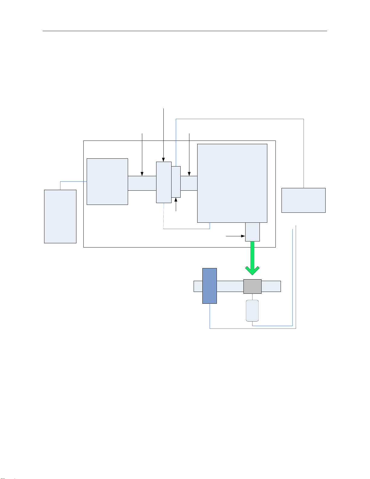
2.1 OPTICAL CONFIGURATION.................................................................................................9
2.2 STRAY LIGHT REJECTION ................................................................................................10
2.3 AVAILABLE MODELS..........................................................................................................10
2.4 TYPICAL APPLICATIONS...................................................................................................11
3INITIAL SETUP ..................................................................................................................................12
3.1 WHAT’S INCLUDED............................................................................................................12
3.2 UNPACKING........................................................................................................................12
3.3 CHOOSING A LOCATION...................................................................................................12
3.4 MOUNTING OPTIONS.........................................................................................................13
3.5 ELECTRICAL AND COMPUTER CONNECTIONS.............................................................14
4SHUTTER...........................................................................................................................................16
4.1 REMOTE OPERATION........................................................................................................16
5INPUT AND OUTPUT SLITS .............................................................................................................17
5.1 FIXED SLITS........................................................................................................................17
5.2 MICROMETER ADJUSTABLE SLITS .................................................................................18
5.3 MOTORIZED SLITS.............................................................................................................20
6DIFFRACTION GRATINGS ...............................................................................................................21
6.1 GRATING TYPES ................................................................................................................22
6.2 GRATING EFFICIENCY AND BLAZING .............................................................................23
6.3 POLARIZATION EFFECTS..................................................................................................26
7MONOCHROMATOR RESOLUTION................................................................................................27
7.1 DETERMINING RESOLUTION............................................................................................28
8GETTING LIGHT INTO A MONOCHROMATOR...............................................................................31
8.1 ACCEPTANCE PYRAMID ...................................................................................................31
8.2 F NUMBER MATCHING ......................................................................................................32
9BLOCKING HIGHER ORDER RADIATION.......................................................................................33
9.1 ORDER SORTING FILTERS...............................................................................................33
10 COMMUNICATION METHODS.........................................................................................................34
10.1 UTILITY SOFTWARE...........................................................................................................35
10.2 HAND CONTROLLER..........................................................................................................36
10.3 TRACQ BASIC SOFTWARE ...............................................................................................37
10.4 LOW-LEVEL COMMANDS ..................................................................................................38
10.5 MONO TERM SOFTWARE AND LABVIEW EXAMPLES...................................................38
11 GRATING INSTALLATION AND CALIBRATION...............................................................................39
11.1 RECALIBRATION SERVICES.............................................................................................39
11.2 SETTING THE WAVELENGTH OFFSET............................................................................39
11.3 DETERMINING THE GRATING CALIBRATION FACTOR .................................................40
11.4 GRATING INSTALLATION ..................................................................................................41
12 TROUBLESHOOTING .......................................................................................................................43
12.1 CORRUPTED MEMORY .....................................................................................................43
12.2 GRATING TURRET POSITION ERROR.............................................................................44
13 SPECIFICATIONS..............................................................................................................................45
14 DIMENSIONS.....................................................................................................................................46
15 EU DECLARATION OF CONFORMITY.............................................................................................48

MCS260
CORNERSTONE 260 MONOCHROMATORS
3
16 APPENDIX I: LOW LEVEL COMMANDS AND QUERIES ................................................................49
16.1 OPENING LOW LEVEL COMMUNICATION INTERFACE .................................................49
16.2 COMMAND AND QUERY SYNTAX ....................................................................................49
16.3 STANDARD MODE..............................................................................................................50
16.4 HANDSHAKE MODE...........................................................................................................51
16.5 COMMAND REFERENCE SUMMARY................................................................................52
16.6 DETAILED COMMAND REFERENCE ................................................................................53
16.7 ERROR CODES FOR LOW LEVEL COMMANDS..............................................................58
17 APPENDIX II: HAND CONTROLLER COMMANDS.........................................................................59
17.1 ACTIVATING THE HAND CONTROLLER...........................................................................59
17.2 USING THE KEYPAD ..........................................................................................................59
17.3 KEY REFERENCE...............................................................................................................60
18 APPENDIX III: USB DLL ...................................................................................................................62
18.1 GENERAL CONSIDERATIONS...........................................................................................62
18.2 LABVIEW USERS................................................................................................................62
18.3 C# USERS ...........................................................................................................................63
18.4 C++ USERS .........................................................................................................................66
19 APPENDIX IV: GRATING PHYSICS TUTORIAL..............................................................................67
19.1 THE GRATING EQUATION.................................................................................................67
19.2 THE GRATING EQUATION IN PRACTICE.........................................................................68
19.3 GRATING ORDER...............................................................................................................69
19.4 GRATING DISPERSION......................................................................................................70
19.5 GRATING ILLUMINATION AND RESOLUTION..................................................................70
20 WARRANTY AND SERVICE .............................................................................................................71
20.1 CONTACTING NEWPORT CORPORATION......................................................................71
20.2 REQUEST FOR ASSISTANCE / SERVICE.........................................................................72
20.3 REPAIR SERVICE...............................................................................................................72
20.4 NON-WARRANTY REPAIR.................................................................................................72
20.5 WARRANTY REPAIR ..........................................................................................................73
20.6 LOANER / DEMO MATERIAL..............................................................................................74

MCS260
CORNERSTONE 260 MONOCHROMATORS
4
LIST OF FIGURES
Figure 1: Optical Configuration of the Cornerstone 260 ..............................................................................9
Figure 2: Model Number Codes.................................................................................................................10
Figure 3: Application Example: Quantum Efficiency Measurements........................................................11
Figure 4: Model 74104 Mounting Kit..........................................................................................................13
Figure 5: Monochromator Connections......................................................................................................15
Figure 6: Remote Shutter Control BNC Connector....................................................................................16
Figure 7: A Fixed Slit Installed into the Holder...........................................................................................17
Figure 8: Available Fixed Slits....................................................................................................................17
Figure 9: A Micrometer Adjustable Slit.......................................................................................................18
Figure 10: A Fully Closed Micrometer Adjustable Slit................................................................................18
Figure 11: Shortest Micrometer Adjustable Slit Height..............................................................................19
Figure 12: Tallest Micrometer Adjustable Slit Height.................................................................................19
Figure 13: A Motorized Slit.........................................................................................................................20
Figure 14: Mono Utility Software Slit Control.............................................................................................20
Figure 15: Gratings Installed onto Mounts.................................................................................................21
Figure 16: Grating Properties Table...........................................................................................................22
Figure 17: Grating Efficiency Curves, High Resolution and Extended Range Models..............................24
Figure 18: Grating Efficiency Curves, UV-VIS and VIS-NIR Models.........................................................25
Figure 19: Resolution vs. Throughput........................................................................................................27
Figure 20: Some of the Fixed Slit Sizes Available.....................................................................................30
Figure 21: Acceptance Pyramid of Monochromator ..................................................................................31
Figure 22: Grating Correctly “Filled” with Light ..........................................................................................31
Figure 23: Mismatched F Numbers Resulting in Stray Light .....................................................................32
Figure 24: F Number Matcher Used with Fiber Optic Cable......................................................................32
Figure 25: Model 74010 Filter Wheel.........................................................................................................34
Figure 26: Mono Utility Software Screens..................................................................................................35
Figure 27: Cornerstone 260 Monochromator with 74009 Hand Controller................................................36
Figure 28: TracQ Basic Screens................................................................................................................37
Figure 29: Query Using MonoTerm Software............................................................................................38
Figure 30: Grating Platform Without Gratings............................................................................................42
Figure 31: Grating Platform With Three Gratings Installed........................................................................42
Figure 32: Entering Calibration Values in Utility Software.........................................................................43
Figure 33: Grating Turret Position Sensor Pin Range ...............................................................................44
Figure 34: Cornerstone 260 Dimensions...................................................................................................46
Figure 35: Micrometer Adjustable Slit Dimensions....................................................................................47
Figure 36: Model 74104 Mounting Kit........................................................................................................47
Figure 37: 74009 Hand Controller Keypad ................................................................................................59
Figure 38: MonoTerm LabVIEW Source Code..........................................................................................62
Figure 39: The Sawtooth Pattern of a Grating Section..............................................................................67
Figure 40: The Grating Equation Satisfied for a Parallel Beam of Monochromatic Light ..........................68
Figure 41: Polychromatic Light Diffracted From a Grating.........................................................................68
Figure 42: Sign Convention for the Angle of Incidence, Angle of Diffraction and Grating Angle...............69

MCS260
CORNERSTONE 260 MONOCHROMATORS
5
1 GENERAL INFORMATION
Thank you for your purchase of this Cornerstone™260 Monochromator from Oriel Instruments®.
Please carefully read the following important safety precautions prior to unpacking and operating this
equipment. In addition, please refer to the complete User’s Manual and all other documentation provided
for additional important notes and cautionary statements regarding the use and operation of the system.
Do not attempt to operate any system without reading all the information provided with each of the
components.
Please read all instructions that were provided prior to operation of the system. If
there are any questions, please contact Oriel Instruments or the representative
through whom the system was purchased.

MCS260
CORNERSTONE 260 MONOCHROMATORS
6
1.1 SYMBOLS AND DEFINITIONS
WARNING
Situation has the potential to cause bodily harm or death.
CAUTION
Situation has the potential to cause damage to property or equipment.
ELECTRICAL SHOCK
Hazard arising from dangerous voltage. Any mishandling could result
in irreparable damage to the equipment, and personal injury or death.
EUROPEAN UNION CE MARK
The presence of the CE Mark on Newport Corporation equipment
means that it has been designed, tested and certified as complying
with all applicable European Union (CE) regulations and
recommendations.
WEEE
This symbol on the product or on its packaging indicates
that this
product must not be disposed of with regular waste. Instead, it is the
user’s responsibility to dispose of waste equipment according to the
local laws. The separate collection and recycling of the waste
equipment at the time of disposal will he
lp to conserve natural
resources and ensure that the materials are recycled in a manner that
protects human health and the environment.
ON
The ON symbol in the above figure indicates the ON position of the
power switch.
OFF
The OFF symbol in the above figure indicates the OFF position of the
power switch.

MCS260
CORNERSTONE 260 MONOCHROMATORS
7
1.2 GENERAL WARNINGS
•Read all warnings and operating instructions for this system prior to setup and use.
•Do not use this equipment in or near water.
•To prevent damage to the equipment, read the instructions in the equipment manual for proper
input voltage and check the requirement on the power supply.
•This equipment is grounded through the grounding conductor of the power cord.
•Route power cords and other cables so they are not likely to be damaged.
•Disconnect power before cleaning the equipment
•Do not use liquid or aerosol cleaners; use only a damp lint-free cloth.
•Lock out all electrical power sources before servicing the equipment.
•To avoid explosion, do not operate this equipment in an explosive atmosphere.
•Qualified service personnel should perform safety checks after any service.
•If this equipment is used in a manner not specified in this manual, the protection provided by this
equipment may be impaired.
•Do not position this product in such a manner that would make it difficult to disconnect the power
cords.
•Use only the specified replacement parts.
•Follow precautions for static sensitive devices when handling this equipment.
•This product should only be powered as described in the manual.
•Do not remove the cover for normal usage.
1.3 ELECTRICAL HAZARDS
Make all connections to or from the instrument with the power off.
The Cornerstone requires DC voltage for operation, which is provided by an external power
supply.This power supply has no user serviceable parts. Do not attempt to open the external
power supply. Do not attempt to work in the Cornerstone compartment without first disconnecting
the power cord, since electrical hazards are present inside the compartment even with the power
switch in the “off” position.
The Cornerstone monochromator contains a microprocessor and should be installed with
appropriate surge/EMI/RFI protection on the power line. A dedicated power line or line isolation
may be required for some extremely noisy sites. The electronic circuits within the monochromator
are extremely sensitive to static electricity and radiated electromagnetic fields. Operation of this
instrument close to intense pulsed sources (lasers, xenon strobes, arc lamps, etc.) may
compromise performance if shielding is inadequate, and may cause permanent damage to the
microprocessor.
Note: This instrument conforms to CE standards for both safety and EMC. During normal use, this
equipment will not pose any electrical hazards to the user. Read all warnings before installing or
operating this system. If there are any questions or concerns, contact Oriel Instruments or the
regional sales representative for Newport.

MCS260
CORNERSTONE 260 MONOCHROMATORS
8
1.4 MECHANICAL HANDLING
Avoid dropping, sudden shocks, or rough handling of the monochromator since this may cause the
system to lose its calibration and may destroy the high precision drive components or optics.
1.5 OPTICS CARE AND HANDLING
Do not touch any optical surfaces since this is likely to cause irreparable damage. Always wear
powder-free gloves to cover the entire hand, not finger cots. Never touch the surface of a
diffraction grating, even when wearing gloves.
Dust or debris on the grating surface may negatively impact performance, so it should be
prevented from entering the instrument by keeping the protective grating covers in place when it is
not in use. If the gratings do require cleaning, do not attempt to clean any optical surface except
by blowing off dust or lint particles with a stream of dry clean air or nitrogen. Wiping the grating
surface will cause permanent damage.
Avoid getting any moisture or condensation onto the grating. Do not breathe on or talk directly in
front of a grating, as the moisture from one’s breath should never be allowed to condense on the
grating surface.
This instrument comes with gratings pre-installed, aligned and the calibration parameters set. An
experienced user may choose to install a different grating in the field, although it is strongly
encouraged to send the instrument back to the factory instead.
If a grating is installed in the field, the grating cover must never touch the grating’s front surface.
The specially designed grating cover contacts only the edges of the grating. When removing this
cover, a grating can be scratched easily, so use extreme caution when handling.
Hand tighten the grating mount screws. Do not use tools, since this may cause damage to the
drive assembly. Never touch the surface of the grating, even while wearing gloves. Handle the
grating assembly only by its mount.

MCS260
CORNERSTONE 260 MONOCHROMATORS
9
2 INTRODUCTION
The Oriel Cornerstone 260 is a high performance, economical and user-friendly monochromator – an
ideal instrument for research and OEM applications.
Each of these instruments includes up to three diffraction gratings, filter wheel control circuitry and an
integrated electronic shutter. Communication may be established using USB, RS232, GPIB (IEEE-488)
or an optional hand controller designed specifically for use with the Cornerstone family of
monochromators.
The Cornerstone 260 includes a utility program designed to run on a computer using the Microsoft
Windows operating system. The simple, intuitive interface means that users can get up and running
within minutes of opening the box. Instrument control examples using National Instruments LabVIEW are
provided, along with a command set and API for those wishing to develop their own programs. An
optional hand controller may be used for quick access to all common commands and queries, without
requiring a computer. This is especially beneficial in universities and secure facilities.
A wide selection of preconfigured grating selections are available for the Cornerstone 260, as well as
special order options. Throughput and resolution can be adjusted by selecting the appropriate slit size.
Fixed slits are available for high accuracy and repeatability, and micrometer adjustable slits may be used
for maximum flexibility. Automatic bandpass control is available with the use of motorized slits.
2.1 OPTICAL CONFIGURATION
The optical design of the Cornerstone 260 is based upon an asymmetrical in-plane version of a
Czerny-Turner monochromator. The optical configuration is designed to ensure high resolution
and maximum throughput. This F/3.9 monochromator is optimized to provide excellent stray light
rejection while minimizing aberrations. A high precision motor is used to select the desired
wavelength and switch between diffraction gratings quickly, without sacrificing performance.
Figure 1: Optical Configuration of the Cornerstone 260

MCS260
CORNERSTONE 260 MONOCHROMATORS
10
2.2 STRAY LIGHT REJECTION
Stray light may have a variety of origins. Its presence may be caused by a wide variety of design
and manufacturing factors. The level of stray light due to the dispersed radiation inside the
monochromator is affected by the design of the instrument, its baffles and interior finish. The
Cornerstone 260 incorporates a sophisticated design, proven materials, and a quality
manufacturing system to ensure high stray light rejection.
The amount of stray light measured on top of true signal will depend on many experimental factors
as well as the performance of the instrument. When comparing stray light specifications, it is
important to compare values that were measured under identical circumstances. The spectral
distribution of the source and the response of the detection system are often the dominant factors
when determining a stray light value.
2.3 AVAILABLE MODELS
The model number of each Cornerstone monochromator reflects its features. Refer to the part
number code to determine the features present in the instrument. If the model number differs from
the code, it is a Special Order configuration. In that case, refer to the Sales Order for the
instrument for more information.
CS260- _ _ _ - _ - _ _ - _
COMPUTER INTERFACE
RG = RS232 and GPIB (IEEE-488)
USB = USB 2.0
GRATING CONFIGURATION
1 = High Resolution
2 = UV-VIS
3 = Extended Range
4 = Near Infrared
Q = High Resolution Extended Range
INPUT AND OUTPUT SLITS
FH = Fixed Slit Holders
MC = Micrometer Adjustable Slits
MT = Motorized Slits
OUTPUT PORT
A = Axial Output Port
D = Dual Output Ports (Axial and Lateral)
Figure 2: Model Number Codes

MCS260
CORNERSTONE 260 MONOCHROMATORS
11
2.4 TYPICAL APPLICATIONS
The applications for the Cornerstone 260 monochromator are practically limitless. Here we
present one example: a quantum efficiency measurement system using an optically chopped light
source used with a lock-in digital amplifier to extract small signal levels from background radiation.
All components shown are available from Oriel Instruments.
300W Xenon
Light Source Cornerstone™ 260
1/4m Monochromator
Motorized Filter Wheel
Optical
Chopper
Collimating and
Focusing Optics Light shield
Focusing Lens
Assembly
Tunable monochromatic light source
on mounting plate
LIDA-SRS-KIT
Lock-In Digital
Amplifier
Arc Lamp
Power Supply
Solar
Cell
Calibrated
Reference
Detector
Optical Rail
Preamplifier
Figure 3: Application Example: Quantum Efficiency Measurements

MCS260
CORNERSTONE 260 MONOCHROMATORS
12
3 INITIAL SETUP
3.1 WHAT’S INCLUDED
•Preselected diffraction gratings, installed and aligned
•Electronic shutter at input port
•A choice of single or dual output ports
•A choice of micrometer adjustable slits, motorized or fixed slit holders at the input port and
output port(s)
•A choice of electronics interface for GPIB/RS232 or USB communication
•LabVIEW™ based utility software
•Application Programming Interface (API) for LabVIEW with examples
•MonoTerm low-level command software
•Certificate of Calibration
•Monochromator Power Supply
•Line cords (U.S. and Europe)
•User’s manual
3.2 UNPACKING
Remove all items from the shipping containers and verify each item is accounted for. The
instrument is carefully packaged to minimize the possibility of damage during shipment. Inspect
the shipping box for external signs of damage or mishandling. Inspect the contents for damage.
If any item is missing or damaged, immediately contact Oriel Instruments or the Newport
representative from whom the system was purchased.
It is suggested to save the packaging material and shipping container, in case the equipment
needs to be relocated at a future date.
WARNING
Do not attempt to operate this equipment if there is evidence of
shipping damage or there is suspicion that the equipment will not
operate correctly. Damaged equipment may present hazards.
3.3 CHOOSING A LOCATION
Choose an installation location where the power requirements can be met for the monochromator,
as well as the rest of the optical system. Be sure power is not applied to the system until the setup
has been completed and all electrical connections made.
Ensure that there is easy access to the monochromator’s power switch and the electrical outlet.

MCS260
CORNERSTONE 260 MONOCHROMATORS
13
3.4 MOUNTING OPTIONS
The ability to mount the monochromator simplifies setup and alignment of the optical system. The
mounting plate or kits also helps ensure consistent results over time, as the monochromator
cannot be accidentally moved out of position. The following options are available for securing the
Cornerstone 260:
•Mounting plate
•Mounting kit to couple with Oriel’s Research Lamp Housings
•Optical rods
The 74105 Mounting Plate is used to secure a Cornerstone 260 Monochromator to an inch or
metric optical table. The plate adds 0.25 inch [6.35 mm] to the optical height. If the Cornerstone
260 will be used with Oriel’s research lamp housing, consider using the 74104 mounting kit.
The 74104 Mounting Kit connects the Cornerstone 260 monochromator to an arc lamp or quartz
tungsten halogen light source. This kit is compatible with Oriel's Research Lamp Housings that
hold 50 to 250 watt lamps. It includes a base plate, a flexible light shield, a 1.5-inch diameter
focusing lens and lens holder. All the hardware required to mount the lamp housing and
monochromator to the base plate is provided. The mounting kit's base plate uses four adjustable
leveling feet. The feet may be removed to secure the base plate to an inch or metric optical table.
The most economical option is to use optical rods and rod holders to mount the Cornerstone 260
to an optical table or breadboard. On the monochromator’s mounting surface, four #1/4-20
threaded holes may be used to install standard optical rods. Care should be taken to ensure the
instrument is level and secured well enough that its location remains consistent over time, even if
the instrument is bumped or components coupled to the ports.
Figure 4: Model 74104 Mounting Kit

MCS260
CORNERSTONE 260 MONOCHROMATORS
14
3.5 ELECTRICAL AND COMPUTER CONNECTIONS
Before powering up the system for the first time, it is suggested to have a qualified electrician
verify the wall socket to be used with the instrument meets the requirements for operation as
noted.
Before making any electrical connections, verify the front panel power switch is in the off position
for the monochromator.
WARNING
To avoid electric shock, connect the instrument to properly earth-
grounded, 3-
prong receptacles only. Failure to observe this
precaution can result in severe injury or death.
The line voltage requirement is as follows:
Monochromator Power Adapter 100 to 240 VAC, 47-63 Hz
The monochromator conforms to CE standards for both safety and EMC. During normal use, this
equipment will not pose any electrical hazards to the user. Read all warnings before installing or
operating this system. If there are any questions or concerns, contact Oriel Instruments or the
regional sales representative for Newport.
ELECTRICAL SHOCK
Never attempt to open the lamp power supply or monochromator
power adapter. These items do not contain any user serviceable
parts. Failure to follow this warning can result in severe injury or
death.
The monochromator’s power adapter connects to an AC wall socket and supplies DC voltage to
the instrument. Do not open the monochromator cover and attempt to work inside without first
turning the instrument off and disconnecting the power cord from the AC mains.
The ribbon cable connecting the monochromator to the optional model 74010 filter wheel is
installed before the system ships out. The monochromator provides power to the filter wheel and
allows the user to select which filter is placed in the optical path.
Ensure the monochromator power switch is in the off position (marked as O). Then connect the
power adapter to the monochromator, as shown.Insert the power cord provided into the power
adapter and connect to the AC mains.
Connect the USB, RS232 or GPIB cable to the monochromator. Plug the other end of the USB
cable into the computer only after the TracQ Basic software is installed.

MCS260
CORNERSTONE 260 MONOCHROMATORS
15
Figure 5: Monochromator Connections
The USB models of the Cornerstone 260 each include a USB 2.0 cable. A GPIB cable (model
70038) and RS232 cable (model 70040) are available from Oriel, and are sold separately.
If using a commercially available USB/GPIB or USB/RS232 converter cable, the driver for this cable
must be installed before communication to the monochromator can be established.
Follow the instructions provided in the Quick Start Guide to install the utility software onto a
computer.

MCS260
CORNERSTONE 260 MONOCHROMATORS
16
4 SHUTTER
An electronic shutter is integrated into the Cornerstone monochromator’s design. It is mounted inside the
housing at the input port. This shutter is normally closed.
The shutter is used to close the light path when light is not required. This allows the light source to
remain on, and therefore remain warmed up, so that it continues to provide stable performance.
Additionally, restarting a lamp results in wear of the filament (with quartz tungsten halogen lamps) or wear
of the anode/cathode (with arc lamps). Therefore, when the light is not needed during short periods,
closing the shutter is suggested.
Diffraction gratings are mounted on a rotating turret inside the monochromator. When the
monochromator switches between diffraction gratings, the changing angle of the grating causes light to
be diffracted at various wavelengths. This includes white light, which is output at a higher power than
other individual wavelengths. In order to prevent saturation of a detection system, it is suggested to close
the shutter temporarily while changing gratings. It is especially important to prevent saturation and
possible damage when using a photomultiplier tube.
A scan may be completed while the shutter is closed to perform background subtraction calculations on
subsequently scans completed while the shutter is open.
Please note that the shutter is not designed to block high power direct light. When using a 450W or
greater light source, heat mitigation strategies should be employed. For example, Oriel offers liquid filters
to protect the shutter, filters and other items from potential heat damage.
4.1 REMOTE OPERATION
The BNC female connector located on the outside of the monochromator allows the shutter to be
controlled remotely, if desired. A TTL low condition will open the shutter. The shutter may also be
opened by completing a connection between the BNC conductor and shield (i.e. shorting out the
connector). Control can be overridden by the shutter commands issued from a computer or the
optional hand controller.
Figure 6: Remote Shutter Control BNC Connector

MCS260
CORNERSTONE 260 MONOCHROMATORS
17
5 INPUT AND OUTPUT SLITS
To operate any monochromator, slits are required at the input and output port. The slits offered with the
Cornerstone 260 all have 1.5-inch male flanges, allowing them to be easily connected to the wide variety
of Oriel accessories and instruments.
Note: The slits need to be the same width and height at the input and output ports. A wider input slit
when compared to the output slit results in more stray light inside the instrument. A wider output slit with
respect to the input slit will not increase throughput.
5.1 FIXED SLITS
The fixed slits slide into the holders at the input and output port. The width and height cannot be
adjusted, but may be individually replaced with other slit sizes. Fixed slits are a low cost alternative
to micrometer adjustable or motorized slits, and provide excellent repeatability. They are a good
choice when only a few slit sizes are required.
Fixed slits are sold separately to allow customized choices based on the needs of the application.
When ordering, be sure to purchase two fixed slits of the same model for single output port
instruments – one for the input port, and the other for the output port. When ordering, be sure to
purchase three fixed slits of the same model for dual output port instruments – one for the input
port, and the others for the output ports. Insert the slit as shown, with the label facing outward. Be
sure that it is fully inserted into the holder’s slot to ensure the best performance and repeatability.
Figure 7: A Fixed Slit Installed into the Holder
Fixed Slit Model
Width
Height
77222
10 µm
2 mm
77220
25 µm
3 mm
77219
50 µm
6 mm
77218
120 µm
18 mm*
77217
280 µm
18 mm*
77216
600 µm
18 mm*
77215
760 µm
18 mm*
77214
1.24 mm
18 mm*
77213
1.56 mm
18 mm*
77212
3.16 mm
18 mm*
*Actual slit height is 18 mm, usable height is 12 mm.
Figure 8: Available Fixed Slits

MCS260
CORNERSTONE 260 MONOCHROMATORS
18
5.2 MICROMETER ADJUSTABLE SLITS
Micrometer adjustable slit assemblies are continuously variable from fully closed to 3 mm width. A
height adjustment slide allows variation in the height from 2 to 12 mm. Benefits of the micrometer
adjustable slits are flexibility and high throughput. This type of slit is designed primarily for
versatility and convenience in changing resolution and throughput, which are related to the slit
width.
Figure 9: A Micrometer Adjustable Slit
The slit width setting is read on the micrometer. A set of numbers go around the turning dial.
Another set of numbers are located on the shaft. When the zeroes in both these locations line up,
the slit is fully closed. Turning the dial clockwise advances the dial position further down on the
shaft, closer to the body of the micrometer. This opens the slit.
Use a 10x multiplier to convert the micrometer reading to the actual slit opening size. For
example, turning the dial one full revolution starting from the fully closed position will give a
reading of 50 on the micrometer. Using the multiplier, this indicates the micrometer width is set to
500 um. If unsure of the reading, begin at the fully closed position and add up each full revolution
made.
Figure 10: A Fully Closed Micrometer Adjustable Slit
The micrometer is used to make the slit
narrow or wide
The slide is used to
change the slit height

MCS260
CORNERSTONE 260 MONOCHROMATORS
19
The slit height is continuously adjustable. Pull the lever out for the shortest height. Push the slide
in for the tallest height setting.
Use a 10x multiplier to convert the micrometer reading to the actual slit opening size. For
example, turning the dial one full revolution starting from the fully closed position will give a
reading of 50 on the micrometer. Using the multiplier, this indicates the micrometer width is set to
500 um. If unsure of the reading, begin at the fully closed position and add up each full revolution
made.
Figure 11: Shortest Micrometer Adjustable Slit Height
Figure 12: Tallest Micrometer Adjustable Slit Height
This manual suits for next models
43
Table of contents
Other Newport Industrial Equipment manuals

Newport
Newport FMS Series User manual

Newport
Newport New Focus 8892 User manual

Newport
Newport UTM Series User manual

Newport
Newport RV User manual

Newport
Newport PM 500 Installation manual

Newport
Newport GTS-V Series User manual

Newport
Newport IDL165-LM Series User manual

Newport
Newport TSP Series User manual

Newport
Newport GTS30V User manual
Popular Industrial Equipment manuals by other brands

ABB
ABB PowerCube PB/F Installation and service instructions

Endress+Hauser
Endress+Hauser Flexdip CYA112 operating instructions

Radicon
Radicon J Series manual

MSW
MSW WIRESTRIPPER-002-1500 user manual

stellar labs
stellar labs TireMan 12154 owner's manual

Mayr
Mayr EAS-HT 405 Series Installation and operational instructions