riverhawk IM-278 User manual
Repairs – Rentals
Field Service
215ClintonRoad
NewHartford,NY13413
Tel:+13157684855
Fax:+13157684941
Email:[email protected]
RevisionA
Page1of32
INSTRUCTIONMANUALIM‐278
ForHydraulicallyTensionedStudsandNuts
ApplicableBoltingConnections
9EGasTurbinetoLoadCoupling
LoadCouplingtoSubstituteShaft
SubstituteShafttoLoadCoupling
LoadCouplingto9A5Generator
ApplicableGEOrderingSheetPartNumbers
102T3330P001
102T3330P002
102T3330P003
102T3330P004
102T3330P005
102T3330P006
102T3330P007
104T5015P001
104T5015P002
104T5015P003
104T5015P004
104T5015P005
104T5015P006
104T5015P007
GEPower&Water
GENERALELECTRICCOMPANY
MLI: ____ OF ____
DATE
CUSTOMER'SINFORMATIONBOX
CONTENTSAREINDEPENDENTOFRIVERHAWKDOCUMENTCONTROL
ISSUED:
THISDOCUMENTSHALLBEREVISEDINITSENTIRETY.ALLSHEETSOFTHISDOCUMENTARE
THESAMEREVISIONLEVELASINDICATEDINTHISVENDORSUPPLIEDDRAWINGAPPLIQUE.
REV
373A4054
GEDRAWINGNUMBER
VENDORSUPPLIED
THISDOCUMENTISFILEDUNDERTHEGEDRAWINGNUMBER.
GENOTTOREVISE.GEREVISIONLEVELISSHOWNONTHISAPPLIQUE.
GESIGNATURES
CHECKED:
TheRiverhawkCompanyreservestherighttomakechangesupdatingthisdocumentwithoutdissemination
ornotice.Thelatestrevisionlevelmaybeobtainedbycontacting Riverhawk Company directly or at our
websitewww.riverhawk.com.

Instruction Manual IM-278
CUSTOMER'SINFORMATIONBOX
CONTENTSAREINDEPENDENTOFRIVERHAWKDOCUMENTCONTROL
215ClintonRoad
NewHartford,NY13413
Tel:+13157684855
Fax:+13157684941
Email:[email protected]
REV
373A4054
GEDRAWINGNUMBER
RevisionA
Page2of32
TableofContents
Section Description PageNumber
1.0 CautionsandSafetyWarnings 3
2.0 ScopeandGEPartNumberCross‐Reference 4
3.0 QuickCheck‐List 5
4.0 GeneralPreparations 9
5.0 HardwareSetPreparations 11
6.0 NutandStudAssembly 14
7.0 AssemblyofTensioneronStud 17
8.0 StudPullingandTensioning 19
9.0 ThreadLocking 22
10.0 Stud/NutRemoval 23
11.0 Storage 24
12.0 FrequentlyAskedQuestions 24
13.0 RevisionHistory 26
AppendixA1 ECDeclarationofConformity 27
AppendixA2 UKCADeclarationofConformity 28
AppendixB1 16‐BoltTensioningPatternRecordSheet 29
AppendixB2 14‐BoltTensioningPatternRecordSheet 30
AppendixB3 14‐BoltTensioningPatternRecordSheet 31
AppendixB4 14‐BoltTensioningPatternRecordSheet 32

Instruction Manual IM-278
CUSTOMER'SINFORMATIONBOX
CONTENTSAREINDEPENDENTOFRIVERHAWKDOCUMENTCONTROL
215ClintonRoad
NewHartford,NY13413
Tel:+13157684855
Fax:+13157684941
Email:[email protected]
REV
373A4054
GEDRAWINGNUMBER
RevisionA
Page3of32
1.0CautionsandSafetyWarnings
NOTICE
Asofsummer2011,thismanualistobeusedinrelationtotheinterlockingstyletensioner.This
new tensioner can be identified buy its ORANGE safety guard. Note: yellow guarded tensioner
requirestheuseofdifferentsetofinstructions,consultRiverhawkforassistance
TOAVOIDFAILURE,ENSURESAFETYANDPROPEROPERATIONTHETENSIONERANDINTERLOCK
SAFETYGUARDMUSTINSTALLEDONTHEFLANGEBEFORETENSIONINGBEGINS.DONOTUSETHE
TENSIONERASSEMBLYATANYPRESSUREUNLESSTHETOOLISINSTALLEDONTHEFLANGE.
WARNING
Impropertooluseandthefailuretofollowthecorrectproceduresaretheprimaryrootcausesoftool
failuresandpersonalinjuries.Alackoftrainingorexperiencecanleadtoincorrecthardware
installationorincorrecttooluse.Onlytrainedoperatorswithcareful,deliberateactionsshoulduse
hydraulictensioners.ContactRiverhawkCompanywithanytrainingneeds.
WARNING
Riskofhighpressurefluidinjection.Riverhawktoolsoperateunderhighpressure.Thoroughlyinspect
allhosesandconnectionsfordamageorleakspriortousingthisequipment.
CAUTION
Personalinjuryandequipmentdamagecanoccurifthepullerscrewisnotsecurelyengagedwith
thecleanconicalthreadofthestud.Properengagementisachievedwhenthepullerscrewistight
inthestudandisnotcross‐threadedintotheconicalthread.(ReferenceIM‐220)
WARNING
Theproperpersonalprotectiveequipmentmustbewornatalltimes.Riverhawkrecommendsata
minimum,safetyglasses,longsleeveshirt,hardhat,heavyworkgloves,andsteeltoeshoes.
WARNING
ThesafetyguardMUSTbeinplaceandhandskeptoutofdesignatedareasatalltimeswhenthe
tensionerispressurizedotherwisepersonalinjurycanoccur.
CAUTION
DONOTEXCEEDTHEMAXIMUMPRESSUREMARKEDONTHETENSIONER.Excessivepressurecan
damagethestudandthepullerscrew.

Instruction Manual IM-278
CUSTOMER'SINFORMATIONBOX
CONTENTSAREINDEPENDENTOFRIVERHAWKDOCUMENTCONTROL
215ClintonRoad
NewHartford,NY13413
Tel:+13157684855
Fax:+13157684941
Email:[email protected]
REV
373A4054
GEDRAWINGNUMBER
RevisionA
Page4of32
WARNING:
Keephandsclearofthetoolwhilethepressureisbuildingup.Thisincludesthepinwrenchfor
tighteningthespannerring(nut).Oncethetoolisstabilizedatpressurethenandonlythencanthe
nutbetightened.Thisreducesthepotentialofpersonalinjury.
Note:Beforethreadingthepullerscrewintothestud,carefullycheckthecleanlinessofboththe
stud's and the puller screw's conical threads. Apply a light coat of clean turbine oil or a spray
lubricanttothepullerscrew.Donotuse“NeverSeize”ontheconicalthreads.Thisprocedurewill
easeassemblyandassurepositivematingofthethreadsbeforetightening.
2.0Scope
Thisdocumentdescribesthestepstoinstallasetofhardwarecontainingthestudsandnuts
suppliedbyRiverhawkCompanyattheturbine/coupling;coupling/substituteshaft;substitute
shaft/couplingandcoupling/generatorconnections.Thishardwareisdepictedonthefollowing
drawings.Thesedrawingsaswellastoolingdrawingsformpartofthismanual.
Riverhawk
HardwareSetPart
Number
GEDrawing
Numberfor
HardwareSet
GEOrderingSheet
PartNumber
HardwareSet
Description
HF‐5369 269B8701
102T3330P001
102T3330P002#
104T5015P001
104T5015P002#
2‐3/4"hardwareforAll4bolted
joints.
- - 102T3330P003#
104T5015P003#
Hydraulicinstallationtoolingonly
HF‐5578 269B8737 102T3330P004
104T5015P004
2‐3/4"hardwarefortheturbine
endtoloadcouplingconnection.
HF‐5579 269B8738 102T3330P005
104T5015P005
2‐3/4"loadcouplingto
substituteshaftconnection.
HF‐5580 269B8739 102T3330P006
104T5015P006
2‐3/4"substituteshafttoload
couplingconnection.

Instruction Manual IM-278
CUSTOMER'SINFORMATIONBOX
CONTENTSAREINDEPENDENTOFRIVERHAWKDOCUMENTCONTROL
215ClintonRoad
NewHartford,NY13413
Tel:+13157684855
Fax:+13157684941
Email:[email protected]
REV
373A4054
GEDRAWINGNUMBER
RevisionA
Page5of32
HF‐5581 269B8740 102T3330P007
104T5015P007
2‐3/4"loadcoupling9A5
generatorconnection.
#denotesGEpartnumbersthatincludehydraulictooling
OtherImportantReferenceDocumentation:
IM‐293(GE373A4058) InstructionManualforGEHydraulicPumpKit
IM‐220(GE373A4025) CleaningProcedureoftheConicalThreadsonRiverhawkStuds
3.0QuickChecklist
ThefollowingchecklistisintendedasasummaryofthestepsneededtousetheRiverhawk‐supplied
equipment. New personnel or those experienced personnel who have not used the Riverhawk
equipmentrecentlyareencouragedtoreadtheentiremanual.
EQUIPMENTINSPECTION
□ Checkhydraulichoseforanydamage.
□ Testpump,seepumpinstructionmanualIM‐293forprocedure.
□ Inspecttensionerforanydamage.
NUTANDSTUDPREPARATION
□ Inspectstudsandnutsforanydamage.
□ Cleanthestudsandnuts(ReferenceIM‐220).
□ Measurestudlengthsandrecordonstretchdatasheets.
(VERYIMPORTANT)
□ Installstudsandnutsintotheflange.
□ Setstick‐outdimensionontheconicalthreadendofstud.

Instruction Manual IM-278
CUSTOMER'SINFORMATIONBOX
CONTENTSAREINDEPENDENTOFRIVERHAWKDOCUMENTCONTROL
215ClintonRoad
NewHartford,NY13413
Tel:+13157684855
Fax:+13157684941
Email:[email protected]
REV
373A4054
GEDRAWINGNUMBER
RevisionA
Page6of32
□ Handtightennutsonbacksideofstud.
□ Verifystick‐outmeasurement(VERYIMPORTANT)
Tensioning(Studinstallation)
□ Checktensioner’sdrawingforcorrectpartsandpartnumbers.
□ Applyalightcoatofcleanturbineoilorspraylubricanttothepullerscrew.DONOTUSE
“NEVERSEIZE”ONTHECONICALTHREADS.
□ Installspannerringontonut.
□ Threadpullerscrewontothestud.
□ InsertAllenwrenchintothebacksideofthestudtostopthestudfromrotatingwhen
installingpullerscrew.
□ UsinganAllenwrench,tightenthepullerscrew.Thenbackoffpullerscrew1/2aturn.
□ Retightenpullerscrewbyhanduntilitisfullyinserted.DONOTBACKOFFPULLERSCREW.
□ Slidefootoverpullerstudandorientateintoposition.
□ Threadthetensionerontopullerscrew.Lightlyturnthetensionerontothepullerscrew,
untilitstops.Thegapbetweenthefootandtensionerisabout1/16”to3/16”.
□ Placeguardovertensionerandpositionguidepinintotheholeinthebacksideofthestud.
□ Tightenknurledinterlockfittingbyhanduntilitpressesfirmlyagainsttensioner.(nogap)
□ Slideandengagecustomconnectorfromrearofguardtolocktensionerintoplace.
□ Tensionto50%.Consultmanualforcorrectpressure.

Instruction Manual IM-278
CUSTOMER'SINFORMATIONBOX
CONTENTSAREINDEPENDENTOFRIVERHAWKDOCUMENTCONTROL
215ClintonRoad
NewHartford,NY13413
Tel:+13157684855
Fax:+13157684941
Email:[email protected]
REV
373A4054
GEDRAWINGNUMBER
RevisionA
Page7of32
□ Usethepinwrenchinspannerringtotightennut.
□ Releasepressure,allowtensionertofullyretract.
□ Disconnecthosefromtensioner.
□ Loosenknurledfittingandremoveguard.
□ Unscrewtensionerfrompullerscrew.Usecautiontoinsurethathandsarenotbetween
tensionerandcouplingwhentensionerbecomesdisengagedfrompullerscrew.
□ Removefoot.
□ Removepullerscrewfromstud.
□ Removespannerringfromnut,movetonextstudinpattern.
□ Tensionallstudsto50%beforeproceedingtofinalpressure.
□ Repeatabovestepsatfinalpressure.
□ Measurefinalstudlengthandrecordonstretchdatasheets.Calculatestretchandverify
persection8.2
□ Torquenuts’setscrewspersection10.

Instruction Manual IM-278
CUSTOMER'SINFORMATIONBOX
CONTENTSAREINDEPENDENTOFRIVERHAWKDOCUMENTCONTROL
215ClintonRoad
NewHartford,NY13413
Tel:+13157684855
Fax:+13157684941
Email:[email protected]
REV
373A4054
GEDRAWINGNUMBER
RevisionA
Page8of32
Detensioning(Studremoval)
□ Loosennuts'setscrews
□
Inspectandcleanstuds'conicalthreads.DonotcontinueuntilALLdebrisisremoved
fromthethreads!ReferenceinstructionmanualIM‐220.Donottrytousethetensioner
toremoveadamagedstud!
□ Applyalightcoatofcleanturbineoilorspraylubricanttothepullerscrew.DONOTUSE
“NEVERSEIZE”ONTHECONICALTHREADS.
□ Installspannerringontonut.
□ Threadpullerscrewontothestud.
□ UsingAllenwrenchtightenthepullerscrew.Thenbackoffpullerscrew1/2aturn.
□ Lightlyretightenpullerscrewbyhanduntilitisfullyinserted.DONOTBACKOFFPULLER
SCREW.
□ Slidefootoverpullerstudandorientateintoposition.
□ Threadthetensionerontopullerscrew.Lightlyturnthetensionerontothepullerscrew
untilitstops.Thegapbetweenthefootandtensionerisabout1/16”to3/16”.
□ Placeguardovertensionerandpositionguidepinintotheholeinbacksideofstud.
□
Tightenknurledinterlockfittingbyhanduntilitfirmlypressesagainsttensioner.(no
gap)
□ Slideandengagecustomconnectorfromrearofguardtolocktensionerintoplace.
□ Applyfinalpressure.
□ Loosennutwiththespannerringandpinwrench.

Instruction Manual IM-278
CUSTOMER'SINFORMATIONBOX
CONTENTSAREINDEPENDENTOFRIVERHAWKDOCUMENTCONTROL
215ClintonRoad
NewHartford,NY13413
Tel:+13157684855
Fax:+13157684941
Email:[email protected]
REV
373A4054
GEDRAWINGNUMBER
RevisionA
Page9of32
4.0GeneralPreparations
Readandunderstandallinstructionsbeforeinstallingandtensioningstuds
Thisequipmentproducesveryhighhydraulicpressuresandveryhighforces.Operatorsmust
exercisecaution,andproperpersonalsafetyequipmentmustbewornatalltimes.Contactthe
site’shealthandsafetyofficetodetermineallapplicablesafetyrulesandregulations.
High‐pressurefluidfromtheHydraulicPressureKitsystempressurizesthetensionerwhich
generatesastretchingforcethatactuallystretchesthestud.Asthestudisstretchedthenutlifts
offtheflange.Thenutisthenreseatedintopositionontheflangebyturningspannerringwiththe
pinwrench.Whenthenutistightagainsttheflange,thepressureinthetensionerisreleased
leavingthestudloadedtoitspredeterminedvalue.
4.1MachinePreparation
Theflangetobetensionedmustbefullyclosedpriortopositioningofstudsintheflanges.Turning
theshaftsoftheturbineandthegeneratorwillberequired.Also,itwillbeadvantageousto
□ Releasepressure,allowtensionertofullyretract.
□ Disconnecthosefromtensioner.
□ Loosenknurledfittingandremoveguard.
□ Unscrewtensionerfrompullerscrew.
□ Removefoot.
□ Removepullerscrewfromstud.ItmaybenecessarytoinsertanAllenwrenchintothe
backsideofstudtoremovepullerscrew.
□ Removespannerringfromnut.
□ Movetonextstudinpattern.

Instruction Manual IM-278
CUSTOMER'SINFORMATIONBOX
CONTENTSAREINDEPENDENTOFRIVERHAWKDOCUMENTCONTROL
215ClintonRoad
NewHartford,NY13413
Tel:+13157684855
Fax:+13157684941
Email:[email protected]
REV
373A4054
GEDRAWINGNUMBER
RevisionA
Page10of32
removeasmanyobstructionsaspossiblefromtheflangearea,suchasspeedprobes,shipping
plates,andconduit.
4.2Hardware–Balance
Hardwareissuppliedasweightbalancedsets.StudsandNutsareinterchangeablewithinaset.Do
notmixstudandnutsfrommultiplesets.
Savetheweightcertificationthatissuppliedwitheachset.Itwillbeneededforthepurchaseof
replacementhardware
4.3Tensioner–CareandHandling
Whennotinuse,thetensionershallbemaintainedinacleanenvironmentwithallcapsandplugs
forhydraulicopeningsandfittingsinplace.
UseISO32gradeoil.
Wheninuse,thetensionershallbeprotectedfromsandandgrit.
4.4 HandTools
Severalhandwrenchesandmicrometersmayberequiredtoperforminstallationand
measurementofthestuds:
5/8”wrench
AsetofAllenWrenches
3’–4’BreakerBar
10”to11”micrometerorcaliper
4.5SpecialTools
HydraulicTensionerKit: HT‐5506HydraulicTensioner
(referenceGE269B8736)
HT‐5506‐ITHydraulicTensioner
(Italian)
(referenceGE269B8749)

Instruction Manual IM-278
CUSTOMER'SINFORMATIONBOX
CONTENTSAREINDEPENDENTOFRIVERHAWKDOCUMENTCONTROL
215ClintonRoad
NewHartford,NY13413
Tel:+13157684855
Fax:+13157684941
Email:info@riverhawk.com
REV
373A4054
GEDRAWINGNUMBER
RevisionA
Page11of32
HydraulicPumpKit: AP‐0532Air‐OperatedHydraulic
Pump(recommended)
(referenceGE359B2502)
AP‐0523‐ITAir‐OperatedHydraulic
Pump(Italian)
(referenceGE269B8750)
MP‐0130ManualHand‐Operated
HydraulicPump
(referenceGE359B2506)
5.0PreparationofHardware
5.1NutPreparation
SamplePictureofaRiverhawkLocknut
Ifthereisanyvisibledamageonanut,donotusethenutandcontacttheRiverhawkCompanyfor
areplacementnut.Pleasebepreparedtosupplytheturbinenumber,weightcertification,and
digitalphotographsforevaluation.
Set Screw
1 of 2
Spanner
Ring Holes

Instruction Manual IM-278
CUSTOMER'SINFORMATIONBOX
CONTENTSAREINDEPENDENTOFRIVERHAWKDOCUMENTCONTROL
215ClintonRoad
NewHartford,NY13413
Tel:+13157684855
Fax:+13157684941
Email:[email protected]
REV
373A4054
GEDRAWINGNUMBER
RevisionA
Page12of32
5.1.1NutCleaning‐NewInstallations
Fornewinstallations,thenutsshouldcomesealedfromthefactoryandwillneednocleaning.
5.1.2NutCleaning‐OldInstallations
Previouslyinstallednutsrequirecleaningasfollows:
Wirebrushusingapetroleumbasedsolventtoremoveanyforeignmaterialontheexternal
surfacesandthreads.
5.2StudPreparation
Checkthestudforanyvisibledamage.Ifthereisanyvisibledamage,donotusethestudand
contacttheRiverhawkCompanyforareplacementstud.Pleasebepreparedtosupplytheturbine
number,weightcertification,anddigitalphotographsforevaluation.
Theconicalthreadsofeachstudmustbecleanbeforeinstallationorremoval.Thisensuresthe
properseatingofthepullerscrew.
5.2.1StudCleaning‐NewInstallations
Fornewinstallations,thestudsshouldcomesealedfromthefactoryandwillneednocleaning.
5.2.2StudCleaning‐OldInstallations
Previouslyinstalledstudswillrequirecleaning.Cleanconicalthreadsshouldhaveabrightand
shinyappearance.UseinstructionmanualIM‐220formoredetailedinstructions.
Notice:
Failuretoproperlycleanthestudscouldresultinimpropermatingofthreads.Personalinjuryand
equipmentdamagecanoccurifthepullerscrewisnotsecurelyengagedwiththetaperedthread
ofthestud.
Ifcleaningisrequired,followthesesteps:
1. Blowoutthethreadswithcompressedairtoremoveloosedebrisanddryconicalthreads.
ReferenceinstructionmanualIM‐220formoredetailedinstructions.Donotapplyasolvent
orothercleaningsolutiontothethreadsasthismaychemicallyattackthestud.
2. UseStudCleaningKit,GT‐4253orasimilar1"diameterBrasspowerbrush.

Instruction Manual IM-278
CUSTOMER'SINFORMATIONBOX
CONTENTSAREINDEPENDENTOFRIVERHAWKDOCUMENTCONTROL
215ClintonRoad
NewHartford,NY13413
Tel:+13157684855
Fax:+13157684941
Email:[email protected]
REV
373A4054
GEDRAWINGNUMBER
RevisionA
Page13of32
PictureofBrassPowerBrush
3. Insertthebrushintoanelectricdrillandsetdrilltoruninacounterclockwisedirectionat
highspeed.
4. Workthedrillinacircularmotionwhilemovingthebrushinandouttocleanallofthe
threads.Trynottoholdthebrushinoneplacetoolong,soasnottoremovethestud's
protectivecoating.
5. Blowoutthethreadswithcompressedairtoremovelooseneddebris.
6. Visuallyinspectthreadsforcleanliness.Threadsshouldbebrightandshiny.
7. Repeatifanydirtcanbeseeninthethreads.
8. Inspectthreadsforanydamagethatmayhavebeencausedbypreviousinstallation.
Donotapplythreadlubricantstothethreads.
Finishthecleaningprocessbyrinsinginavolatilesolventsuchasacetoneandallowtodry.
5.3StudLengthMeasurement
MeasureandrecordtheinitiallengthsofthestudsonthesuppliedstretchdatasheetinAppendix
Bofthismanual.
Thefollowingrecommendationswillimproveyourresults.
Plantostartandfinishanyflangeinthesameday.
Studsandflangemustbeatthesametemperature.
Keepthemeasuringinstrumentsoutofthesunlight.
Numbereachstudwithamarkerforlaterstretchmeasurementtracking.
Markthelocationofmeasurementonstudendwithapermanentmarker.
Thesamepersonshouldmakeallmeasurements.
Measureeachstudtonearest0.001inch(.01mm)orbetter.
Recordeachmeasurementonthestretchrecordsheetsinthismanual'sappendix.

Instruction Manual IM-278
CUSTOMER'SINFORMATIONBOX
CONTENTSAREINDEPENDENTOFRIVERHAWKDOCUMENTCONTROL
215ClintonRoad
NewHartford,NY13413
Tel:+13157684855
Fax:+13157684941
Email:info@riverhawk.com
REV
373A4054
GEDRAWINGNUMBER
RevisionA
Page14of32
6.0StudandNutAssembly
RefertoHardwareSetPartNumberdrawinglistedinSection2.0ofthismanual.Ifyoudon’thave
ahardwaresetdrawing,itcanbefoundintheGEdrawingsystemorcontactRiverhawkCompany.
Assemblethenuttotheconicaltensioningthreadend(frontside)ofthestud.
SlidetheassemblyintotheflangefromthecouplingsideasshowninFigures1thru4theninstall
theothernutonthebackside.
Ensurethatbackside’snutorientationiscorrectwiththreadlockingscrewsfacingoutwardofthe
flange.
Figure1–CutawayViewofTurbineFlange
andCouplingFlangeBoltedJoint

Instruction Manual IM-278
CUSTOMER'SINFORMATIONBOX
CONTENTSAREINDEPENDENTOFRIVERHAWKDOCUMENTCONTROL
215ClintonRoad
NewHartford,NY13413
Tel:+13157684855
Fax:+13157684941
Email:[email protected]
REV
373A4054
GEDRAWINGNUMBER
RevisionA
Page15of32
Figure2–CutawayViewofTurbineLoadCoupling
andSubstituteShaftBoltedJoint
Figure3–CutawayViewofSubstituteShaft
andGeneratorLoadCouplingBoltedJoint
Figure4–CutawayViewofGeneratorLoadCoupling
andGeneratorFlangeBoltedJoint
Instruction Manual IM-278
CUSTOMER'SINFORMATIONBOX
CONTENTSAREINDEPENDENTOFRIVERHAWKDOCUMENTCONTROL
215ClintonRoad
NewHartford,NY13413
Tel:+13157684855
Fax:+13157684941
Email:[email protected]
REV
373A4054
GEDRAWINGNUMBER
RevisionA
Page16of32
Adjustthefrontsidestud/nutassemblysothatthestudsticksoutfromthefaceofthenutthe
amountshownonthehardwaresetdrawing.Ifyoudon’thaveahardwaresetdrawing,itcanbe
foundintheGEdrawingsystemorcontactRiverhawkCompany.
(Seesection2)
SETTINGTHESTICK‐OUTLENGTHISCRITICALFORTHEHYDRAULICTENSIONERTO
WORKCORRECTLY.
THESTICK‐OUTLENGTHISALWAYSSETFROMTHECOUPLINGSIDEOFTHE
FLANGE.
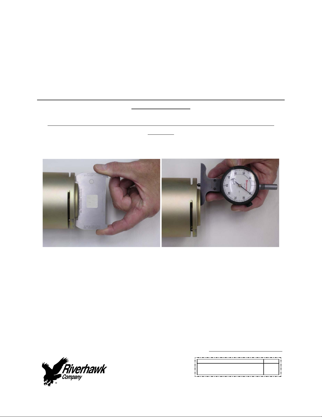
Thestick‐outlengthcanbecheckedthreedifferentways.
Stick‐OutGageDropGage

Instruction Manual IM-278
CUSTOMER'SINFORMATIONBOX
CONTENTSAREINDEPENDENTOFRIVERHAWKDOCUMENTCONTROL
215ClintonRoad
NewHartford,NY13413
Tel:+13157684855
Fax:+13157684941
Email:[email protected]
REV
373A4054
GEDRAWINGNUMBER
RevisionA
Page17of32
DigitalCalipers
SamplePicturesofaStick‐OutMeasurement
7.0AssemblyofTensioneronStud
Alltensioningwillbeperformedfromtheconicaltensioningthreadendofthestudwith
orientationofthestudtotheflangeasshowninFigures1thru4.
7.1AssemblyofTensionerKitwithORANGESafetyGuard
RefertoTensionerdrawingandFigure6fortensionertoflangemounting.Assemblysequenceisas
follows:
1. Carefullycheckthecleanlinessofboththestud'sandthepullerscrew'sconicalthreads.
2. Ensurestudlengthmeasurementisdocumented.
3. Verifystickoutlengthofstudtonut.
4. Applyalightcoatofcleanturbineoiloraspraylubricanttothepullerscrew.Donotuse
“NeverSeize”ontheconicalthreads.
5. Placethespannerringontothenut
6. Insertthepullerscrewintothetaperedthreadofthestudandhandtighten.Besurenotto
cross‐threadtheassembly
7. UsinganAllenwrenchtightenpullerscrew,thenbackoffpullerscrew1/2aturn.
8. Retightenpullerscrewbyhanduntilitisfullyinserted.DONOTBACKOFFPULLERSCREW.
9. Placethefootoverpullerscrew,orientateintoposition.

Instruction Manual IM-278
CUSTOMER'SINFORMATIONBOX
CONTENTSAREINDEPENDENTOFRIVERHAWKDOCUMENTCONTROL
215ClintonRoad
NewHartford,NY13413
Tel:+13157684855
Fax:+13157684941
Email:[email protected]
REV
373A4054
GEDRAWINGNUMBER
RevisionA
Page18of32
10. Threadtensionerontopullerscrew.Note:Internalstopintensionerwillresultingapwith
foot.DONOTTIGHTENTENSIONERAGAINSTFOOT.(GAPSHOULDBE1/16”to3/16”)
11. Placeguardovertensionerandpositionguidepinintohexendofstud.
12. Tightenknurledinterlockfittingbyhanduntilitfirmlypressesagainsttensioner.(nogap)
13. Activatecustomconnectorfromrearofguardbypushingonthecenterwithyourthumband
pullingthetabswithyourforefingerandmiddlefinger.Pushtheassemblyforwarduntilit
locksontothetensioner.Releasefingersfromtabsandthenremovethumb.Ensure
connectionisfirmlyengagedorelsethetensionerwillnotbeconnectedtopump.(Figure5)
Figure 5 – Activation of
custom connector

Instruction Manual IM-278
CUSTOMER'SINFORMATIONBOX
CONTENTSAREINDEPENDENTOFRIVERHAWKDOCUMENTCONTROL
215ClintonRoad
NewHartford,NY13413
Tel:+13157684855
Fax:+13157684941
Email:[email protected]
REV
373A4054
GEDRAWINGNUMBER
RevisionA
Page19of32
CAUTION
Personalinjuryandequipmentdamagecanoccurifthepullerscrewisnotsecurelyengaged
withtheconicalthreadsofthestud.Properengagementisachievedwhenthepullerscrewis
tightinthestudandisnotcross‐threadedintotheconicalthread.
8.0StudPullingandTensioning
Thestudswillbetensionedintwosteps,at50%pressureandatfinalpressure.Followthe
tensioningsequenceforeachflangejointasdefinedonthedatasheetsfoundattheendofthis
manual.
Note:Beforethreadingthepullerscrewintothestud,carefullycheckthecleanlinessofboththe
stud'sandthepullerscrew'sconicalthreads.Applyalightcoatofcleanturbineoiloraspray
lubricanttothepullerscrew.Donotuse“NeverSeize”ontheconicalthreads.Thisprocedurewill
easeassemblyandassurepositivematingofthethreadsbeforetightening.
WARNING
ThesafetyguardMUSTbeinplaceandhandskeptoutofdesignatedareasatalltimeswhenthe
tensionerispressurizedotherwisepersonalinjurycanoccur.
Figure 6 – Cutaway View of
Tensioner Installed on Flange

Instruction Manual IM-278
CUSTOMER'SINFORMATIONBOX
CONTENTSAREINDEPENDENTOFRIVERHAWKDOCUMENTCONTROL
215ClintonRoad
NewHartford,NY13413
Tel:+13157684855
Fax:+13157684941
Email:[email protected]
REV
373A4054
GEDRAWINGNUMBER
RevisionA
Page20of32
8.1Tensioningat50%pressure
Afterthetensionerisproperlyinstalledapplyhydraulicpressuretothetool.Bringthepressureto
the50%levelinaccordancewiththefollowingtable.
FlangePosition StudSize 50%Pressure 50%Stretch
TurbinetoCoupling 2‐3/4"
[71mm]
10000psi
[690bar]
Donotmeasure
Donotuse
CouplingtoSubstitute
Shaft
2‐3/4"
[71mm]
10000psi
[690bar]
Donotmeasure
Donotuse
SubstituteShaftto
Coupling
2‐3/4"
[71mm]
10000psi
[690bar]
Donotmeasure
Donotuse
CouplingtoGenerator 2‐3/4"
[71mm]
10000psi
[690bar]
Donotmeasure
Donotuse
8.1.1TighteningofNuts
Tightenthecylindricalnutshandtightusingthepinwrenchandspannerring,asdepictedinFigure
4.Turnthenutuntilitbottomsontheflange.Thenapplytorquetoturnthenutanadditional5
degrees.Thiswillaidinachievingthedesiredstretch.
WARNING:
Keephandsclearofthetoolwhilethepressureisbuildingup.Thisincludesthepinwrenchfor
tighteningthespannerring(nut).Oncethetoolisstabilizedatpressurethenandonlythencan
thenutbetightened.Thisreducesthepotentialofpersonalinjury.
8.2RemovingtheTensionerfromanInstalledStud
Thetensionerremovalistobeaccomplishedbythefollowssteps:
1. Releasethetensionertoolpressurebyopeningthevalveonthepump.Leavevalveopen.(This
isautomaticontheair‐operatedhydraulicpump)Allowapproximately20secondsfor
tensionertofullyretract,thenremovehosefromtensioner.
2. Unscrewknurledfittingattheendoftheguardandremoveguard.
3. Unscrewtensionerfrompullerscrew.Usecautiontoensurethathandsarenotbetween
tensionerandcouplingwhentensionerbecomesdisengagedfrompullerscrew.
Table of contents
Other riverhawk Industrial Equipment manuals

riverhawk
riverhawk IM-164 User manual

riverhawk
riverhawk IM-269 User manual

riverhawk
riverhawk IM-257 User manual

riverhawk
riverhawk IM-150 User manual

riverhawk
riverhawk IM-116 User manual

riverhawk
riverhawk IM-139 User manual

riverhawk
riverhawk IM-477 User manual

riverhawk
riverhawk IM-125 User manual

riverhawk
riverhawk IM-186 User manual

riverhawk
riverhawk IM-255 User manual
Popular Industrial Equipment manuals by other brands


Festo
Festo KES-MC-1-SUB-9 Series Assembly instructions

Herzog
Herzog BHP Installation & service instructions

ABB
ABB HT582327 Operation manual

ABB
ABB Power2 550-M44 Operation manual

Parker
Parker Bestobell Valves IOM 002 Installation, operation and maintenance manual

Eaton
Eaton RAMO5 EIP Series Instruction leaflet


