Introduction
Introduction
This set-up procedure describes the
adjustments on the Power Plug for
setting the dead-band, gain and ramp
rate on a non-feedback proportional
valve.
Proportional valves with over-lapped
spools have a range of spool travel
where there is no flow from the valve.
This range of spool motion is called
dead-band. Adjusting the power plug
allows the dead-band to be
electronically eliminated (dead-band
compensation) by making the spool
jump across the dead-band when a
small input signal is applied to the
power plug.
Gain +Output Flow
Input Voltage
The gain of the valve is the ratio of the
opening of the valve (or flow rate from it)
to the applied voltage input to the power
plug.
The ramp rate is the rate at which the
power plug allows the valve to open (or
close) when a step voltage input is
applied to the power plug. In many
applications this ramp would be used
to gradually accelerate or decelerate
an actuator.
Installation precautions to
eliminate leaks into the power
plug
SUse only cables with circular
cross-sections and diameter
between 5–10 mm (.2” - .4”)
SEnsure that sealing grommet is
present and installed correctly. It
must be forced over the outer jacket
of the cable.
SEnsure that all the gaskets are
present and properly seated.
SEnsure that the plastic cover seats
firmly and correctly on the center
body post.
Necessary Equipment
SEHH-AMP-702-D-10 or
EHH-AMP-702-E-10 power plug
SCompatible KDG series or KTG
series non-feedback type
proportional valve
SHydraulic power source and load
circuit
S24 volt DC power source
S10 volt DC power source
SDC voltmeter
S1000 ohm potentiometer
(multi-turn preferred)
SConnecting cables
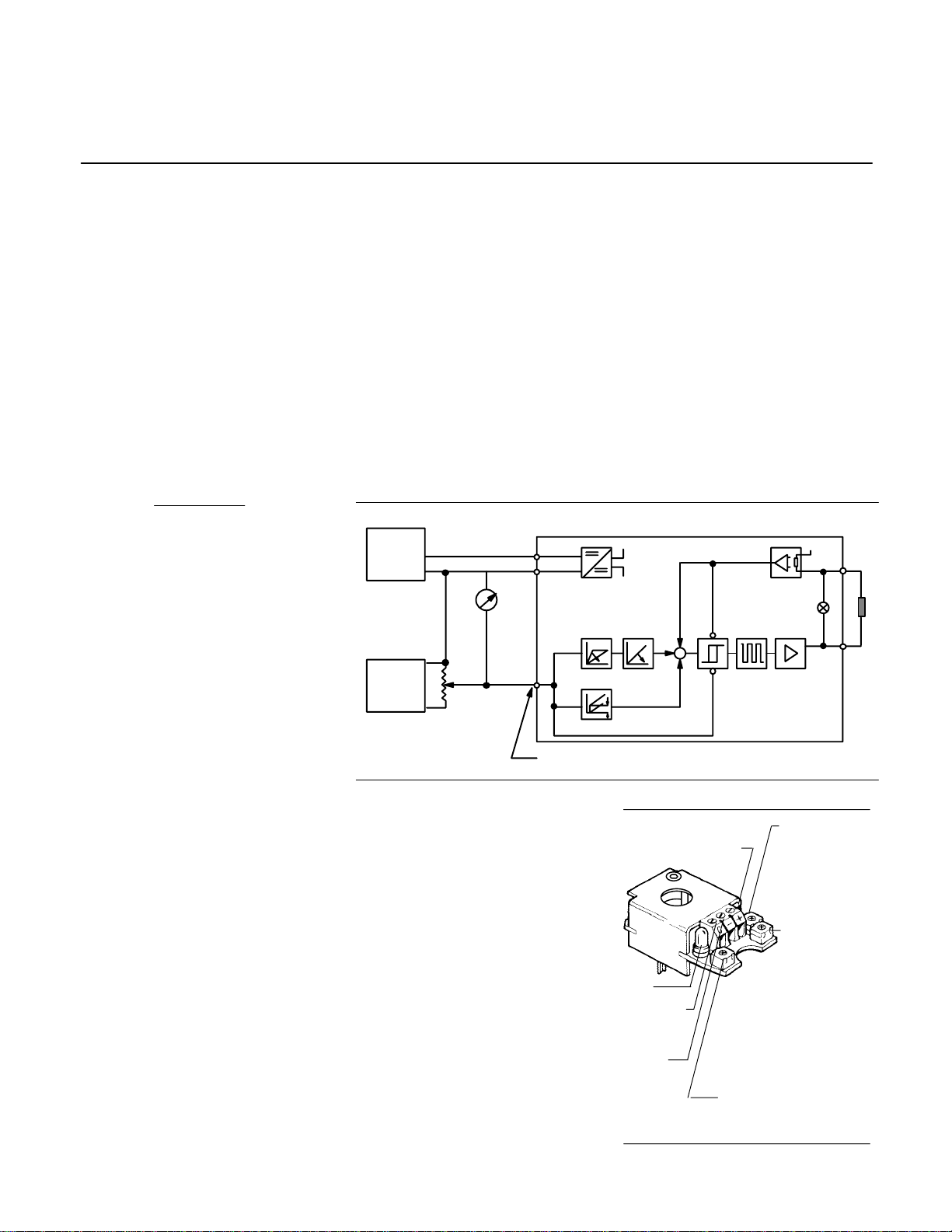
Figure 1. Power plug set-up schematic
Connection of power plug
Referring to the schematic in Figure 1
and the power plug diagram in Figure 2,
connect the power supplies, voltmeter,
command potentiometer and valve
solenoid as shown.
ground
command
signal
input
LED
R1 – Ramp
adjustment.
Turn clockwise
to increase
ramp time.
R3 – Dead-
band
compensation
adjustment.
Turn clockwise
to reduce
deadband
compensation
current.
R2 – Gain adjustment.
Turn clockwise to
decrease gain.
Power input +24V
Figure 2. Power plug connections
EEaton Hydraulics, Incorporated, 2000
All rights reserved
+
–
–
+
+
–
–
+
1000W
command
pot.
volt
meter
Power
input
C
Signal input
R3: deadband
compensation
R1
Ramp R2
Gain
Power plug
Solenoid
Power
amp.
Modulator
Enable
24V DC
10V DC
Power
supplies


 Series Manual")


