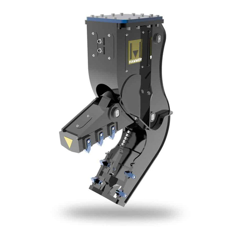
Hammer FR21 User manual

ROTARY CRUSHER
FR 21
INSTRUCTIONS MANUAL

INDEX
DESCRIPTION OF THE ATTACHMENT ___________________________________________ 5
TECHNICAL SPECIFICATIONS _________________________________________________ 5
PURPOSE OF THE ATTACHMENT _______________________________________________ 6
RESPONSIBILITY __________________________________________________________ 7
DEFINITIONS _____________________________________________________________ 7
MOVEMENT AND TRANSPORTATION OF THE ATTACHMENT ________________________ 11
ATTACHMENT INSTALLATION ________________________________________________ 11
ASSEMBLY AND DISASSEMBLY OF THE ATTACHMENT _____________________________ 12
START-UP AND USE OF THE ATTACHMENT _____________________________________ 12
CONNECTION SPECIFICATIONS: ____________________________________________ 13
MAINTENANCE AND REPAIR ______________________________________________ 14
CHANGING THE OIL __________________________________________________ 15
GREASING _________________________________________________________________ 16
INFORMATION REGARDING DISMANTLEMENT __________________________________ 17
DEMOLITION OF THE MACHINE _____________________________________________ 17
INFORMATION OF ENVIRONMENTAL CONCERN __________________________________ 17
ADVICE REGARDING THE PROPER TREATMENT OF WASTE MATERIAL ____________ 17
SPARE PARTS LIST ______________________________________________________ 17
HYDRAULIC SCHEMATIC ___________________________________________________ 18
TIGHTENING TORQUE OF SCREWS AND NUTS _________________________________ 19
EXPLODED VIEW AND PARTS LIST __________________________________________ 21 - 29
2

This instruction manual has been esigne an organize to permit quick an easy consultation via the in ex
or ere by subjects an the explanatory fi gores an tables.
This instruction manual must be stu ie by the owner of the machine, the technical personnel within the
factory, the operators, i.e. all those who use the machine, an the maintenance technician.
The manual is an integral part of the machine an contains information on use, technical characteristics an
instructions for han ling, installation, assembly, a justment an maintenance.
This manual:
- must be consi ere an integral part of the machine until it is emolishe ;
- must be kept in a suitable easily accessible place
- must be consulte whenever problems or oubts arise concerning operation of the
machine;
- must be carefully followe for maintenance operations.
HAMMER SRL reserves the right to up ate the machine an instruction manual accor ing to
technological progress an state of the art.
This constitutes no obligation to carry out mo ifications to the machines that have alrea y been sol .
If the machine is ce e to a thir party, it is recommen e that the instruction manual follow it.
HAMMER SRL RETAINS ITSELF FREE FROM LIABILITY OF ANY KIND, ESPECIALLY FOR:
- improper use of the machine;
- use of the machine by personnel not traine to use it;
- power source efects;
- maintenance efects;
- unauthorize an unforeseen mo ifications;
- use of spares that are not original or not specific for the mo el;
- non observance of the instructions
- possible exceptions
The use of the machine for ifferent purposes are to be consi ere angerous for the operator an for the
machine. Likewise, mo alities of installation an utilization ifferent from that in icate in the present manual
coul cause amage to persons an /or to the machine itself.
3

DECLARATION
THE UNDERISGNED HAMMER SRL
(Manufacturer) Via Oleifici dell’Italia Meridionale
Lotto G1
70056 Molfetta (Ba) – Italia
DECLARES HEREWITH, ON ITS RESPONSABILITY, THAT THE PRODUCT
The Director
Valerio MODUGNO
COMPLIES WITH THE FOLLOWING RULES:
- (EC) DIRECTIVE 2006/42/CE
- EUROPEAN RULES EN 474-1 EN 474-5 EN 12100
4

WARNING: Before carrying out any operations on this product, read this instruction manual
carefully.
DESCRIPTION OF THE ATTACHMENT
This crusher is able to perform both primary an secon ary emolition.
This interchangeable attachment is mounte on excavators esigne for earth-moving vehicles.
TECHNICAL SPECIFICATIONS
A mm 2320
B mm 790
C mm 1040
ROTATION FLOW l/min 20/30
ROTATION PRESSURE bar 70
OPEN / CLOSE FLOW l/min 180/230
OPEN / CLOSE PRESSURE bar 300
ROTATION 360°
WEIGHT kg. 2100
EXCAV. WEIGHT ton 18/26
φMax. CUTTABLE mm 45
5

PURPOSE OF THE ATTACHMENT
The machine is esigne for CRUSHING CONSTRUCTION MATERIALS an CUTTING POSSIBLE internal metal
frames.
The equipment can rotate to reach the correct cutting angle:
ATTENTION In the table " TECHNICAL SPECIFICATIONS" in icates the maximum iameter of the
metal can be cut.
UNAUTHORIZED USES:
NO REPAIR OR MAINTENANCE WHILE THE EQUIPMENT IS
FUNCTIONING
DO NOT OSCILLATE WHILE CUTTING
DO NOT ROTATE THE EQUIPMENT WHILE CUTTING
DO NOT USE VERTICALLY; THERE IS DANGER OF CUT PIECES
FALLING. USE DRIVER’S PROTECTION CAB
DO NOT HIT THE MATERIAL WHILE WORKING
DO NOT PUSH THE MATERIAL WHILE WORKING
6

RESPONSIBILITY
Responsibility for the application of these safety gui elines lies with the in ivi uals in charge of managing the
activities liste below:
-Transport an installation
-A justments
-Operation
-Emergency situations
-Maintenance
-De-commissioning an emolition
These in ivi uals must ensure that all personnel are aware an apply the gui elines within this manual.
Not following safety regulations an gui elines may cause injury an possible amage to the machine or its
components.
SAFETY REGULATIONS
The follow escriptions are inten e to efine a series of performances an obligations, which must be uphel
when performing the activities, liste in the “Responsibilities” section in or er to operate machinery un er
safe con itions for personnel, equipment an the surroun ing environment.
DEFINITIONS
Protection System:
Protection system inclu es all specific barriers, gates, gear-cases, etc., esigne to ensure the integrity of the
machine an the physical safety of the operators.
Operating Personnel:
Operating personnel inclu es all in ivi uals specifically traine an elegate to the management an
operation of the activities liste in the “Responsibilities” section.
Transport and Installation:
Transport refers to any movement of the machine, or parts of it, performe manually or using specific
han ling evices.
Installation is the mechanical an electrical assembly of the machine in a pro uction environment an
a heres to the safety regulations of both the attachment an the excavator.
Emergency Situation:
Emergency situations are the events or series of events that require the imme iate stoppage of machine
operation.
Maintenance:
Maintenance involves operations such as cleaning, verification an perio ic replacement of machinery
components to ensure correct an safe operation.
De-commissioning and Demolition:
De-commissioning involves the mechanical an electrical removal of the machine from a pro uction
environment.
Demolition involves the isassembly an isposal of machine components.
Incorrect Use:
Incorrect use means the utilization of the equipment outsi e the limits specifie in this technical manual.
Work Area:
The work area is the area where machine operations are performe
7

APPLICATION VALIDITY OF SAFETY REGULATIONS
Never operate an excavator without safety guar s installe . Safety glass an wire mesh cab guar ing must be
installe to protect the operator from flying ebris that may be create uring processing.
Falling object protection structures or fops are require for any application where material is to be han le
overhea . Avoi han ling material overhea whenever possible.
Keep all parts of the machine at least 16 m (50 ft) away from power lines.
All local, state/provincial an fe eral regulations must be met before approaching power lines, overhea or
un ergroun cables, or power sources with any part of the excavator.
Do not operate the machine near energize power lines.
Always contact the electrical company when operating near power lines, power lines shoul be move ,
insulate , isconnecte or e-energize an groun e before operating in the area.
Equipment operation an maintenance practices irectly affect you safety an the safety of those aroun you.
Always use common sense while operating an be alert to unsafe con itions.
Do not operate if there are unsafe con itions. Stop operation imme iately, shut own the machine an report
the unsafe con itions to the proper authority.
Excavators in overhea emolition or high reach applications must have prioritize oil flow to their main
valves.
Machines require high volumes of oil at lower pressures to open an close the jaw in the non-cutting mo e.
In the event of a buil ing or structure collapse, if the excavator ies not have prioritize flow, opening the jaw
will ren er all other functions such as boom an tracking slow or inoperable because the oil will take the path
of least resistance, which is the shear function. Although this is not a common situation, it is something that
shoul be a resse with your excavator ealer prior to machine installation.
The machines are size for excavator stability when properly operate . However, improper operation, faulty
maintenance or unauthorize mo ifications may cause instability. Know the working ranges an capacities of
the excavator to avoi tipping. Always use the recommen e counterweight.
The following con itions affect stability:
Groun con itions
Gra e
Weight of attachment
Contents of attachment
Operator ju gment
8

Before the operation
Warn all others in the area that you are about to start operation.
Check un erneath an aroun the machine for obstructions. Make sure that all personnel an equipment are
clear form the area of operation.
Check clearances in all irections, inclu ing overhea .
Be properly seate in the operator’s seat.
Operating personnel in the work area MUST ALWAYS wear suitable clothing such as:
- Protective footwear
- Suitable work coveralls
- Protective gloves
- Hearing protection
- Har hat
- Safety glasses
•Personnel must not eat or rink in works areas.
•Personnel must not smoke cigarettes in work areas.
•Personnel must not operate machinery un er the influence of rugs or alcohol.
Do not wear loose clothing or jewelry that coul get caught on the machinery an cause injury.
Keep han s, feet, hair an clothing away from moving parts.
Keep han s an feet within the operator’s platform.
Know the pinch an crushing points as well as all rotating components an avoi them uring operation.
Always know where to get assistance in case of an emergency. Know where to locate an how to use safety
equipment, such as a first ai kit an fire extinguisher.
Report all injuries to your supervisor or as irecte .
Before performing any of the activities liste in the “Responsibilities” section, make sure that:
- There are no unusual or potentially hazar ous con ition an that no unauthorize personnel are present in
the work area.
- There are no materials in the work area that may obstruct or impe e visibility.
- All protection systems are correctly install an operational.
- Make sure that the ambient an working temperatures o not excee the permitte limits of -16°C to +45°C
(3°F to 113°F). If working in temperatures below 3°F (-16°C) it is very important to operate the shear
without cutting material to increase internal temperature. To ensure the hy raulic oil reaches normal working
temperature, open an close the jaw 10 times slowly.
9

Check the Equipment
At the beginning of each shift, take the time to check the equipment an have all systems in goo operational
con ition.
Check the following:
•Ensure all warning ecals, special instructions an operator’s manuals are legible an in their proper
locations.
•All grease fittings have been grease .
•Check bla es an wear surfaces for wear or amage.
•All flui levels.
•Hy raulic connections. Repair or replace any amage hoses or connections.
•All controls levers for proper operation.
•Rotation bearing. Visually check for loose or amage bolts.
Know the Work Area:
Check clearances in the work area. Keep all bystan ers at a safe istance. Do not work un er obstacles with
the working range of the shear. Check the location for overhea an burie power lines or other utilities
before operation.
Know the Rules:
Most employers have rules for proper operation an maintenance of the equipment. Before starting work at a
new location, ask your supervisor or safety coor inator about rules you are expecte to follow. Un erstan
traffic rules at your jobsite. You must recognize an un erstan all signs, flags an markings.
10

MOVEMENT AND TRANSPORTATION OF THE ATTACHMENT
Please see the above escription of the attachment in this manual for an in ication of weights an sizes.
Given the attachment's weight an size, it must be move an transporte only by specifically traine
personnel.
If the operator employe to move the attachment oes not have a complete view of the attachment to be
move , the assistance of a secon operator is nee e on the groun but outsi e of the earth moving vehicle's
range of action.
The attachment has holes for the insertion of lifting hooks. Make sure that these hooks are secure firmly to
allow you to procee to move the attachment.
The hooks and cables used for movement must be of the appropriate size for the weight of the
attachment.
ATTACHMENT INSTALLATION
CAUTION: Before installing the attachment, carefully examine the attachment to ensure that it is intact, as it
may have been amage uring transportation.
It is especially important to check that the pipes an the hy raulic connections are intact...
IMPORTANT: THE OPERATING MACHINE MUST BE CLOSED-CENTERED.
The attachment must be installe in a space large enough to allow the necessary operations to be carrie out
in complete safety.
CAUTION: The attachment must not be use at temperatures below -16 °C or above 45 °C.
11

ASSEMBLY AND DISASSEMBLY OF THE ATTACHMENT
CAUTION: While being assemble , the attachment must be place securely on the groun with the
excavator’s engine at a stan still an parking brakes engage .
If our attachment is supplied without attachment couplings, the client is responsible for fitting it
with appropriate couplings complying with current safety standards.
The installer, operator, an maintenance personnel must wear the appropriate safety evices specifie by the
safety regulations in effect in the country where the equipment is use .
HAMMER SRL enies any liability in the event of acci ents if the installer, operator, an maintenance
personnel fail to use the appropriate safety evices.
Assembly:
The couplings provi e on our attachment are equivalent to those supplie for the stan ar buckets of the
vehicle on which this attachment is mounte . For a etaile explanation on the means of mechanical
connection please refer to the instruction manual of the vehicle in question.
The hy raulic system is connecte by attaching the two hy raulic attachments provi e on the equipment to
the correspon ing attachments on the machine.
This operation is carrie out for the attachments of the equipment rotating system as well as for those of the
opening an closing system.
ATTENTION:
THE ROTATION SYSTEM must be connecte to ONE DELIVERY AND TO ITS RESPECTIVE RETURN.
THE OPENING/CLOSING SYSTEM must be connecte to ONE DELIVERY AND TO ITS RESPECTIVE RETURN.
KEEP THE TWO SYSTEMS CAREFULLY SEPARATED.
CAUTION: THE OUTLET PRESSURE OF THE EXCAVATOR MUST ALWAYS BE AS REQUIRED FOR THE
ATTACHMENT IN USE.
DO NOT USE THE ATTACHMENT WITHOUT FIRST CHECKING THAT THE DELIVERY PRESSURE OF
THE ATTACHMENT IS AS REQUIRED.
Disassembly:
When isassembling, the attachment must be place securely on the groun .
a) Turn off the excavator engine an engage the parking brakes
b) Ensure that the hydraulic system connected to the attachment is no longer under pressure
c) Remove hy raulic connections between the excavator an attachment
) Uncouple the coupling pins of the attachment as escribe in the excavator instruction manual.
START-UP AND USE OF THE ATTACHMENT
During work the operator must stay on the excavator in the position recommen e by the manufacturer.
No one may park within 30 meters of the excavator when it is working.
The various attachments are couple with the operator in his working position on the excavator an no one
may park within 30 meters of the attachment coupling position.
12

CONNECTION SPECIFICATIONS:
With reference to the iagram below:
Dimension A
Dimension B
ROTATION FLOW l/min
ROTATION PRESSURE bar
OPEN / CLOSE FLOW l/min
OPEN / CLOSE PRESSURE bar
A-A B-B hydraulic rotation
opening – closing
1”
3/8”
20/30
70
180/230
300
13

MAINTENANCE AND REPAIR
ATTENTION: ANY OPERATION REQUIRING THE OPERATOR’S DIRECT INTERVENTION (INSPECTIONS,
MAINTENANCE) MUST CARRIED OUT WITH THE OPERATING MACHINE STOPPED, THE MOTOR TURNED
OFF, AND THE PARKING BRAKE ENGAGED. OUR EQUIPMENT MUST ALSO BE PLACED SECURELY ON THE
GROUND.
ATTENTION: THE INSTALLER, OPERATOR AND MAINTENANCE PERSONNEL MUST WEAR THE
APPROPRIATE SAFETY DEVICES SPECIFIED BY THE PERTINENT SAFETY LEGISLATION IN EFFECT IN THE
COUNTRY WHERE THE EQUIPMENT IS USED.
ATTENTION: HAMMER SRL DENIES ALL LIABILITY IN THE EVENT OF ACCIDENTS IF
THE INSTALLER, OPERATOR OR MAINTENANCE PERSONNEL FAIL TO USE THE APPROPRIATE SAFETY
DEVICES.
ATTENTION: MAINTENANCE AND REPAIR OF THE ATTACHMENT MAY BE PERFORMED ONLY BY QUALIFIED
PERSONNEL.
CAUTION: Thin sprays of high pressure hydraulic liquid can penetrate skin. DO NOT use
your finger to search for any leaks. DO NOT place your face near suspected leaks. To find
signs of hydraulic leaks, place a piece of cardboard close to the suspected leaks and then
inspect the cardboard itself. Should the hydraulic fluid penetrate your skin, immediately call
for medical help.
For safe work, it is extremely important for careful inspections an maintenance to be performe regularly as
follows:
EVERY TIME THE MACHINE IS USED:
Control the integrity of attachment.
Check the integrity of the pipes an the connection of the hy raulic attachments.
EVERY 40 HOURS OF EQUIPMENT USE:
Check that the screws are un amage an securely tightene accor ing to the table attache at the en of
this manual.
•With reference to UNI ISO 06, THE LEVEL OF FLUID CONTAMINATION MUST BE CLASS
19/15 OR BETTER ;
•With reference to ISO 16889, THE FLUID MUST FEED THE CYLINDER BY PASSING THROUGH
A PRESSURIZED FILTER with features in compliance with UNI ISO 77 ;
•The temperature of the oil in use MUST NEVER EXCEED 70 °C .
CAUTION: In case of attachment break own, contact the manufacturer irectly or use skille personnel.
Do not mo ify the attachment or its functionality in any way.
14

CHANGING THE OIL
The oil must be change for the first time after 100 operating hours an afterwar s every 2500 hours or
at least every 12 months. These perio s may be varie case by case accor ing to the
actual operating con itions. On changing the oil, we recommen washing the insi e of the casing with the
appropriate liqui recommen e by the lubricant manufacturer. To avoi leaving a slu ge eposit, the oil
shoul be change when the gear motor is hot. We recommen checking the oil level. If more than 10% of
the oil nee s to be a e , thoroughly check that the unit is not losing oil. Avoi mixing ifferent types of oil,
either of the same or ifferent bran s. Avoi mixing mineral an synthetic oils.
DRAINING THE OIL
Place a container un er the rain plug.
Unscrew the rain plug an rain all the oil.
To assist rainage, perform the operation with the gear motor still hot.
Reattach the rain plug.
FILLING
Unscrew the filler cap.
Pour in 2.2 kg of oil (to top it off, pour enough oil to fill the gear motor).
Reattach the filler cap.
15

GREASING
EVERY 8 HOURS OF OPERATION, GREASE POINTS B WITH 4-5 SQUEEZES OF THE GREASE GUN. MOVE
AWAY FROM THE EQUIPMENT, USE THE EXCAVATOR OPENING AND CLOSING CONTROLS TO CLOSE AND
OPEN THE JAWS 3-4 TIMES, THEN GREASE AGAIN.
EVERY 0 HOURS OF OPERATION, GREASE THE ROTATION MOVEMENT AT POINT A. SQUEEZE THE
GREASE GUN 3/4 TIMES. MOVE AWAY FROM THE EQUIPMENT AND USE THE EXCAVATOR CONTROLS TO
ROTATE IT FOR 10 SECONDS, THEN GREASE AGAIN.
EVERY 0 HOURS OF OPERATION, GREASE THE ROTATION MOVEMENT AT POINT C. SQUEEZE THE
GREASE GUN 3-4 TIMES. MOVE AWAY FROM THE EQUIPMENT AND USE THE EXCAVATOR CONTROLS TO
ROTATE IT FOR 10 SECONDS, THEN GREASE AGAIN.
WARNING: MORE FREQUENT LUBRICATION IS RECOMMENDED IN THE TROPICS AND IN ENVIRONMENTS
THAT ARE VERY HUMID, DUSTY, OR WITH SIGNIFICANT LEVELS OF IMPURITIES OR EXTREME
TEMPERATURE FLUCTUATIONS.
16

INFORMATION REGARDING DISMANTLEMENT
DEMOLITION OF THE MACHINE
ATTENTION
If you ever eci e to scrap the machine, you are a vise to ren er it inoperable by ismantling the various
components. All the ismantling process must be carrie out by specialize personnel.
Every time the machine is move aroun on the emolition site, a suitable means of transport must be use ,
with a carrying capacity greater than the weight of the machine.
ATTENTION
Empty the machine completely of all its oil content.
INFORMATION OF ENVIRONMENTAL CONCERN
ATTENTION
Disposal of the packaging materials associate with the machine, as well as substitute parts an lubricants,
must be carrie out with respect for the environment, avoi ing pollution of soil, air an water. It is the
responsibility of the consignee to ensure that the operation is execute in full conformity with the current
regulations of the country where the machine is put to use.
ADVICE REGARDING THE PROPER TREATMENT OF WASTE MATERIAL
•Ferrous material, such as aluminium an copper: to be treate as recyclable
material an taken to an official collection centre.
•Plastic an rubber materials: these materials shoul be taken to the scrap-
yar or official recycling centre.
•Oil waste: to be taken to an official centre for the collection of oil waste, to
be properly estroye .
•Never tip oil waste into rains, rivers etc.
•Never ischarge oil waste straight onto the groun .
•Comply fully with the laws an regulations regar ing the treatment of
angerous substances such as oil, fuel, solvents use filters an batteries.
SPARE PARTS LIST
In the following sheets you will fin the explo e rawings referring to the various spare parts an the list
with the escription of the single pieces.
ATTENTION : to or er the right spare parts it is necessary to in icate the kin of equipment an its serial
number. Please sen also the rawing pointing out the piece you nee .
17

HYDRAULIC SCHEMATIC
18

TIGHTENING TORQUE OF SCREWS AND NUTS
The tightening torque in the table are vali approximately for the following con itions :
-Hexagonal- hea screws (UNI 5737 type), cylin rical-hea screws (UNI 5931 an UNI 6107 type).
- The tightening torque must be applie slowly with ynamometric wrenches.
-The iagram is base on a static coefficient of friction µ = 0.14. For a ifferent friction coefficient µx, the
value of the clamping force etecte by the iagram must be multiplie
for the correction factor.
x
k
µ
14.0
=
1 Nm = 0,102 kg m
The ata in the table refer to Regulation DIN 267
Ø bolt hexagon
coarse fine coarse fine coa rse f ine coarse fine
mm mm mm Nm Nm Nm Nm Nm Nm
M8 13 1,25 1,0 25 27 35 38 42 46
M10 17 1,5 1,25 50 53 70 74 84 89
M12 19 1,75 1,5 85 89 119 125 143 150
M14 22 2,0 1,5 135 148 190 208 228 250
M16 24 2 1,5 212 226 298 318 357 382
M18 27 2,5 2,0 290 310 402 436 490 523
M20 30 2,5 2,0 413 436 580 614 697 736
M22 34 2,5 2,0 568 597 798 840 958 1.008
M24 36 3,0 2,0 714 781 1.004 1.098 1.204 1.317
M27 41 3,0 2,0 1.050 1.139 1.477 1.602 1.772 1.923
M30 46 3,5 2,0 1.429 1.590 2.009 2.236 2.411 2.648
M33 50 3,5 2,0 1.941 2.136 2.729 3.004 3.275 3.605
M36 55 4,0 3,0 2.497 2.652 3.511 3.730 4.213 4.476
NORM
8.8
10.9
12.9
Metric Thread Metric Thread Met ric Thread Metric Thread
19

20
Table of contents
Other Hammer Tools manuals
