Hakko Electronics FR-400 User manual

Table of Contents
...................... 1
................................................. 1
................. 2
...................................................... 3
.......................................................... 5
...................................... 13
.................................................. 22
................................. 27
............................................. 29
......................... 30
...................................................... 31
........................................... 34
1. PACKING LIST AND PART NAMES
2. SPECIFICATIONS
3. WARNINGS, CAUTIONS AND NOTES
4. INITIAL SETUP
5. OPERATION
6. PARAMETER SETTING
7. MAINTENANCE
8. CHECKING PROCEDURE
9. ERROR MESSAGE
10. TROUBLE SHOOTING GUIDE
11. PARTS LIST
12. WIRING DIAGRAM
Desoldering Tool
Instruction Manual
●
ThankyouforpurchasingtheHAKKOFR-400DesolderingTool.
PleasereadthismanualbeforeoperatingtheHAKKOFR-400.
Keepthismanualreadilyaccessibleforreference.
●
1
2. SPECIFICATIONS
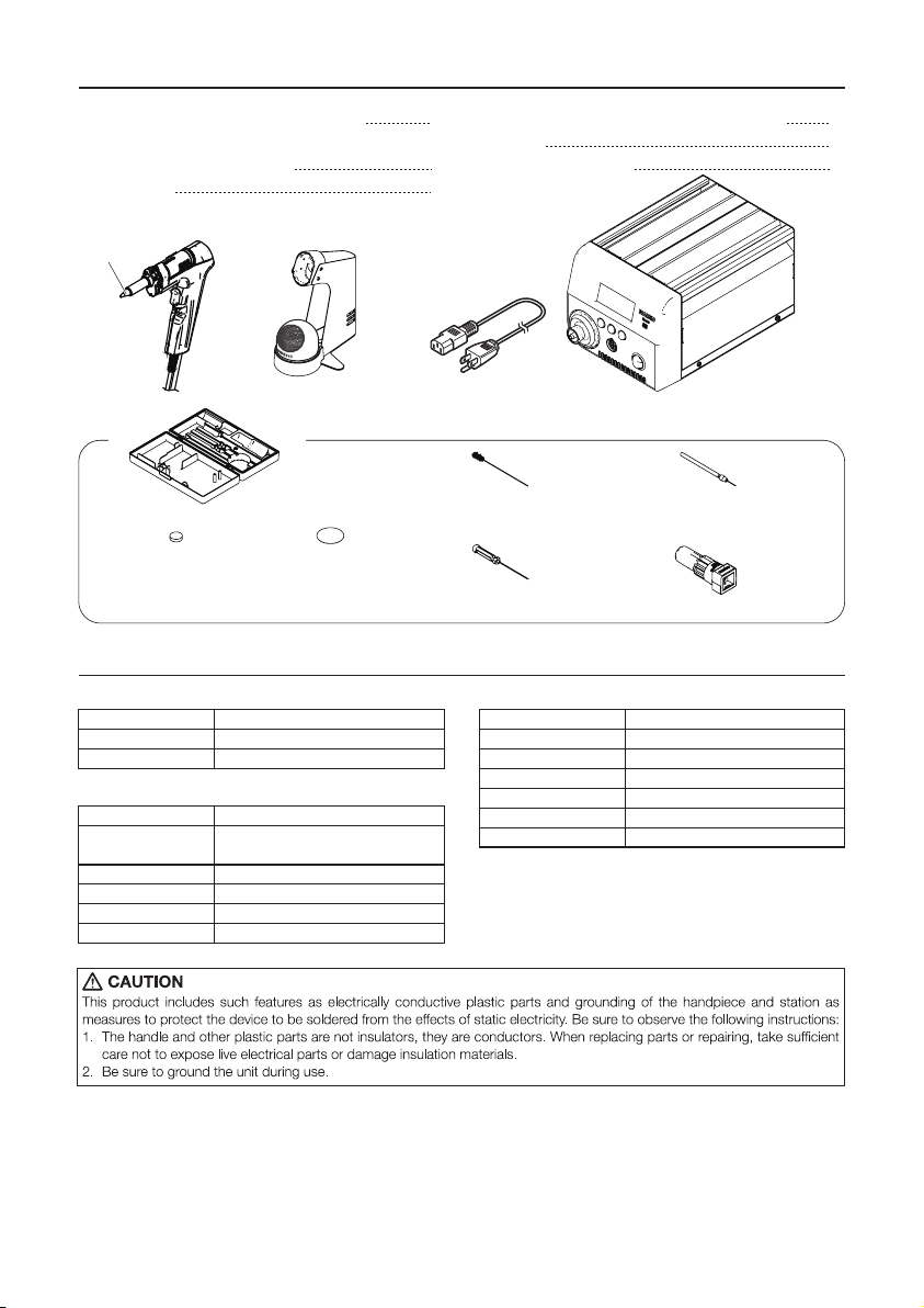
1. PACKING LIST AND PART NAMES
HAKKO FR-400 Desoldering station
HAKKO FR-4001 Desoldering Handpiece
(with ø1.0mm [0.04 in] nozzle)
Power cord
1
1
1
Handpiece holder (with Cleaning wire)
Toolbox
Instruction Manual
1
1
1
CleaningPin(forø1.0mm
[0.04in]nozzle)
Nozzlewrench
CeramicpaperFilter
(Desolderinghandpiece)
Station
Filter CleaningPin
(forHeatingElement)
CleaningDrill(forø1.0mm
[0.04in]nozzle)
● HAKKOFR-400
Power consumption
Temperature range
Temperature stability
320W
350 - 500℃(660 - 940℉)
± 5℃(9℉) at idle temperature
● Station
Output
Dimensions
Weight
Vacuum generator
Vacuum pressure (max.)
Suction flow
AC 29V
160(W) × 137(H) × 235(D) mm
(6.3 × 5.4 × 9.3 in.)
5.7 kg (12.6 lb.)
Vacuum pump, double cylinder type
80 kPa (600 mmHg)
15ℓ/min.
●HAKKOFR-4001
Part name
Power consumption
Nozzle to ground resistance
Nozzle to ground potential
Length (w/o cord)
Weight (w/o cord)
Cord
HAKKO FR-4001
300W(29 V)
< 2 Ω
< 2 mV
183 mm (7.2 in.) with ø1.0mm [0.04 in] nozzle
245 g (0.54 lb.) with ø1.0mm [0.04 in] nozzle
1.2 m (4 ft.)
* The temperature was measured using the HAKKO FG-101
Station Tester.
* This product is protected against electrostatic discharge.
* Specifications and design are subject to change without notice.
HAKKO
FR-4001
Nozzle
(N60 series)
Handpiece holder Power cord
Toolbox
HAKKO FR-400
Station
×1
×1
×1
×1
×2×4
Please check to make sure that all items
listed below are included in the package.
2
3. WARNINGS, CAUTIONS AND NOTES
WARNING
CAUTION
To prevent accidents or damage to the HAKKO FR-400, be sure to observe the following:
● Do not use the unit for applications other than desoldering.
● Do not strike the handpiece against hard objects to remove excess solder. This will
damage the handpiece.
● Do not modify the HAKKO FR-400.
● Use only genuine HAKKO replacement parts.
● Do not allow the HAKKO FR-400 to become wet, or use it when hands are wet.
●
Be sure to hold the plug when inserting or removing the handpiece and power cords.
● Be sure the work area is well ventilated. Soldering produces smoke.
● Be sure the cooling fan at the rear of the station is unrestricted.
● While using the HAKKO FR-400, don't do anything which may cause bodily harm
or physical damage.
When power is ON, the nozzle will be hot. To avoid injury or damage to
personnel and items in the work area, observe the following:
● Donottouchthenozzleorthemetalpartsnearthenozzle.
●
Donotallowthenozzletocomecloseto,ortouch,flammablematerials.
●
Informothersintheareathattheunitishotandshouldnotbetouched.
● Turnthepoweroffwhennotinuse,orleftunattended.
● TurnthepoweroffwhenconnectingtheHAKKOFR-4001or
storingtheHAKKOFM-400.
● Theunitisforacounterorworkbenchuseonly.
● Thisapplianceisnotintendedforusebypersons(including
children)withreducedphysical,sensoryormentalcapabilities,
orlackofexperienceandknowledge,unlesstheyhavebeen
givensupervisionorinstructionconcerninguseoftheappliance
byapersonresponsiblefortheirsafety.
● Childrenshouldbesupervisedtoensurethattheydonotplay
withtheappliance.
Warnings, cautions and notes are placed at critical points in this manual to direct the
operator’s attention to significant items. They are defined as follows:
WARNING:FailuretocomplywithaWARNINGmayresultinseriousinjuryordeath.
CAUTION:FailuretocomplywithaCAUTIONmayresultininjurytotheoperator,
ordamagetotheitemsinvolved.
NOTE:ANOTEindicatesaprocedureorpointthatisimportanttotheprocess
beingdescribed.
3
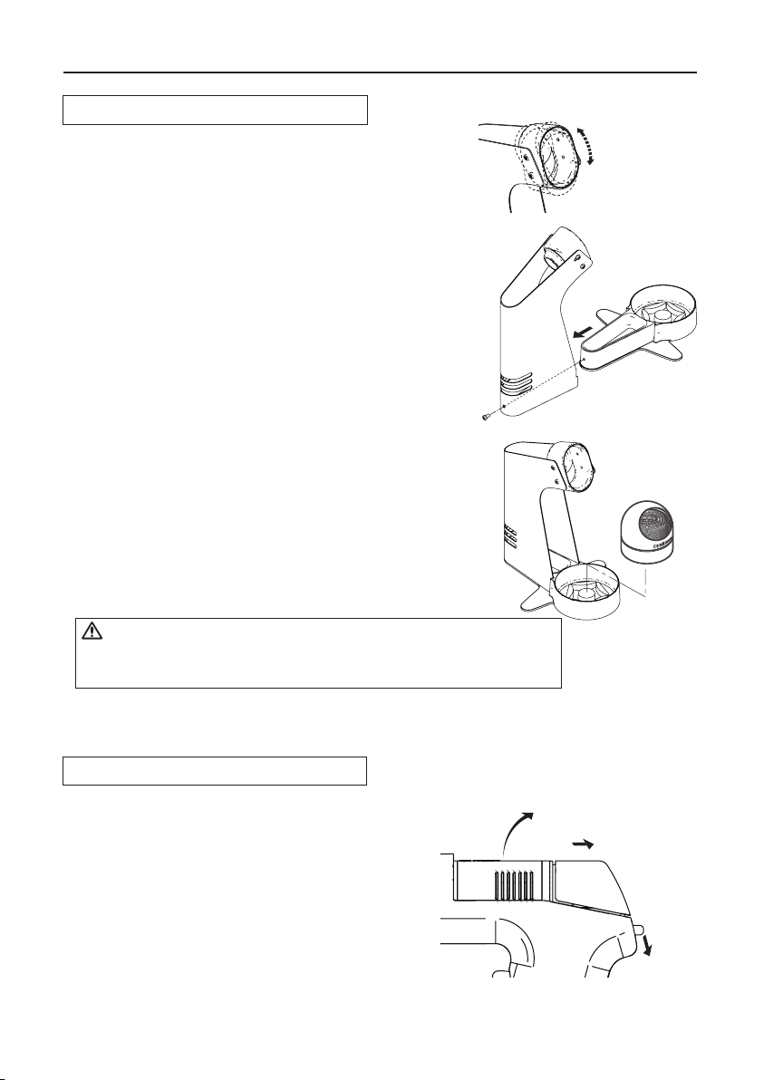
Loosen the adjusting screws to change the angle
of the handpiece receptacle as you like, then tighten
the screws.
4. INITIAL SETUP
A. Handpiece holder
First, remove any excess solder from the nozzle by
thrusting the nozzle into the cleaning wire. (Do not wipe
the nozzle against the wire. This may cause molten
solder to spatter.)
● Operation
Following the instructions given in the illustration
on the right, assemble the handpiece holder.
1. Insert the holder assembly securely into the handpiece
holder base.
2. When the cleaning wire becomes dirty or loaded with
solder, turn the wire until a clean surface is presented.
3. When changing the cleaning wire, lift the top vertically
to prevent solder debris from falling out.
CAUTION
Do not set up the angle of the handpiece receptacle too high, or
the temperature of the handpiece will become very hot.
B. HAKKO FR-4001
● Replacingthefilter
Replace the filter as shown following steps
A to C. During operation, the filter pipe is
very hot. Wait until the filter pipe is cool
before replacing the filter or cleaning.
We recommend keeping a second filter
pipe containing new filters handy, and
replacing the installed filter pipe with this
secondary filter pipe.
B. Pull
A. Down
C. Replace the entire filter pipe with
a secondary filter pipe.

4
3. Set the HAKKO FR-4001 in the handpiece holder.
4. Connect the hose from the HAKKO FR-4001
to the filter case cover on the HAKKO FR-400
station.
5. Plug the power cord into a grounded power outlet.
Ensure that the power switch is OFF before inserting
the AC plug.
CAUTION
Be sure to ground this product as it is ESD
safe by design.
6. Turn the power switch ON.
Turn the power
switch ON
Connect the hose.
C. Station
CAUTION
Be sure to hold the plug when inserting or removing the handpiece cord.
● Connection
1. Connect the power cord to the receptacle on the
rear of the station.
2. Connect the plug from the HAKKO FR-4001
to the receptacle on the HAKKO FR-400.
CAUTION
Connect the plug to the receptacle, aligning
the tab on the plug with the opening on the
receptacle.
Insert the plug into
the receptacle until
it seats.
To disconnect, pull the plug
from the receptacle while
pressing down the tab on
the plug.

5
If you wish to exit the
PRESET SELECTION
screen, simply use the
DOWN button to scroll
to the bottom of the list,
and select <EXIT>.
Control
Button
Receptacle
Filter Case
Cover
PART NAMES
Power Switch
5. OPERATION
Making Changes to Settings
●
Selecting the preset number
If you wish to exit the PRESET SELECTION screen...
•You select <EXIT> and press the <OK> button, you will return to the normal display
without making change.
•if the device is left alone without making any operation for 10 seconds, you will return
to the normal display.
<↓> <OK>
4. Press the “OK” button to
finalize your selection.
<↑>
1. Press any of the
three control buttons.
<↑> <↓> <OK>
PRESET1
PRESET2
PRESET3
350℃
400℃
450℃
2. The preset selection screen
appears.
3.
Make your PRESENT SELECTION
by moving the cursor UP or DOWN
by pressing the corresponding
buttons.
<↓> <OK>
350℃
400℃
450℃
<↑>
C
Normal display screen
PRESET1
PRESET2
PRESET3
350℃
400℃
450℃
PRESET1
PRESET2
PRESET3

6
● Changing various settings
(other than preset selections)
1.
Press and hold any one
of the three control buttons
for at least 2 seconds.
The following settings can be changed from this screen:
Set Temp
Offset Temp
Vacuum Check
Preset Temp
Preset ID
LCD Contrast
<Exit>
(Nozzle temperature setting)
(Nozzle temperature offset setting)
(Check of nozzle clogging and suction force)
(Setting of each preset temperature)
(Setting of each preset name)
(Contrast adjustment of display screen)
(Return to the setting screen)
* Change of selected setting
Depending on selected setting, the display on the screen differs. However, you
can make changes to the settings by following the above operation procedure.
After completing the changes to the setting, if you press the “OK” button again in
the selection screen, you will return to the normal display.
Set Temp
Offset Temp
Vacuum Check
<↓> <OK><↑>
4. Press the “OK” button to
finalize your selection.
2. The setting selection screen
appears.
Set Temp
Offset Temp
Vacuum Check
<↓> <OK><↑>
3.
Make your PRESENT SELECTION
by moving the cursor UP or DOWN
by pressing the corresponding
buttons.
Set Temp
Offset Temp
Vacuum Check
<↓> <OK><↑>

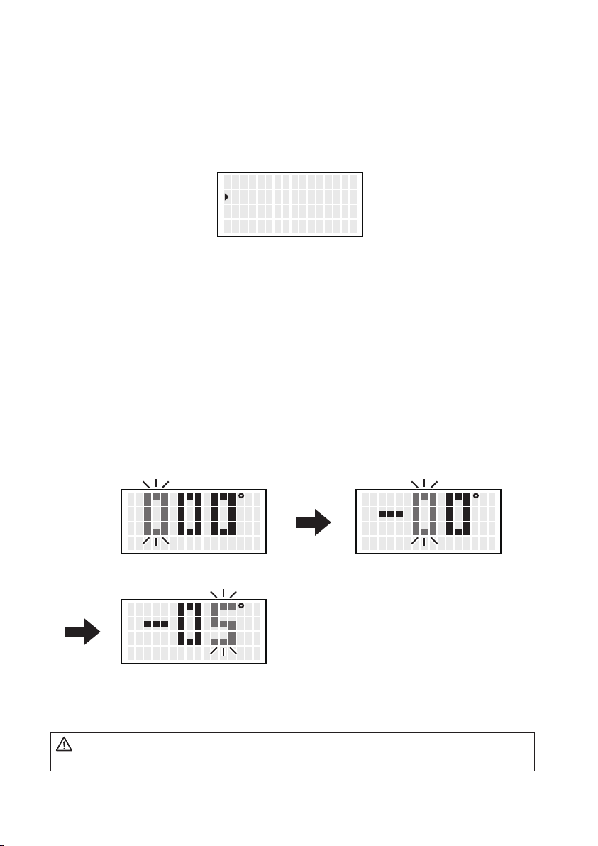
● Set Temp
1. Move the cursor to select “Set Temp”. After selecting, press <OK>.
2.
Entering from hundreds to units digit
Press the <↑> or <↓> to set the desired figure.
Only values from 3 to 5 can be selected when entering the hundreds digit.
(In ℉ mode, values from 6 to 9 can be selected.)
Values from 0 to 9 can be selected when entering the tens or units digits.
(The same values can be selected in ℉ mode.)
3. When desired figure is displayed, press the button to enter.
The next digit will begin to flash. After entering the units digit, press the button to
save the figure to the system memory and begin heater control with new setting
temperature.
CAUTION
The temperature range is from 350 to 500℃. ( 660 to 940℉)
● If you enter a value outside the temperature setting range, the display returns to
the hundreds digit, and you have to enter a correct value.
CAUTION
If power is switched off or lost during the execution of this procedure, no data
will be entered. The entire procedure must be repeated from step 1.
<↑> <↓> <OK>
S e t T emp
O f f s e t T emp
Vacuum Check
350゚ C
00゚ C
C
<↑> <↓> <OK>
C
<↑> <↓> <OK>
C
<↑> <↓> <OK>
7
●Offset Temp
1.
Move the cursor to select “Offset Temp”. After selecting, press <OK>.
2. Enter the offset value (-5) which is the difference between tip temperature and set
temperature.
The hundreds digit can display 0 (for positive value) or minus sign. (for negative value)
(Same values can be selected in ℉ mode.)
Values from 0 to 5 can be selected when entering the ten digit.
(In ℉ mode, values from 0 to 9 can be selected.)
Values from 0 to 9 can be selected when entering the units digit.
(Same values can be selected in ℉ mode.)
The allowable ranges for offset values are from -50 to +50℃ . (In ℉ mode, from -90
to +90℉) If you enter a value outside the offset value range, the display returns to
the hundreds digit, and you have to enter a correct value.
3. After entering the units digit, press the button to save the figure to the system
memory and begin heater control with the new offset value.
CAUTION
During the offset setting, please be careful tip temperature does not exceed 500 ℃.
<↑> <↓> <OK>
S e t T emp
O f f s e t T emp
Vacuum Check
350゚ C
00゚ C
C
<↑> <↓> <OK>
C
<↑> <↓> <OK>
C
<↑> <↓> <OK>
8
Example:If the measured temperature is 405℃ and set temperature is 400℃, the
difference is -5℃. (need to decrease by 5℃) So, enter the figure which 5
is deducted from present offset value.
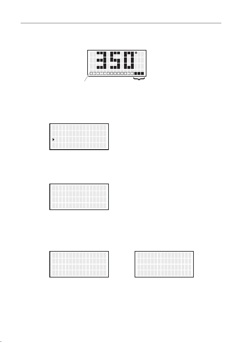
●Vacuum Check
During suction, the gauge indicating sucking status is shown at the lower side
of the screen.
When “CHK” appears and you notice that the sucking force is weakening,
perform “Vacuum Check.”
1.
Move the cursor to select “Vacuum Check”. After selecting, press <OK>.
2.
Pull the trigger.
3. When “Clogging” appears, perform cleaning and replace filters.
C
Suction gauge Sign of clogging
CHK
<↑> <↓> <OK>
S e t T emp
O f f s e t T emp
Vacuum Check
350゚ C
00゚ C
<EXIT>
Vacuum Check
P u ll T r i gge r
<EXIT>
Vacuum Check
P u ll T r i gge r
O K
<EXIT>
Vacuum Check
P u ll T r i gge r
Clo g gin g
No degradation in sucking force Degradation in sucking force
9
Other manuals for FR-400
1
This manual suits for next models
1
Table of contents
Other Hakko Electronics Tools manuals

Hakko Electronics
Hakko Electronics FX-1003 User manual

Hakko Electronics
Hakko Electronics FM-204 User manual

Hakko Electronics
Hakko Electronics FT-8004 User manual

Hakko Electronics
Hakko Electronics 808 User manual

Hakko Electronics
Hakko Electronics 153-1 User manual

Hakko Electronics
Hakko Electronics 394-01 User manual

Hakko Electronics
Hakko Electronics FT-802 User manual

Hakko Electronics
Hakko Electronics FM2023-05 User manual

Hakko Electronics
Hakko Electronics CX1000 User manual

Hakko Electronics
Hakko Electronics CX1001 User manual


