INSTRUCCIONES DE INSTALACION Y FUNCIONAMIENTO PARA
EL CONTROL REMOTO TERMOSTATICO
iADVERTENCIA! DESCONECTE LA ENERGIA EN EL FUSIBLE 0 INTERRUPTOR ELECTRICO
Nota: Las frecuencias de su Receptor y Transmisor han sido fijadas en la labrica. Antes
de instalar el Receptor, asegnrese que el conmutador de interruptores en el Receptor y
Transmisor ester) fijados en la misma frecuencia. (Fig. I). El conmutador de intemmtares
del transmisor se encuentra en el interior del caja de la bateria.
I. PRECAUCIONES DE SEGURIDAD:
•ADVERTENCIA: ALTO VOLTAJE: Desconecte la fuente de energia electrica,
retirando el fusible a desconectando el interruptor electric°.
•No se utilice en ventiladores de estado solid°.
•El cableado electric° debe satisfacer todos los requerimientos del codige local y del
nacional
•La fuente de energia electrica y el ventilador deben ser de 115/120 v, 60 HZ, el motor
del ventilador maxima de 1.0 amps., la !Liz maxima de 300 v.
•La energia electrica domestica puede ocasionar lesiones graves o la muerte.
NOTA: ANTES DE QUE USTED INICIE LA INSTALACTON DE SU NUEVO CONTROL REMOTO,
ASEGURESE DE QUE EL vENT1LADOR ESTA EN LA VELOCIDAD MAS ALTA,
NOTA: Este sistema de control remota es compatible con la mayoria de los ventiladores
para techo, con excepcion de aquellos que tienen el control remoto incorporado en el
interior
NOTA: Este control remoto no esta disefiado pars ventiladores que funcionan hacia
delante o hacia atras, Para que el ventilador funcione hacia atras, primer° detenga el
ventilador y luego cambie manualmente la posiciOn del interruptor de reversa que se
encuentra en el ventilador.
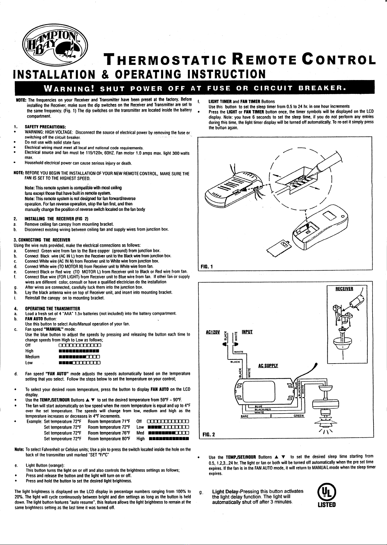
2. INSTALACION DEL RECEPTOR (FIG 2)
a. Retire la cubierta del ventilador para techo de la consola para el montaje.
b. Desconecte el cableado que se encuentra entre el ventilador pars techo y los cables de
suministro de electricidad de is caja de conexiones.
3. CONEXION DEL RECEPTOR
titilice las tuercas para los alambres que se proveen, realice las conexiones electricas
coma se explica a continuacion:
a. Conecte el alambre Verde del ventilador al hilo de Cobre Desnudo (tierra) de la caja de
conexiones.
b. Conecte el alambre Negro (CA en L) del Receptor al alambre Negro de la caja de
conexiones.
c. Conecte el alambre Blanco (CA en N) del Receptor al alambre Blanco de la caja de
conexiones.
d. Conecte el alambre Blanco (AL MOTOR N) del Receptor al alambre Blanco del
ventilador.
e. Conecte el alambre Negro o Rojo (Al. MCYFOR L) del Receptor al alambre Negro o
Rojo del ventilador.
II Conecte el alambre Azul (PARA LA LIJ7.) del Receptor al alambre Azul del ventilador.
En caso de que los alambres del ventilador o los alambres de suministro de energia sean
de diterente color, consulte o Ilame a us eiectricista calificado pars que realice la
instalacion.
g. Despues de que los alambres esten conectados, coloquelos con cuidado dentro de la
caja de conexiones,
h. Coloque el alambre negro de la antena encima del Receptor e introdUzcalo en la
consola pars el montaje.
I. Instale nuevamente la eubierta de la consola pars el tnontaje•
4. FUNCIONAMIENTO DEL TRANSMISOR
a. Coloque 4 plias nuevas de tamafio "AAA" de 1.5 v (no estan incluidas) en el
compartimiento para las baterias.
b. El botan de FAN AUTO:
Utilice este boten para seleccionar el funcionatniento Auto /Manual de su ventilador.
c. El modo de velocidad "MANUAL" del ventilador:
Utilice el baton azul para ajustar las velocidades, presione y suelte el baton cada vez
que vaya a cambiar la velocidad de Alto a Bajo, de la siguiente forma:
Apagado MDCEOMMIDEI
Alto 11111111111111111111111111111•111
Media ••••••••oom
Baja
d. El modo de velocidad del ventilador "FAN AUTO" ajusta automaticamente la
velocidad en la posicion de la temperatura que usted haya seleccionado. Siga las
instrucciones que se dan a continuacion para fijar la temperatura en su control:
•Para seleccionar la temperatura que desea, presione el baton para que la pantalla de
cristal liquid° (LCD) indique FAN AUTO.
•Utilice los botones de TEMP/SET/HOUR [arrow up] [arrow down] para (-Or la
temperatura deseada desde 59°F a 90°F.
•El ventilador arrancara automaticamente en velocidad baja cuando la temperatura de
la habitacian sea igual y este 4°F par encima de la temperatura fijada. Las
velocidades cambiaran desde la velocidad baja, media y alta segUn aumente o
disminuya la temperatura en porciones de 4°F.
Ejemplos: Eije la temperatura a 72°F Temperatura de la habitacion: 71°F Apagado
Fije la temperatura a 72°F Temperatura de la habitacion: 72°F Baja •...MOCEMEI
Eije la temperatura a 72°F Temperatura de la habitacion: 76°F Media NENEERNEEMO
Fije la temperatura a 72°F Temperatura de la habitacion: 80°F Alto •ununnum••u
Nati]: Para seleccionar la temperatura en Celsius o Fahrenheit. Utilice un alfiler pars
presionar el intemmtor sefialado coma "SET 'FPC" queue encuentra dentro de sun
agujero en la parte trasera del transmisor.
e. Baton de la luz (naranja):
Este botOn enciende o apaga la luz y asi mismo controla la intensidad de is
luminosidad, de la siguiente forma:
•Para encender o apagar la luz, presione y suelte el baton,
•Para lijar Is luminosidad de la luz, presione y retenga el beton
I,a pantalla de cristal liquid° (LCD) indica la luminosidad de la luz., la cual se nude en
porcentajes que van desde 100% hasta 20%. El ciclo de Is luz cambiara continuamente
entre las posiciones de luminoso y oscura, mientras se mantenga el baton presionado. El
baton de la luz contiene Is funcion "auto resume-, esta caracteristica permite que Is
luminosidad de Is luz pennanezca en Is rnisma posicion de luminosidad tal cual coma se
utilize la illtima vez antes de apagarse,
f. Los bolt:ones de LIGHT TIMER y FAN TIMER
Utilice cute baton pars fijar el Sleep Timer (Interrupter automatic()) pars intervalos de
tiempo clue van desde 0.5 a 24 hrs. en intervalos de una hors.
•Presione una vez el beton de LicatT o FAN TIMER, la pantalla de cristal liquid°
(I,CD) indicara los simbolos del Timer (Interrupter automatico). Nola: Usted tiene 6
segundos para fijar el interval° de hemp°, si durante este tiempo usted no realiza
mnguna entrada, el interrupter automatic° de la luz se apagara autematicamente. Para
solver a fijarlo, simplemente presione nuevamente el baton.
SUMINISTRO DE AC
Utilice los botones TENI P./SET/HOUR [arrow up] [arrow down] pars fijar el interval°
de tiempo deseado, el cual se iniciara en 0,5, I, 2, 3_24 hrs. La luz a el ventilador, o
ambos se apagaran automaticamente cuando Is programacian original expire. Si el
ventilador esta en mod° de FAN AUTO, volvera al modo MANUAL cuando el interval°
de tiempo expire
gLight Delay-Apretando este buton active
la funcion del retraso de la luz. La luz se
apaga automaticamente despues de tres
minutos.
LISTED