Hamworthy DORCHESTER DR-SG 20-210 User guide

IMPORTANT NOTE
THESE INSTRUCTIONS MUST BE READ
AND UNDERSTOOD BEFORE INSTALLING,
COMMISSIONING, OPERATING OR
SERVICING EQUIPMENT
INSTALLATION, COMMISSIONING AND
SERVICING INSTRUCTIONS
Gas-red condensing water heater
DORCHESTER DR-SG
Models
20-210, 25-210, 30-210,
35-356, 50-356, 60-356,
70-538, 80-538, 100-538, 120-538

Page 2 / 104 00U07337760-A
DORCHESTER DR-SG - Installation, Operation and Maintenance
Technical Enquiries
To supplement the detailed technical brochures, technical advice on the application and use in the Hamworthy Heating range is
available from our technical team in Poole and our accredited agents.
Site Assembly
Commissioning
Service Contracts
Breakdown service, repair, replacement
agents throughout the UK.
Spare Parts
options are available to suit you. Please refer to our website hamworthy-heating.com for more details.
IMPORTANT: NOTE TO THE INSTALLER: LEAVE THESE INSTRUCTIONS ADJACENT TO THE GAS METER.

CONTENTS
............................................................................................................................ 4
1. WARNINGS AND RECOMMENDATIONS...........................................................................5
1.1. Transport and storage ................................................................................................................................... 5
.............................................. 5
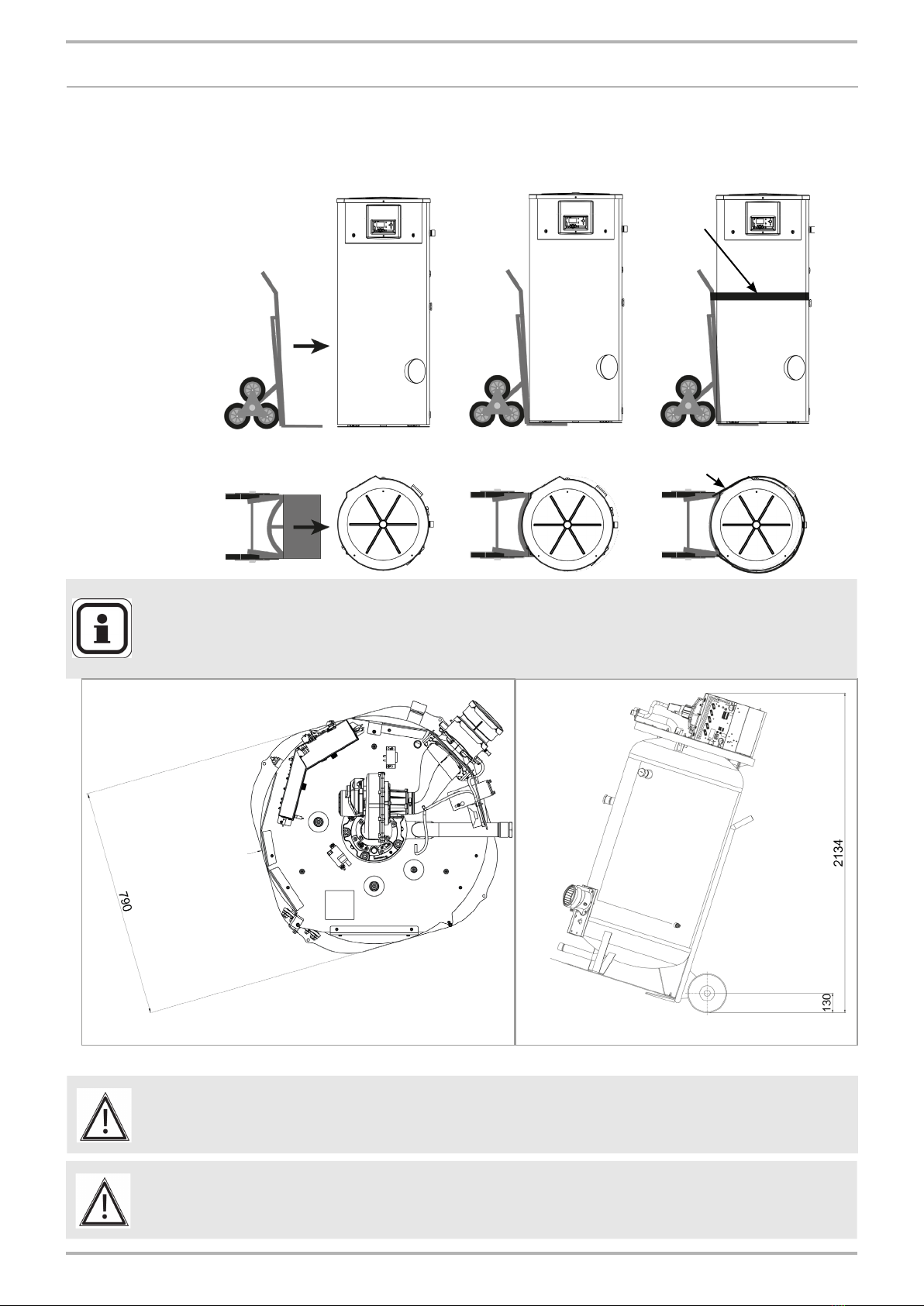
1.3. Handling ........................................................................................................................................................ 6
......................................................................................................................................... 7
1.5. Water composition......................................................................................................................................... 8
2. APPROVALS .........................................................................................................................8
.......................................................................................................... 8
2.2. Gas category............................................................................................................................................... 11
2.3. Gas supply pressures ................................................................................................................................. 11
3. TECHNICAL SPECIFICATIONS ........................................................................................12
................................................................................................................................................. 12
3.2. Boiler components ...................................................................................................................................... 14
3.3. Combustion at 15°C and 1013 mbar........................................................................................................... 16
3.4. Operating conditions ................................................................................................................................... 22
3.5. Electrical connection ................................................................................................................................... 22
4. INSTALLATION ...................................................................................................................23
4.1. Ventilation.................................................................................................................................................... 23
4.2. Unvented installation................................................................................................................................... 23
4.3. Vented installation ....................................................................................................................................... 25
4.4. Removing the cover panel .......................................................................................................................... 26
................................................................................................................ 26
4.6. Flue installation connection......................................................................................................................... 27
4.7. Hydraulic connection................................................................................................................................... 31
4.8. Gas change G20-G31 ................................................................................................................................. 32
4.9. Gas connection ........................................................................................................................................... 37
4.10.Electrical connection / Wiring diagram....................................................................................................... 37
5. START-UP ............................................................................................................................42
5.1. Filling the boiler ........................................................................................................................................... 42
................................................................................................................................................... 42
6. CHECKS AFTER COMMISSIONING.................................................................................42
6.1. Condensate removal ................................................................................................................................... 42
6.2. Gas supply .................................................................................................................................................. 42
7. MAINTENANCE OPERATIONS.........................................................................................43
................................................................................................ 44
7.2. Checking the ignition and ionisation electrodes .......................................................................................... 44
13.01.2023 Page 3 / 104
DORCHESTER DR-SG - Installation, Operation and Maintenance

7.3. Cleaning the condensate evacuation pipe .................................................................................................. 45
7.4. Checking the combustion circuit seal.......................................................................................................... 46
................................................................................................................ 46
7.6. Checking the gas valve setting ................................................................................................................... 47
7.7. Cleaning the burner and the evacuation in the by-pass and changing the seals........................................ 48
8. END OF PRODUCT LIFE ...................................................................................................50
9. HYDRAULIC DIAGRAMS AND CONFIGURATIONS ......................................................51
10. ELECTRICAL VALIDATION...............................................................................................80
11. OPTIMIZATION....................................................................................................................80
12. SPARE PARTS LIST ...........................................................................................................83
13. CUSTOMER REGULATION PARAMETERS TABLE.......................................................92
14. APPENDIX A......................................................................................................................102
INFORMATION: This symbol draws attention to comments.
CAUTION: May cause damage to the installation or to
WARNING:
damage.
DANGER: May cause electrocution.
Symbols used in this document
Page 4 / 104 00U07337760-A
DORCHESTER DR-SG - Installation, Operation and Maintenance

1. WARNINGS AND RECOMMENDATIONS
water storage heater with the mains power on and the casing control cover
removed, all necessary precautions must be taken. The water heater must
.
1.1. Transport and storage
The water heater :
- must be stored vertically at a temperature of between -20 °C and +60 °C,
with a relative humidity of between 5% and 95%.
- must not be stacked,
- must be protected from humidity.
- must not be exposed to the sun.
- must be transported vertically.
- must not be slung.
- must be removed from its pallet for any tilted or horizontal handling. In this
case, the installer will carefully protect the product to avoid any damage
during this handling.
1.2. -
nance
work to be carried out with the power turned on and the casing open.
Basic operations must be carried out with the casing closed.
obligations
13.01.2023 Page 5 / 104
DORCHESTER DR-SG - Installation, Operation and Maintenance

1.3. Handling
The
• Position the three-wheeled hand truck and the strap:
WARNING : Ensure that the DORCHESTER DR-SG is positioned as shown on the
hand-truck in the diagrams above.
IMPORTANT :
To avoid damaging the DORCHESTER DR-SG, we strongly recommend
protecting it where it is in contact with the hand truck and the strap
ratchet..
gure 1 - Transporting through a doorway - Dorchester DR-SG XX-538 model
INFORMATION:
In order to move the DORCHESTER DR-SG XX-538 model through an
800 mm passageway, you will have to dismantle the top, the screen,
covers, and the display support.
Position of the water heater
upon the truck in order to t
through a standard 800mm
doorway
Page 6 / 104 00U07337760-A
DORCHESTER DR-SG - Installation, Operation and Maintenance

1.4.
•
• Check that there are no gas leaks on the installation after any work on the
WARNING:
•
MCV).
•
•
on.
• Ventilate the building by opening doors and windows to ensure an
•
• Where the tightness test indicates a gas escape exists, proceed to
locate and repair the escape.
•
• Where the installation has been proved to be tight and the smell
• Warn occupants and leave the building.
WARNING:
•
7967:2015
WARNING:
operations, make sure that the cables in question are reconnected;
you MUST also reuse the original holding screws.
WARNING:
13.01.2023 Page 7 / 104
DORCHESTER DR-SG - Installation, Operation and Maintenance

1.5. Water composition
a softener to prevent scaling problems in the heating element. Excessive
scaling:
• Reduces device performance
• Can lead to corrosion of the heating element
• The domestic water must meet the following criteria to guarantee the
service life of the appliance:
• Chloride concentration less than 150 mg/L
•
• Total chlorine concentration less than 1 mg/L
It is possible to disinfect the appliance by occasionally implementing what are
called chlorine shocks within the limit of 50 mg/L of chlorine for between 4 to 6
hours. Exposure time should not exceed 24 hours at room temperature.
This disinfection can also be performed using hydrogen peroxide with a
maximum concentration of 30% and an exposure time of less than 24 hours
at room temperature.
2. APPROVALS
2.1. Compliance with European Directives
This product is intended for use only by competent persons.
Children should be supervised to ensure that they do not play with the
appliance..
-
heaters with an output of 400 kW or less are provided in Appendix A.
in appendix A of the installation manual.
Standards
and Regulations
Page 8 / 104 00U07337760-A
DORCHESTER DR-SG - Installation, Operation and Maintenance

appliance is suitable only for installation in GB and IE and should be installed
in accordance with the rules in force.
registered engineer or in IE by a competent person. It must be carried out in
In IE, the installation must be carried out by a Competent Person and installed
Building Regulations and reference should be made to the current ETCI
rules for electrical installation.
- The Building regulations.
Approved document G, Approved document L and Approved document P
and Approved document J
- British standards.
maintenance of chimneys.
provision for gas appliances.
Edition
heating appliances of rated input not exceeding 70 kW net
7074-2 Application, selection and installation of expansion vessels and
medium temperature hot water heating systems
output greater than 45 kW. Fundamental and design considerations
of output greater than 45 kW. Installation, commissioning and maintenance
output greater than 45 kW. Installation, commissioning and maintenance
13.01.2023 Page 9 / 104
DORCHESTER DR-SG - Installation, Operation and Maintenance

water for domestic use within buildings and their curtilages.
of the following:
heating systems.
design heat load
of water based heating systems
Consumption - Part 1: General
water for human consumption - Part 3: Pipe sizing
water for human consumption - Part 4: Installation
water for human consumption - Part 5: Operation and maintenance
of services supplying water for domestic use within buildings and their
maintenance of domestic central heating and cooling water systems
- IGEM publications.
and commercial gas installations
premises
- Additional standards
Electricity at Work Regulations 1989
- Building regulations 2010 approved document B.
Page 10 / 104 00U07337760-A
DORCHESTER DR-SG - Installation, Operation and Maintenance

2.2. Gas category
group H
INFORMATION:
Gas category
II2H3P
II2H3P
II2H3P
2.3. Gas supply pressures
INFORMATION: The pressures provided below must be taken at the inlet to the gas
valve.
Natural gas
H G20
Propane
gas G31
20 37
17 25
25 45
13.01.2023 Page 11 / 104
DORCHESTER DR-SG - Installation, Operation and Maintenance

3. TECHNICAL SPECIFICATIONS
3.1. Dimensions
MODELS
Dorchester
DR-SG XX-210
Dorchester
DR-SG XX-356
Dorchester
DR-SG XX-538
20 25 30 35 50 60 70 80 100 120
1 Hot water outlet Rp 1"1/2 Rp 1"1/2 Rp 1"1/2
2 Secondary return Rp 1"1/2 Rp 1"1/2 Rp 1"1/2
3 Cold water inlet Rp 1"1/2 Rp 1"1/2 Rp 1"1/2
4 Rp 1" Rp 1" 1/4 Rp 1" 1/2
5 Gas inlet R 3/4" R 3/4" R 1"
6 Air inlet Ø 80 Ø 100 Ø 130
7 Fume outlet Ø 80 Ø 100 Ø 130
XX-210 XX-356
6
51
4
2
3
7
6
5
1
4
2
3
7
Page 12 / 104 00U07337760-A
DORCHESTER DR-SG - Installation, Operation and Maintenance

REF Description DR-SG
XX-210
DR-SG
XX-356
DR-SG
XX-538
AOverall Height 1802 1874 2028
B Ø 600 Ø 750 Ø 890
CHeight to cold water inlet 100 100 100
DHeight to inspection hatch 419 454 467
EHeight to secondary return 759 980 1129
FHeight to T&P valve connection 1193 1248 1373
GHeight to gas connection 1508 1580 1735
HHeight to hot water outlet 1514 1579 1748
I 380 402 442
JHeight to air inlet 1691 1752 1871
K 45° 45° 45°
L 13° 15° 70°
MAngle position of gas connection 12.9° 20° 20°
NAngle position of inspection hatch 45° 45° 38°
OAngle position of HMI 90° 90° 90°
P 478 470
QAngle position of lower anode
80° 35°
ROverall width with LPG
conversion kit 639
SAngle position of gas connection
with LPG conversion kit 20°
TWidth 699 884 1020
UHeight to condensate trap outlet 238 235 151
XX-538 G20
XX-538
6
51
4
2
3
7
13.01.2023 Page 13 / 104
DORCHESTER DR-SG - Installation, Operation and Maintenance

3.2. Boiler components
gure 2 - Dorchester DR-SG components
1Control unit
2Ionisation electrode
3Ignition transformer
4
5Upper powered anode
6
7Fan
8Air inlet
9Air valve
10 Air pressure switch
11 Gas valve
12 Gas mixer tap
13
14
1
3
4
7
8
9
10
11
6
512
14
2
13
Electrode details:
Page 14 / 104 00U07337760-A
DORCHESTER DR-SG - Installation, Operation and Maintenance

17
20
15
19
16
18
17
20
19
16
18
15
16 Lower powered anode
17
18 Flue temperature sensor
19
20 Condensate removal siphon
15
Dorchester DR-SG XX-356
Dorchester DR-SG XX-538
Dorchester DR-SG XX-210
13.01.2023 Page 15 / 104
DORCHESTER DR-SG - Installation, Operation and Maintenance

Dorchester DR-SG XX-210
20 kW 25 kW 30 kW
Nominal power Pn kW 21 26.3 31.5
Rated heat input Qn kW 20 25 30
Min heat input Qmin kW 6 6 6
m3/h 2.1 2.6 3.2
CO2value range %2
2
kg/h Qn
Qmin
33.1
7.9
41.4
7.9
49.7
7.9
products circuit °C 100 100 100
the combustion products °C 57 58 60
Exhaust outlet interior diameter mm 80 80 80
Maximum allowable nozzle pressure
Pa 110 170 200
m3/h 25 31 37
mg/kWh 29 29 29
Smoke removal and air inlet type
B23 / B23p / C13 / C33
3.3.
3.3.1. Combustion G20
Page 16 / 104 00U07337760-A
DORCHESTER DR-SG - Installation, Operation and Maintenance

Dorchester DR-SG XX-356
35 kW 50 kW 60 kW
Nominal power Pn kW 37 53 60
Rated heat input Qn kW 35 50 56.6
Min heat input Qmin kW 11.3 11.3 11.3
m3/h 3.7 5.3 6
CO2value range %2
2
kg/h Qn
Qmin
53.3
16.6
79.9
16.6
95.0
16.6
circuit °C 100 100 100
combustion products °C 40.3 50.9 51.6
Exhaust outlet interior diameter mm 100 100 100
Maximum allowable nozzle pressure
Pa 130 200 200
m3/h 44 63 72
mg/kWh 32 32 32
B23 / B23p / C13 / C33
13.01.2023 Page 17 / 104
DORCHESTER DR-SG - Installation, Operation and Maintenance

Dorchester DR-SG XX-538
70 kW 80 kW 100 kW 120 kW
Nominal power Pn kW 73.4 84 105 126
Rated heat input Qn kW 69.9 80 100 120
Min heat input Qmin kW 24 24 24 24
m3/h 7.4 8.5 11 12.7
CO2value range %2
2
kg/h Qn
Qmin
104.4
32.4
118.8
32.4
158.4
32.4
187.2
32.4
circuit °C 100 100 100 100
combustion products °C 56.8 58.8 59.8 59.3
Exhaust outlet interior diameter mm 130 130 130 130
Maximum allowable nozzle pressure
Pa 65 95 155 200
m3/h 88 101 126 152
mg/kWh 39 39 39 39
B23 / B23p / C13 / C33
Page 18 / 104 00U07337760-A
DORCHESTER DR-SG - Installation, Operation and Maintenance

Dorchester DR-SG XX-210
20 kW 25 kW 30 kW
Nominal power Pn kW 21 26.3 31.5
Rated heat input Qn kW 20 25 30
Min heat input Qmin kW 6 6 6
m3/h 0.8 1 1.2
CO2value range %2
2
kg/h Qn
Qmin
21.6
7.2
31.7
7.2
38.2
7.2
circuit °C 100 100 100
combustion products °C 37 53 59
Exhaust outlet interior diameter mm 80 80 80
Maximum allowable nozzle pressure
Pa 120 200 200
m3/h 24 30 36
B23 / B23p / C13/ C33
3.3.2. Combustion G31
13.01.2023 Page 19 / 104
DORCHESTER DR-SG - Installation, Operation and Maintenance

Dorchester DR-SG XX-356
35 kW 50 kW 60 kW
Nominal power Pn kW 37 53 60
Rated heat input Qn kW 35 50 56.6
Min heat input Qmin kW 11.3 11.3 11.3
m3/h 1.4 2 2.4
CO2value range %2
2
kg/h Qn
Qmin
42.8
14.4
63.0
14.4
76.7
14.4
circuit °C 100 100 100
combustion products °C 37.8 48.7 50.8
Exhaust outlet interior diameter mm 100 100 100
Maximum allowable nozzle pressure
Pa 152 200 200
m3/h 42 60 68
B23 / B23p / C13 / C33
Page 20 / 104 00U07337760-A
DORCHESTER DR-SG - Installation, Operation and Maintenance
This manual suits for next models
9
Table of contents
Other Hamworthy Water Heater manuals
Popular Water Heater manuals by other brands

Rinnai
Rinnai HJ Cooper owner's guide

Chronomite
Chronomite INSTANT-FLOW SR Series Get started

Bosch
Bosch TR 6000R Series operating instructions

John Wood
John Wood JW6058 Series Installation and operating instructions

Air Venturi
Air Venturi EZ Fill system manual

clage
clage S 5-U Installation and operating instructions

Honeywell
Honeywell WV4262B installation instructions

A.O. Smith
A.O. Smith Innovo 12-160 Installation, service & maintenance manual

Bradley
Bradley S19-690 Installation

Gabarron
Gabarron GTV Installation, setup, maintenance

Teka
Teka EWH 15 VR1.5 instruction manual

OSO
OSO Dualstream Technical installation manual