GB
52
General
This manual contains
instructions about how
the Handöl 50 series
must be assembled and
installed.
To guarantee the function and safety of the stove we
recommend that it is installed by a professional. Our Handöl
agents can recommend a suitable installer.
Instructions for lighting and use are also supplied with the
stove. Read them carefully and keep them safe for future use.
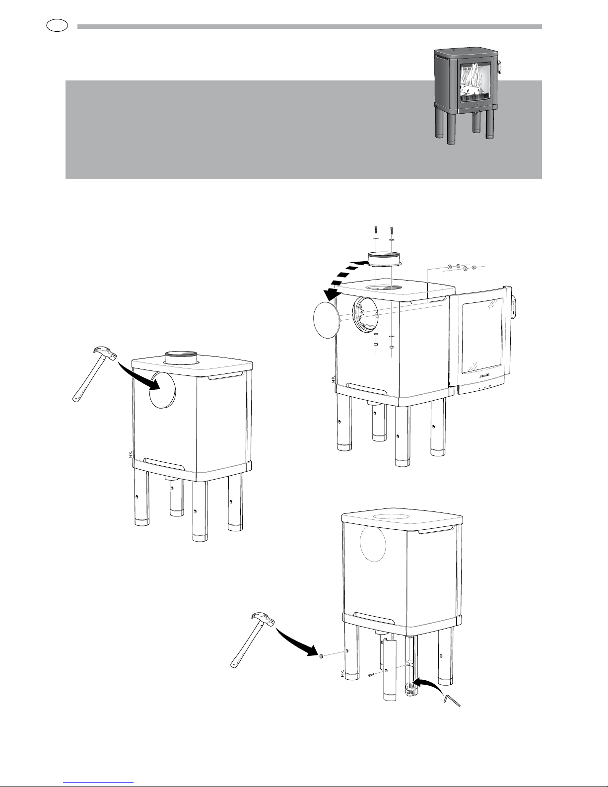
The stove is type approved and must be connected to a chimney
dimensioned for at least 350°C, the external connection
diameter is Ø150 mm. Supply air from the open air should be
used as combustion air.
Building application
Before installing a stove or erecting a chimney it is necessary
for you to apply for planning permission from your local
authority. Ask your local authority for advice regarding building
regulations and the application.
Structural support
Check that the wood joists are strong enough to bear the weight
of the stove and chimney. The stove and chimney can usually be
placed on a normal wooden joist in a single occupancy house if
the total weight does not exceed 400 kg.
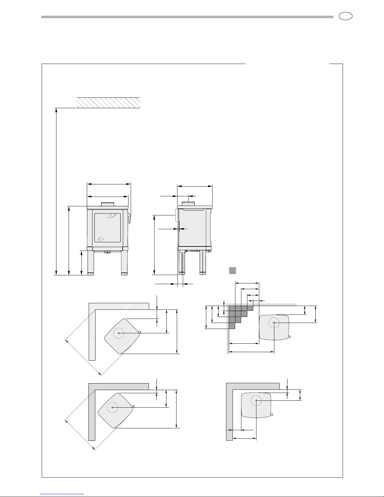
Hearth plate
To protect the floor from any embers the stove must be placed
on a hearth plate. If the floor under the stove is flammable, it
must be protected by a non-flammable material which covers at
least 300 mm to the front and 100 mm on each side.
The hearth plate can consist of natural stone, concrete or 0.7
mm metal. As an accessory, the hearth plate is available in
painted steel.
Chimney
The stove requires a draft in the chimney of at least –12 Pa. The
draught is affected both by the length and area of the chimney,
and by how well sealed it is. Minimum recommended chimney
length is 3.5 m and a suitable cross section area is 150-200 cm²
(140-160 mm in diameter). Carefully check that the chimney is
sealed and that there is no leakage around soot hatches and flue
connections.
Note that a flue with sharp bends and horizontal routing reduces
the draught in the chimney. Maximum horizontal flue is 1 m,
on the condition that the vertical flue length is at least 5 m. It
must be possible to sweep the full length of the flue and the soot
hatches must be easily accessible.
HANDÖL
Inaccordance with standards below
markingwas affixed:
EuropeanStandard:
SEQuality Certification, P-marked:
NOStandard NS 3059:
DKStandard:
DEand AT Standard DIN 18 891
andArt 15a B-VG:
Type:
NominalOutput:
Fuel:
Minimundraught:
Fluegas temerature:
Energyefficiency:
Emissionof CO in cumbustion products:
Distanceto cumbustible wall (mm):
Productionnumber:
Followthe installation instructions.
Useonly recomended fuels
NIBEAB Box 134 SE-285 23 MARKARYD AWEDEN
2006
EN13240
Certno 220316
SINTEF043-xxx
xxxDS/EN13240 plus
XX-91xxxx
H51/H52/H52T
5kW
Wood
12Pa
275°C
79%
0,13%
Behind150
Beside500
Corner150
HANDÖL
NIBE AB SE-8521 Markaryd Sweden
Type:
Production no.
50-series
7090300236
Technical data
Output 3-7 kW
Nominal output 5 kW
Efficiency level 79%
Model 51 52 52T 53 54 54T
Weight (kg) 128 135 172 143 149 190
Width (mm) 495 495 495 550 550 550
Depth (mm) 420 420 420 455 455 455
Height (mm) 825 825 875 825 825 875
The connection’s external diameter is Ø150 mm.
Type approved in accordance with:
European standard EN-13240
Swedish environmental and quality marking,
P-marking cert. no. 22 03 16
Norwegian standard NS 3059, Cert. No xxx-xxx
German standard DIN 18.891, XX-xx xx xxx
Fire-box surround
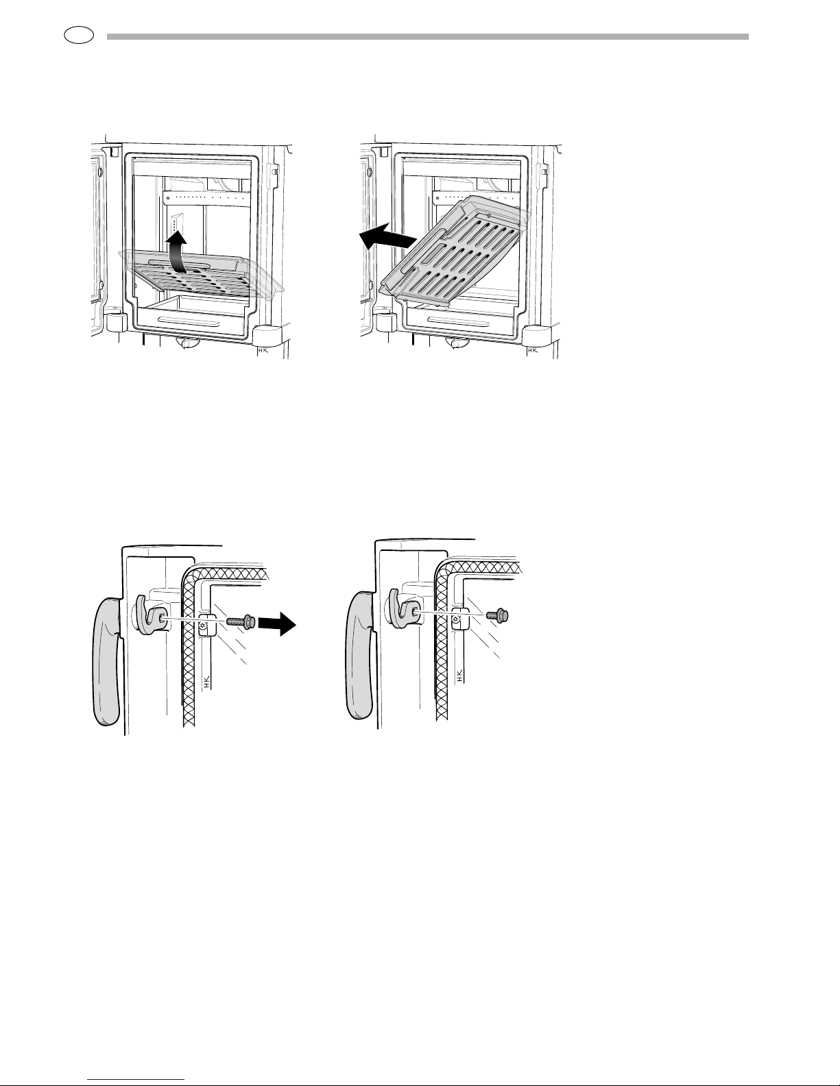
Grate shuttle
Ash-pan
Log guard
Air supply control
Removable handle
Type plate