H&H MFT-HD Operating instructions

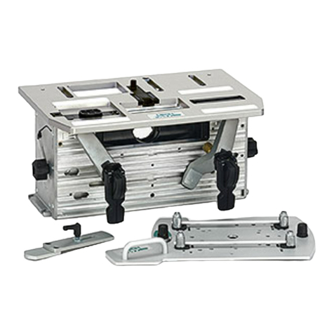
The Miter Mandrel for the MFT-HD has been
engineered to center and lock the tool in a minimum
of pipe depth. It is especially useful for, but not limited
to, elbows.
READ AND UNDERSTAND THESE RECOMMENDATIONS BEFORE ATTEMPTING TO
OPERATE THIS MACHINE!
2. Assemble The Miter Mandrel Gauge
Your Miter Mandrel should have been shipped with
the measuring scales already installed on the gauge
arms. Assemble the Gauge Arms to the Gauge Hub.
Setup
Recommendations for
Model MFT-HD
Miter Mandrel
3. Assemble the Miter Mandrel Body
Measure the I.D. of the pipe to be machined. Select
the appropriate Extension Legs (size range is shown
on the legs). Assemble the Extension Legs by
Installing End Caps onto the legs and threading on
the Jam Nuts (Jam Nuts have a machined flat surface
which must be on the Body side.) Thread the legs in
far enough to fit inside of the pipe.
End Caps Jam Nuts
Body
Gauge Arms Gauge Hub
P.O. Box 393
Wadsworth, OH 44282, U.S.A.
Tel: +1 330 336 4550
Fax: +1 330 336 9159
www.hstool.com
Caution The operation of this machine
and the Miter Mandrel requires heavy
lifts, creates many serious pinch points
and produces metal chips that are
hot and very sharp. All approved safety equipment
must be used for lifting and personal protection. Pay
attention to your surroundings and anticipate where
potentially dangerous, harmful situations are present.
1. Remove Wedge Cone
Remove the six mounting bolts from the wedge cone
and put the cone in the tool box.

4. Assemble the Miter Mandrel
Install the Gauge assembly to the Body assembly,
using four mounting bolts from the wedge cone. The
Gauge assembly must be placed as shown to permit
adjusting and locking the Extension Legs inside the
pipe.
5. Insert the Assembled Mandrel into the Pipe
Insert the Miter Mandrel into the pipe with the Gauge
Arms resting on the pipe edge. Using the Gauge
Scales to center the assembly, turn the Extension
Legs counter clockwise to tighten them against the
wall. Use the 1-1/8" wrench, provided, on the hex
machined into the Extension Legs and tighten them
as tightly as possible. Confirm that the Mandrel is still
centered and use the 2-/14" wrench to tighten the
Jam Nuts to the Body, solidly locking the Extension
Legs in place. We suggest using a soft hammer on the
wrenches on both the Extension Legs and Jam Nuts
to assure that they are completely secured.
Final assembly of the tool on the Miter
Mandrel will require that the operators
place their arms in the space between
the tool and the edge of the pipe. If the
Mandrel is not tightened fully, there is a possibility that
the Mandrel will slip and cause significant injury.
6. Install Alignment Studs
Remove the Gauge assembly and install the
alignment studs provided. These assist in aligning the
tool onto the Mandrel.
7. Installing the Tool —Vertical
When installing this on a vertical pipe (shown), the
tool is lowered carefully until the center shaft flange
contacts the Mandrel. Once the shaft flange is
securely located on the Mandrel, thread two mounting
bolts, used for the wedge cone, into the Mandrel and
gently tighten them. Remove the Alignment Studs,
install the balance of the mounting bolts and tighten
them all securely. The tool is ready to use.

8. Installing the Tool — Horizontal
Mount the Miter Mandrel on to the center shaft using
two mounting bolts from the wedge cone. Suspend
the tool with the lifting frame and slide the Mandrel
into the pipe to approximately the depth that the
Gauge Assembly will position it. [IMPORTANT—Mark
the location of the extension legs in the pipe.
These legs must be in this position to assure
alignment of the bolt holes when the tool is finish-
mounted on the Mandrel.] Tighten the extension
legs inside the pipe sufficiently to hold the Mandrel in
place. Remove the two mounting bolts from the center
shaft flange and swing the tool out of the way. Loosen
the Extension Legs just enough to allow adjustment
of the Mandrel in the pipe. Follow instructions #4, #5,
#6 and #7 to complete the installation. An offset 1-1/8"
wrench has been provided to assist in tightening the
Extension Legs against the pipe wall.

1
Item Part
No. No. Description Quantity
1 HD 360-801 Body 1
2 See Chart Extension Legs
3 HD 360-812 Leg Cap 4
4 HD 360-813 1-1/2"-12 Jam Nut 4
5 HD 360-814 Aligning Stud 4
6 HD 360-815 Gauge Hub 1
7 902-0002 3/8"-16 x 1-1/4" Socket
Head Cap Screw 4
8 HD 360-816 Gauge Arm 4
2
3
4
5
7
6
89
Item Part
No. No. Description Quantity
9 900-0001 5/16"-18 x 1" Button Head
Cap Screw 8
10 HD 360-817 Gauge Scale 4
11 900-0002 10-24 x 3/8" Button Head
Cap Screw 12
12 RPWOEOFF118 1-1/8" Combination Wrench 1
13 RPWSV214 2-1/4" Service Wrench 1
14 05471107 5/32" Hex Key, Long Arm 1
15 RPHD360711 3/16" Hex Key, Long Arm 1
16 ORING O-Ring, Leg Cap 4
17 85242626 1-1/8" Offset Wrench 1
10 11 13 14 15
12
MFT-HD Miter Mandrel
Assembly Part No. HD 360-800
Item #2
Extension Legs
Part No. Pipe I.D. Range Quantity
HD 360-802 8.75" - 11/25" (222.3 - 285.8 mm) 4
HD 360-803 10.75" - 13.25" (273.1 - 336.6 mm) 4
HD 360-804 12.75" - 15.25" (323.9 - 387.4 mm) 4
HD 360-805 14.75" - 17.25" (374.7 - 438.2 mm) 4
HD 360-806 16.75" - 19.25" (425.5 - 489.0 mm) 4
HD 360-807 18.75" - 21.25" (476.2 - 539.8 mm) 4
HD 360-808 20.75" - 23.25" (527.1 - 590.6 mm 4
HD 360-809 22.75" - 25.25" (577.9 - 641.4 mm) 4
HD 360-810 24.75" - 27.25" (628.7 - 692.2 mm) 4
HD 360-811 26.75" - 29.25" (679.5 - 743.0 mm) 4
17
16
Form No. MFT-HDMM-01 Printed in U.S.A.
