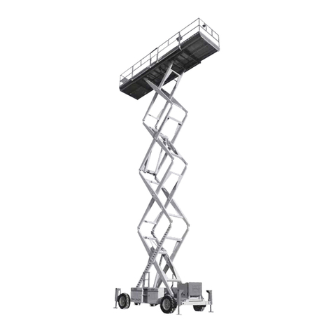
HANGCHA XEN Series User manual

Aerial Work Platform - All-electric Scissor Lift
OPERATION MANUAL
Model
65XEN
78XEN
80XEN
100XEN
120XEN
140XEN
160XEN
80XENS
100XENS
160XENS
HANGCHA GROUP CO., LTD.
5/2023
XEN Series

Preface
Thank you for purchasing and using our XEN-series Aerial Work Platform.
Please read, understand and abide by the safety rules and operation instructions stated in this
manual before any operations. Only fully-trained and authorized personnel should operate the
machine. This manual should be regarded as a part of the machine and always kept with it.
This manual provides instructions on how to use this aerial work platform properly and guidance on
the safe operation and preventive maintenance. It also describes the working principles and fault
diagnosis procedures for this machine. In order to ensure safety and make full use of the
performance of your machine, the operators and maintenance personnel concerned must read this
manual thoroughly before using it.
Some contents in this manual may be different from your product due to continuous design updates
and product improvements.
For any queries, please contact the sales company or agent of HANGCHA GROUP CO., LTD.

Contents
1 Instructions for use......................................................................................................................................1
1.1 Overview...................................................................................................................................................1
1.2 Operation rules.........................................................................................................................................1
1.3 Application environments........................................................................................................................1
1.4 Storage conditions....................................................................................................................................2
1.5 Obligations and responsibilities of the user ............................................................................................2
1.6 Installation of attachments or modification of the machine ..................................................................2
2. Introduction................................................................................................................................................4
2.1 Overview...................................................................................................................................................4
2.2 Functions...................................................................................................................................................5
2.3 Key parts ...................................................................................................................................................7
2.4 Display and control...................................................................................................................................8
2.5 Labels and signs......................................................................................................................................10
2.6 Main performance parameters ..............................................................................................................11
3 Safety rules.................................................................................................................................................16
3.1 Overview.................................................................................................................................................16
3.2 Instructions on signs...............................................................................................................................16
3.4 Risk of electrical shock ...........................................................................................................................18
3.5 Danger of rollover...................................................................................................................................18
3.6 Hazards in the work environment..........................................................................................................21
3.7 Danger of unsafe operation....................................................................................................................22
3.8 Danger of falling......................................................................................................................................23
3.9 Danger of collision..................................................................................................................................24
3.10 Danger of jamming ...............................................................................................................................25
3.11 Danger of explosion/fire ......................................................................................................................25
3.12 Danger of machine damage .................................................................................................................25
3.13 Danger of physical injury......................................................................................................................26
3.14 Battery hazards.....................................................................................................................................26
3.15 Hydraulic system hazards .....................................................................................................................27
3.16 Welding and grinding safety.................................................................................................................27
3.17 Lock after use........................................................................................................................................28
4. Lifting, fastening and towing....................................................................................................................29
4.1 Lifting ......................................................................................................................................................29
4.2 Fastening and fixing................................................................................................................................30
4.3 Tow..........................................................................................................................................................30
5 Checks before operation............................................................................................................................31
5.1 Check the machine .................................................................................................................................31
5.2 Checks before operation.........................................................................................................................32
6. Functional test before operation .............................................................................................................34
6.1 Test the ground controller......................................................................................................................34
6.2 Test the platform control handle............................................................................................................35
6.3 Test the safety function..........................................................................................................................36

7 Operation instructions...............................................................................................................................40
7.1 Emergency measures..............................................................................................................................40
7.2 Operate on the ground...........................................................................................................................40
7.3 Operate on the platform ........................................................................................................................41
7.4 Extend and retract the platform..............................................................................................................42
7.5 Maintenance arm....................................................................................................................................43
7.6 Batteryand charger..................................................................................................................................44
8. Maintenance.............................................................................................................................................45

1
1 Instructions for use
1.1 Overview
The all-electric scissor lift described in this manual is only suitable for lifting or lowering personnel or the
relevant operating tools and materials to the designated height.
Users must operate and maintain the all-electric scissor lift according to this manual. Do not use the
all-electric scissor lift for purposes not mentioned in this manual as it may cause personal injury or even
death, or cause damage to the lift and other property.
1.2 Operation rules
Before any operations,
★Ensure that you have understood and practiced the rules for safe operation of the machine in this
operation manual.
—— Avoid possible hazards.
—— Always perform a pre-operation check.
—— Always perform a functional test before use.
—— Check the workplace.
—— Use the machine only according to its design intent.
★ Read, understand and follow the manufacturer's instructions and safety rules, operation manuals and
machine labels.
★ Read, understand and abide by the user’s safety rules and workplace regulations.
★ Read, understand and comply with all applicable government regulations.
★ Ensure that you have been properly trained to operate the machine safely.
1.3 Application environments
★The ground should be solid and flat and free from any subsidence during operation.
★Ambient temperature should be - 20℃ to 40℃.
★Relative humidity should not be greater than 90% (at 20℃).
★Altitude should not be greater than 1,000m.

2
★The wind speed should not be greater than 12.5m/s.
★The power supply voltage fluctuation should be within ±10%.
1.4 Storage conditions
★The all-electric scissor lift should be stored in an environment free from rain, sunlight and corrosive
gases.
★During storage, the all-electric scissor lift should be retracted to the bottom and then placed on solid
ground to make it horizontal in all dimensions. If pneumatic tires are used, the wheels should be lifted
from the ground.
★Check, repair and maintain the platform according to the instruction manual before use after it has been
idle for a long time (more than one month).
1.5 Obligations and responsibilities of the user
In this manual, the User refers to any natural or legal person who directly uses or appoints another person
to use the all-electric scissor lift. In special cases such as leasing or renting, the User refers to the party
who assumes the specified operational obligations according to the terms of the contract between the
machine owner and the user.
The User must ensure that the all-electric scissor lift is used only for the specified purpose and that any
danger that may risk the life and health of the user or a third party is eliminated in a timely manner. In
addition, the User must strictly observe accident prevention regulations, other technical safety regulations,
and guidelines for the operation, maintenance and repair of the all-electric scissor lift. The User must
ensure that all operators read and fully understand the content in this manual.
Failure to comply with this manual will automatically void our warranty. We are also not responsible for
any damage or losses caused by the user and/or third parties who perform unauthorized operations on
the all-electric scissor lift without our permission.
1.6 Installation of attachments or modification of the machine
No private modification of the all-electric scissor lift is allowed without the authorization of the
manufacturer.
If it is necessary to install or add additional devices that affect or add new functions to the machine, prior

3
written consent must be obtained from the manufacturer. Depending on the actual situation, the approval
and consent of the local authorities may also be required.
Any modification or refit of the vehicle that affects its performance, such as the rated capacity, stability, or
safety, is not permitted without prior written approval of the original manufacturer, its authorized
representative, or its successor. The aforementioned modifications include modifications or refit of the
platform, scissors, frame, side door, braking, steering, visibility, and the addition of removable
attachments. When the manufacturer or its successor approves any modifications to the all-electric scissor
lift, its nameplate, signs/labels and user’s manual should also be modified accordingly.
Only if the original manufacturer is no longer in the this industry and no other enterprise has taken over
the business, is the user is allowed to make modifications to the machine, but the user should comply with
the following rules:
★Entrust engineers specialized in industrial vehicle safety for the design, test and execution of the vehicle
modification or refit.
★Keep a permanent record of the design, test and execution of the vehicle modification or refit.
★Modify its nameplate, signs/labels and user’s manual accordingly.
★Fix a permanent and visible sign on the all-electric scissor lift, which states that it has been modified or
refitted and indicates the date of modification or refit and the name & address of the organization that
completed the work.

4
2. Introduction
2.1 Overview
This manual introduces the XEN-series aerial work platform and the user can determine the lifting height
and other information from the product model.
Model
Meaning
140
Lifting height × 100mm
X
Scissor type
E
Electric
N
New series
S
Slim body

5
2.2 Functions
Vehicle structure
★A serialization packaging design is adopted for the frame which features good water and dust resistance,
with tie-down points for transportation, so it is easy to load, unload and transport. The left- and right-side
doors can be opened by rotation for easy installation of the components of the hydraulic system and
electrical system and after-sale maintenance.
A double scissor structure is adopted and features high stability, minimal swaying, safe and stable
lifting/lowering action. Rubber gaskets are mounted between the square tubes, which act as buffers
during lowering and prevent hands from being jammed to protect personnel. The maintenance arm is
provided to facilitate maintenance in case of any faults.
★A folding design is adopted for the work platform and the height of the machine is reduced after the
platform is folded for ease of maneuvering. With a one-way extension function, the maximum extension
length of the platform is 0.9m to assist reaching the work area and increasing the operation scope. The
platform base is made of tread plates which are anti-skid and durable.
Main configuration
★The components of the hydraulic system have stable and reliable performance, and are sourced from
high-end brands to ensure consistent and smooth working performance. A emergency lowering device is
provided, so that in the event of any faults in the electrical system, manual lowering can be performed; a
braking release device is also provided, so when the machine is stuck due to a fault, the operator can
release the brake manually to drive the machine.
★The electrical system adopts the most common control system in used this industry, and the ground
control panel and the platform control handle are equipped with separate emergency stop switches, thus,
in case of an emergency, all actions can be immediately stopped by pressing the emergency switch button,
to ensure the safety of operators. The control handle integrates the traveling, lifting and steering control
functions, and can be operated by one hand. Proportional control is adopted to reduce the impact of
movement and ensure a steady and smooth operation. The ground control panel is equipped with a timer
to display the running time of the machine. The chassis is equipped with a display screen to display the
electrical fault codes for the ease of fault diagnosis. The machine is equipped with a charger to facilitate
charging the battery and an all-action warning system which will give a sound-light alarm from the buzzer

6
and strobe light when any action is performed.
★Different types of batteries can be specified for the machine, including a lead-acid battery, traction
battery and lithium-ion battery, the traction battery has a large capacity and long service life, while the
charging time of the lithium-ion battery is shorter, with a high efficiency.
Safety devices
★2-m stop device: When the platform is lowered to a height of 2 meters, the lowering action will be
paused. If the operator wants to restart the lowering process, he/she should re-press the lowering button
and the platform will be lowered again after a 3s delay, to avoid any danger to people on the ground.
★Anti-rollover protection device: It opens automatically when the platform is lifted to ensure that the
machine will not roll over when the machine is driven over a pothole.
★Hydraulic cylinder anti-burst device: It is used to prevent the hydraulic pipe from bursting and
automatically lowers the platform to ensure the personnel safety.
★Tilt alarm device: When the machine tilts beyond the setting range, the buzzer will emit an urgent alarm
sound, and the platform cannot be lifted.
★Overload alarm device: When the values detected by the height sensor and pressure sensor exceed the
curve setting values, the platform cannot be lifted and the buzzer will sound an alarm.
★Charge protection system: When charging the battery, the system will automatically cut off the whole
circuit to ensure electrical safety.

7
2.3 Key parts
1. Access door
2. Brake pedal
3. Control handle
4. File case
5. Extensible platform
6. Safety belt anchorage
7. Fixed platform
8. Scissor arms
9. Chassis
10. Steering assembly
11. Tires
12. Battery
13. Power-off switch
14. Charger
15. Anti-rollover device
16. Emergency lowering
handle
17. Step board
18. Brake release valve
19. Maintenance arm
20. Warning light
21. Control module
22. Chassis control panel
23. Limit switch
24. Level sensor
25. Inching switch

8
2.4 Display and control
1、ECU Display screen: It is used to display machine modes or
fault codes.
2、Parameter setting: It is used to set/change the system
parameters.
3. Ground lifting/lowering control: It is used to control the
lifting and lowering action of the platform on the ground.
4. Emergency stop switch: It is used to stop all functional
actions.
5. Key switch: It is used to switch between the ground and
platform control.
6. Enable button: It is used to enable the driving/lifting
function.
7. Steering button: It is used to control the machine to turn
left or right
8. Control handle: It is used to control the lifting, lowering,
forward and backward action of the machine.
1
3
4
5
6
2
7
8
9
10
11
12
13

9
9. Driving button: The driving function is activated when the indicator light turns on.
10. Lifting button: The lifting function is activated when the indicator light turns on.
11. Speed button: The low speed mode is activated when the indicator light turns on.
12. Horn button: It is used to sound the horn.
13. PCU Display screen: It is used to display the current battery level or fault codes.

10
320Kg=160Kg +
705Lbs=353Lbs+ 2
400N(40Kg-90Lbs)
113Kg=33Kg +
249Lbs=73Lbs+ 1
平台共设有四个锚点,每个锚点限一人使用
There are four safety hooks ,
Each hook restraint one person.
320Kg=160Kg +
705Lbs=353Lbs+ 2
400N(40Kg-90Lbs)
挤压危险
与活动的剪刀叉接触可
能导致死亡或严重受伤
在进行维护或修理前,请使用安全臂;
只有平台空载情况下允许使用安全臂。
Engage safety arm before performing
maintenance or repair.
Do not engage safetyarm unless
unload plaform.
Crushing Haza rd
Dead or serious injury
can result from contact
with moving scissor arms
轮胎载荷
020002
2.5 Labels and signs
The labels and warning signs, such as the product nameplate, load curve sign and warning labels, must be
clear and visible. If not, they should be replaced. The following figure shows the approximate positions for
various labels and signs. Please become familiar with the labels and signs before operating the machine.
1. Safety belt anchorage label
2. Rated load capacity label
3. Safety belt hook label
4. Manufacturer label
5. Vehicle model label
6. Mind your head label
7. Danger of trapping label
8. Maintenance instruction label
9. Tire load capacity label
10. Tire replacement warning label
11. Battery safety warning label
12. Battery replacement warning label
13. Power-off instruction label
14. Foot trap warning label
15. Warning line label
16. Tie-down point for lifting label
17. Emergency lowering instruction label
18. Brake release instruction label
19. Platform safe load label
20. Waterproof label
21. Pre-operation caution label
22. Manufacturer label
23. IPAF label
24. CE label
25. Product nameplate

11
2.6 Main performance parameters
The technical data given below lists the parameters of machine in standard configuration. Our company
reserves the right to make changes and additions to the technical data.
Parameter
Unit
65XEN
78XEN
Dimensions
Length
m
1.89
1.89
Width
m
0.81
0.81
Height (folded
guardrail)
m
1.66
1.77
Height (unfolded
guardrail)
m
2.10
2.21
Ground clearance
m
0.077
0.077
Ground clearance (with enabled
anti-rollover device)
m
0.016
0.016
Total weight
kg
1315
1435
Working size
Max. platform height
m
4.50
5.80
Max. working height
m
6.50
7.80
Max. horizontal length
m
0.90
0.90
Safe working load
kg
320
230
Safe load for extended platform
kg
113
113
Max. working staff
Numbe
r of
people
Indoors - 2 /
Outdoors - 1
Indoors - 2 /
Outdoors - 1
Wheelbase
m
1.365
1.365
Wheelbase
m
0.71
0.71
Turning radius
Inner wheel
m
0
0
Outer wheel
m
1.64
1.64
Max allowable lateral force
N
400N
400N
Control voltage (DC)
V
24
24
Platform size
Length
m
1.67
1.67
Width
m
0.76
0.76
Tire size
Diameter
mm
305
305
Width
mm
100
100
Hydraulic system pressure
MPa
24
24
System voltage (DC)
V
24
24
Vehicle speed
Retracted state
km/h
3.5
3.5
Extended state
km/h
0.8
0.8
Gradeability
%
25
25
Max allowable wind speed
m/s
12.5
12.5
Max allowable tilt
angle
Front/Rear
°
3
3
Left/Right
°
1.5
1.5

12
Parameter
Unit
80XENS
100XENS
Dimensions
Length
m
2.48
2.48
Width
m
0.81
0.81
Height (folded
guardrail)
m
1.79
1.93
Height (unfolded
guardrail)
m
2.23
2.32
Ground clearance
mm
100
100
Ground clearance (with enabled
anti-rollover device)
mm
20
20
Total weight
kg
2085
2180
Working size
Max. platform height
m
6.00
8.00
Max. working height
m
8.00
10.00
Max. horizontal length
m
0.90
0.90
Safe working load
kg
380
230
Safe load for extended platform
kg
113
113
Max. working staff
Numbe
r of
people
Indoors only - 2
Indoors only - 2
Wheelbase
m
1.86
1.86
Wheel track
m
0.71
0.71
Turning radius
Inner wheel
m
0
0
Outer wheel
m
2.1
2.1
Max allowable lateral force
N
400N
400N
Control voltage (DC)
V
24
24
Platform size
Length
m
2.27
2.27
Width
m
0.76
0.76
Tire size
Diameter
mm
381
381
Width
mm
127
127
Hydraulic system pressure
MPa
24
24
System voltage (DC)
V
24
24
Vehicle speed
Retracted state
km/h
3.5
3.5
Extended state
km/h
0.8
0.8
Gradeability
%
25
25
Max allowable wind speed
m/s
0
0
Max allowable tilt
angle
Front/Rear
°
3
3
Left/Right
°
1.5
1.5

13
Parameter
Unit
80XEN
100XEN
Dimensions
Length
m
2.48
2.48
Width
m
1.15
1.15
Height (folded
guardrail)
m
1.65
1.77
Height (unfolded
guardrail)
m
2.23
2.37
Ground clearance
mm
100
100
Ground clearance (with enabled
anti-rollover device)
mm
20
20
Total weight
kg
2230
2370
Working size
Max. platform height
m
6.00
8.00
Max. working height
m
8.00
10.00
Max. horizontal length
m
0.9
0.9
Safe working load
kg
450
450
Safe load for extended platform
kg
113
113
Max. working staff
Numbe
r of
people
2
2
Wheelbase
m
1.86
1.86
Wheel track
m
1.02
1.02
Turning radius
Inner wheel
m
0
0
Outer wheel
m
2.2
2.2
Max allowable lateral force
N
400
400
Control voltage (DC)
V
24
24
Platform size
Length
m
2.27
2.27
Width
m
1.14
1.14
Tire size
Diameter
mm
381
381
Width
mm
127
127
Hydraulic system pressure
MPa
24
24
System voltage (DC)
V
24
24
Vehicle speed
Retracted state
km/h
3.5
3.5
Extended state
km/h
0.8
0.8
Gradeability
%
25
25
Max allowable wind speed
m/s
12.5
12.5
Max allowable tilt
angle
Front/Rear
°
3
3
Left/Right
°
1.5
1.5

14
Parameter
Unit
120XEN
140XEN
Dimensions
Length
m
2.48
2.48
Width
m
1.15
1.15
Height (folded
guardrail)
m
1.91
2.05
Height (unfolded
guardrail)
m
2.50
2.65
Ground clearance
mm
100
100
Ground clearance (with enabled
anti-rollover device)
mm
20
20
Total weight
kg
2810
3040
Working size
Max. platform height
m
10.00
11.80
Max. working height
m
12.00
13.80
Max. horizontal length
m
0.90
0.90
Safe working load
kg
320
320
Safe load for extended platform
kg
113
113
Max. working staff
Numbe
r of
people
Indoors - 2 /
Outdoors - 1
Indoors only - 2
Wheelbase
m
1.86
1.86
Wheel track
m
1.02
1.02
Turning radius
Inner wheel
m
0
0
Outer wheel
m
2.2
2.2
Max allowable lateral force
N
400
400
Control voltage (DC)
V
24
24
Platform size
Length
m
2.27
2.27
Width
m
1.14
1.14
Tire size
Diameter
mm
381
381
Width
mm
127
127
Hydraulic system pressure
MPa
24
24
System voltage (DC)
V
24
24
Vehicle speed
Retracted state
km/h
3.5
3.5
Extended state
km/h
0.8
0.8
Gradeability
%
25
25
Max allowable wind speed
m/s
12.5
0
Max allowable tilt
angle
Front/Rear
°
3
3
Left/Right
°
1.5
1.5

15
Parameter
Unit
160XEN
160XENS
Dimensions
Length
m
2.84
2.84
Width
m
1.4
1.25
Height (folded
guardrail)
m
2.04
2.04
Height (unfolded
guardrail)
m
2.64
2.64
Ground clearance
mm
100
100
Ground clearance (with enabled
anti-rollover device)
mm
20
20
Total weight
kg
3240
3280
Working size
Max. platform height
m
13.7
13.7
Max. working height
m
15.7
15.7
Max. horizontal length
m
0.90
0.90
Safe working load
kg
230
230
Safe load for extended platform
kg
113
113
Max. working staff
Numbe
r of
people
Indoors only - 2
Indoors only - 2
Wheelbase
m
2.23
2.23
Wheel track
m
1.27
1.12
Turning radius
Inner wheel
m
0
0
Outer wheel
m
2.70
2.65
Max allowable lateral force
N
400
400
Control voltage (DC)
V
24
24
Platform size
Length
m
2.64
2.64
Width
m
1.14
1.14
Tire size
Diameter
mm
381
381
Width
mm
127
127
Hydraulic system pressure
MPa
24
24
System voltage (DC)
V
24
24
Vehicle speed
km/h
km/h
3
3
km/h
km/h
0.8
0.8
Gradeability
%
25
25
Max allowable wind speed
m/s
0
0
Max allowable tilt
angle
Front/Rear
°
3
3
Left/Right
°
1.5
1.5

16
3 Safety rules
Failure to follow the instructions and safety rules in this manual may result in death or serious
injury.
3.1 Overview
Whether you are the owner, user or operator of the machine, before operating it for
the first time, you must read through and thoroughly and properly understand the
contents of this manual, and operate the machine according to the operation
procedures under the supervision of qualified personnel with practical operating
experience before operating it independently. If you have any questions about the
use or operation of the machine, please promptly call the HANGCHA GROUP CO., LTD.
for consultation.
Most of the accidents that occur during the operation, maintenance and repair
process are caused by the failure to follow the basic safety operation procedures and
precautions. If the potential safety hazards are analyzed and corresponding safety
measures taken before operation, most accidents can be completely avoided.
Therefore, before operation, an evaluation should be made by a safety officer who is
trained with the ability to analyze the potential safety hazards and remind the
operator to take the necessary countermeasures to avoid them.
3.2 Instructions on signs
The meanings of the symbols, color codes and text used in the
product labels of Hangcha Group Co., Ltd. are described as follows:
This safety warning sign is contained in most safety statements. It
means that precautions should be taken at all times otherwise your
safety will be at risk. Read and follow the information contained in the safety warning
signs.
This manual suits for next models
10
Table of contents
Popular Lifting System manuals by other brands

Nova Technology International, LLC
Nova Technology International, LLC Standard Profile Truck Lock Series Owner & user manual

Pride Mobility
Pride Mobility Zeus 260/440lb Fitting instructions
Audipack
Audipack PCL-X355 manual

Tonka
Tonka Lift TL7000 instructions
Snorkel
Snorkel TB66J Repair parts manual

human care
human care FL180 Quick reference guide
RocwooD
RocwooD RWFSR180 IM instruction manual
Dhollandia
Dhollandia DH-V Series Operation manual

Big Lift
Big Lift CB22-128 Operation, maintenance, repair parts list

LIFTINGITALIA
LIFTINGITALIA DomoFlex MM13 Mounting, installation and diagnostics
probst
probst WEZ-2 operating instructions

Denka Lift
Denka Lift DL25 instruction manual
