Hangzhou Ruideng Technology RD6006-W User manual
恒压恒流数控电源操作手册
型号:RD6006-W/ RD6012-W/ RD6018-W/ RD6024-W /RD6006P-W /RD6012P-W
此处设计纸质说明书封面
汇总意见投票 支持打钩,意见可以在下面手写
1页眉去掉
2. 缩减行间距
3.增加目录
4.增加产品购买链接
5.增加视频说明链接
- 1 -
恒压恒流数控电源操作手册
型号:RD6006-W/ RD6012-W/ RD6018-W/ RD6024-W /RD6006P-W /RD6012P-W
修订时间:2022.9.9
尊敬的用户,感 谢您购买由杭州睿登科技有限公司出品的恒压恒流数控电源,为了让您更快了
解本产品的全部功能,获得更好的使用体验,避免出现误操作,使用前请仔细阅读本说明并保留好,
以便日后查阅。本手册只有操作说明,APP 以及上位机说明请访问:
http://www.ruidengkeji.com/ziliaoxiazai/
本说明书对应固件版本 RD6006-V1.38,RD6012-V1.38,RD6018-V1.38,
RD6024-V1.37,RD6006P-V1.41,RD6012P-V1.44 ,不同固件版本下,界面或
操作可能会有不同,使用时请注意。建议升级为最新固件,获取更好的使用
体验。
2
1.1 配件清单
RD 数控电源主机一台
X25A 输出线一套
220V 输入线一条
Micro 通信线一条(X25A 包装内)
外置温度传感器一条 10KB3950
备用保险丝一只(这里把字 p掉)
1.2 产品技术指标
产品型号
RD6006-W
RD6012-W
RD6018-W
RD6024-W
RD6006P-W
RD6012P-W
输入电压范围
6-70V
7-70V
电压电流位数
四位
五位
输出电压范围
0-60V
输出电流范围
0-6A
0-12A
0-18A
0-24A
0-6A
0-12A
输出功率范围
0-360W
0-720W
0-1080W
0-1140W
0-360W
0-720W
电压分辨率
0.01V
0.001V
电压精度
±(0.3%+3 个字)
±(0.5‰+4 个字)①
电流分辨率
0.001A
0.01A
0.0001A
0.0001A
/0.001A
电流精度
±(0.5%+5 个字)
±(1‰+6 个字)
输入电压分辨率
0.01V
输入电压精度
±(1%+5 个字)
电池电压分辨率
0.01V
电池电压精度
±( 0.5%+3个字)
默认充电关闭电流
10mA
100mA
10mA
10mA
输出纹波典型值
(VPP)
100mV
250mV@6A
100mV
@12A
150mV
@24A
20mV②
产品型号
RD6006-W
RD6012-W
RD6018-W
RD6024-W
RD6006P-W
RD6012P-W
产品工作温度范围
-10℃~40℃
外置温度传感器测量范围
-10℃~100℃/0℉~200℉
3
外置温度传感器测量误差
±3℃/±6℉
恒压模式响应时间
2ms(0.1A-5A 负载)
恒压模式负载调整率
±(0.1%+2个字)
恒流模式负载调整率
±(0.1%+3个字)
容量测量范围
0-9999.99Ah
能量测量范围
0-9999.99Wh
容量能量记录误差
±2%
最大输出电压
(输入电压÷1.1)-1
(输入电压÷1.1)-2③
散热风扇开启
输出电压>
40V 或输出
电流>4A 或
系统温度
>45℃
输出电流>8A 或
系统温度>45℃
输出电流>4A 或
系统温度>50℃
散热风扇开启后关闭
输出电压<
40V 且输出
电流<3.9A
且系统温度
<45℃
输出电流<7.9A 且
系统温度<45℃
输出电流<3.9A 且
系统温度<50℃
过温保护
系统温度>80℃
屏幕亮度设置
0-5 共6级
显示屏幕
2.4 寸彩色液晶显示屏
产品净重(约)
3.3 kg
3.8 kg
3.9 kg
4.1 kg
3.4 kg
3. kg
产品尺寸(约)
17.3*9.2*33.6 cm
USB 通信
支持
WiFi 通信
支持
①:精度计算方法:一个字为一个最小分辨率,5V 下误差为±(5*0.5‰+4*0.001) ,5±0.0065V
②:纹波测量方法:测量输出接线端子处,并联 0.1uF 电容,示波器 X1 档,交流耦合,20MHz
限制,使用纯电阻负载。
③:例,输入电压为 24V,此时最大输出电压为 20.8V。
下面以 RD6012P-W 为例介绍外观和使用说明。
1.3 面板说明
1.3.1 前面板
4
A:电源开关
B:SHIFT 第二功能键
C:快捷存储键
D:输出电流/过流保护设置
E:输出电压/过压保护设置
F:micro USB 通信接口
G:电源输出负极/电池充电负极
H:电池充电正极(充电专用端子)
I:电源输出正极
J:输出开关键
K:ENTER/确认键
L:编码电位器(旋转)/返回键(按动)
M:方向键
N:数字键盘
O:显示屏幕 0
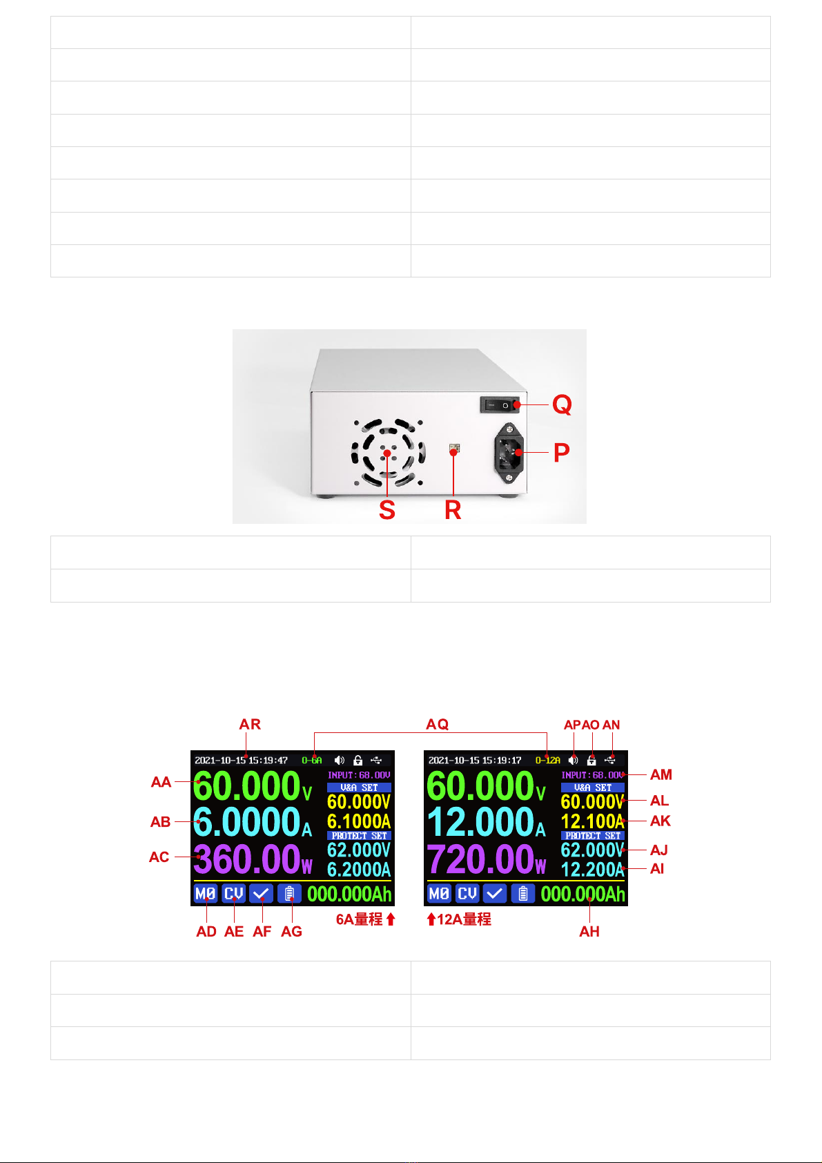
1.3.2 后面板
P:输入电源接口
Q:开关
R:外置温度传感器接口
S:散热孔
1.4 操作说明
上电后首先显示开机图片,然后进入主界面。
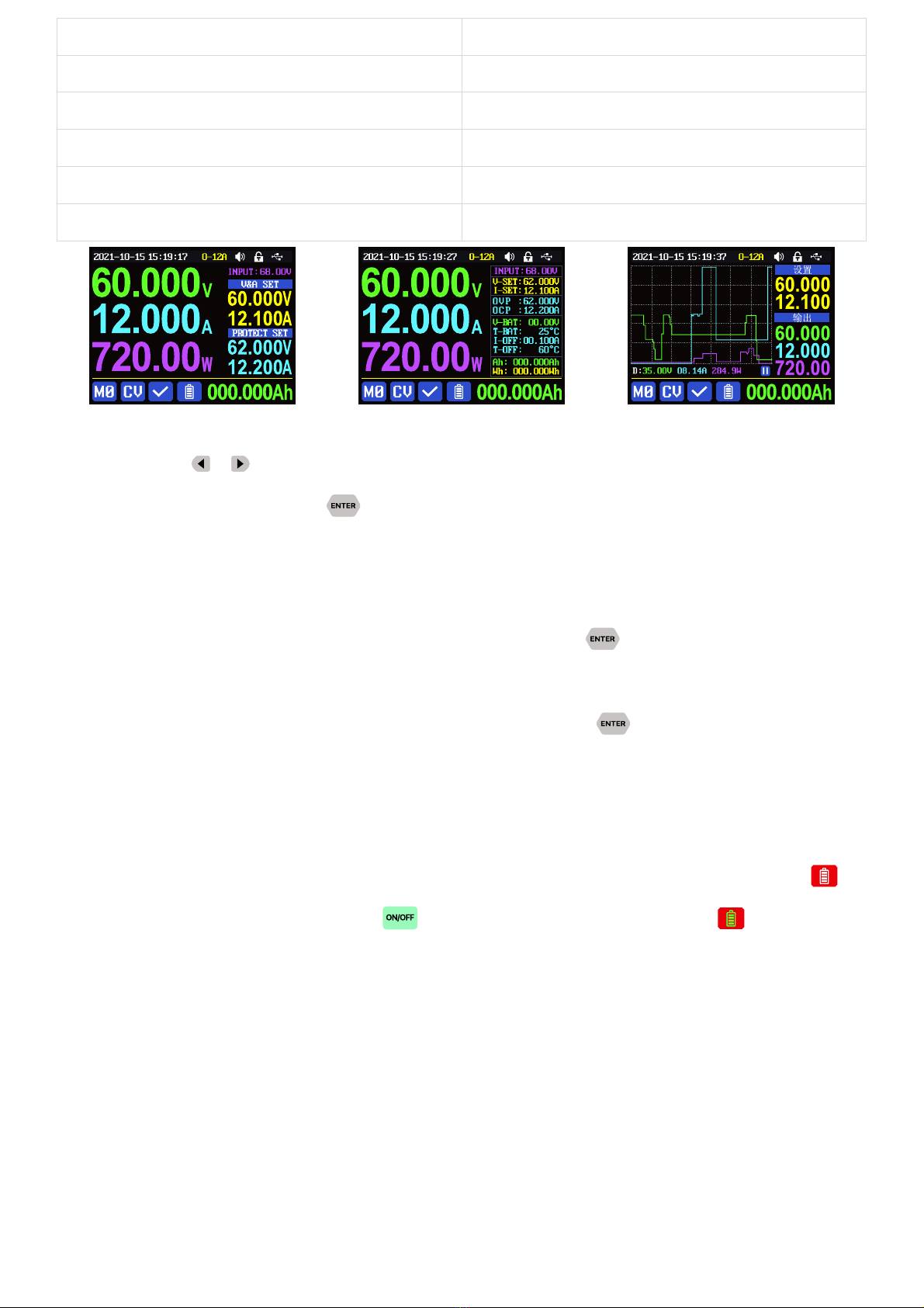
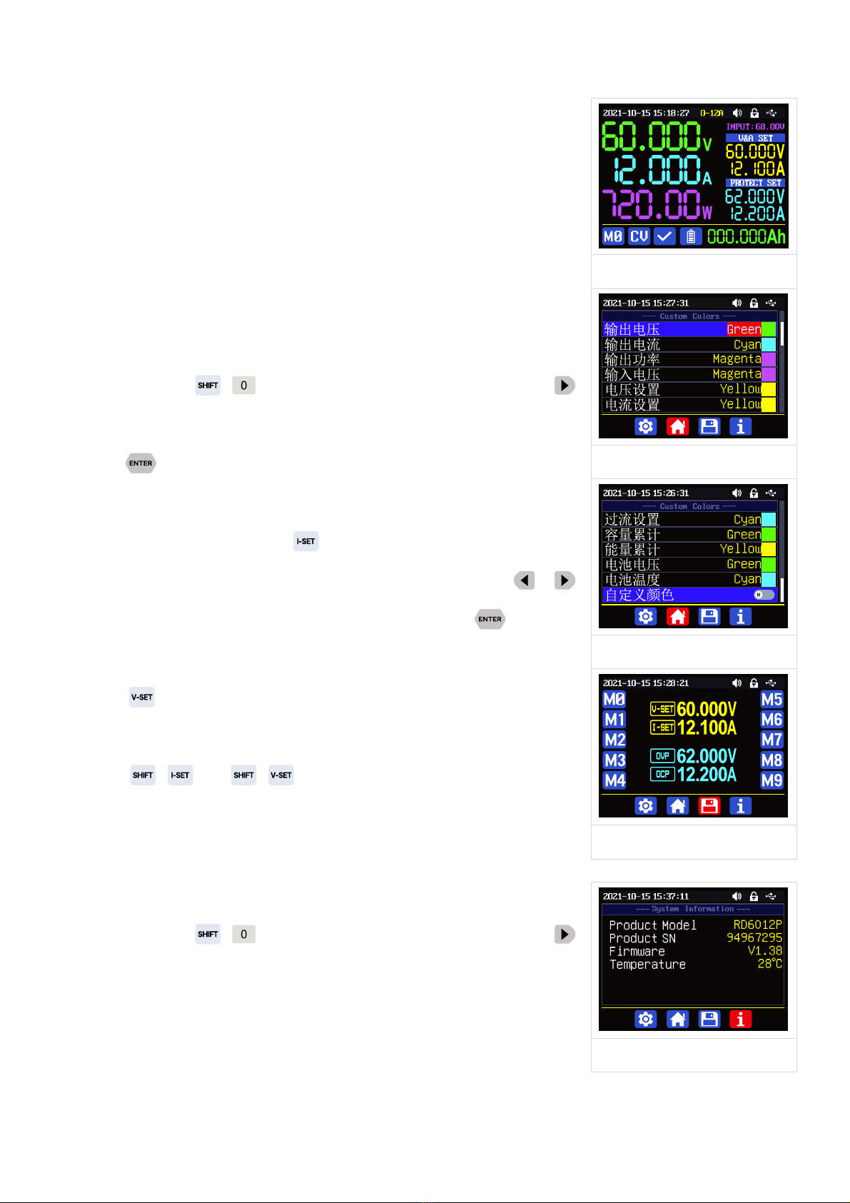
1.4.1 主界面
AA:输出电压回读值
AB:输出电流回读值
AC:输出功率显示值
AD:当前数据组指示
AE:恒压恒流状态指示
AF:保护状态指示
5
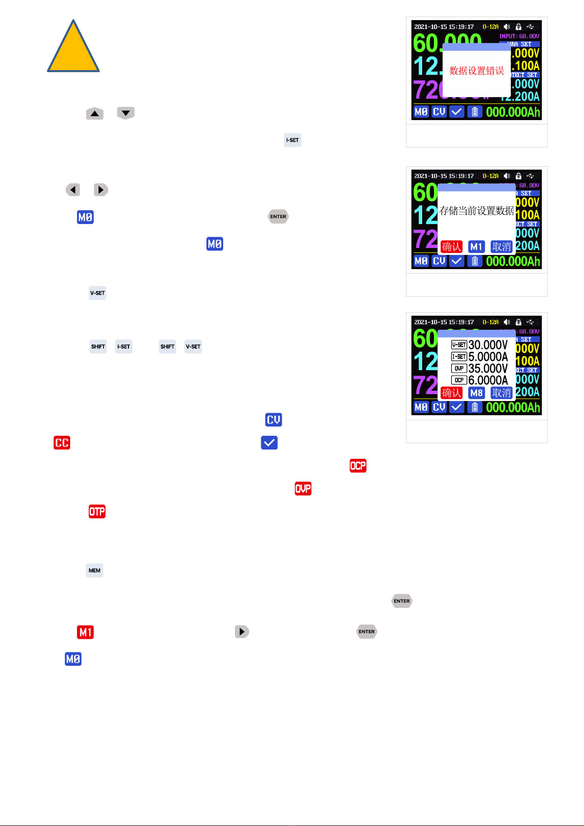
经典风格
详细风格
曲线风格
主界面按动 或 键可以在经典风格、详细风格、曲线风格中切换,曲线风格下,旋转编码电
位器可以缩放曲线纵坐标,按动 键可以开始或暂停曲线显示;主界面调整风格状态后不记忆,
如需设置默认启动界面风格请前往 1.4.2.6 主界面风格设置。
1.4.2 操作说明
菜单操作中,红色、光标处或反显处为当前选中菜单,按动 键确认或进入,按动编码电位
器返回,按动方向键移动光标或菜单翻页,旋转编码电位器更改设置,菜单中返回时自动保存设置。
按住 0键上电恢复出厂设置,按住 1键上电恢复出厂校准值,按住 键上电进入 boot 模式。
1.4.2.1 电池充电功能说明
上电后,循环显示区处,外置温度传感器温度、容量、能量循环切换显示,电源输出时,容量、
能量自动累计,关机清零。
电池充电正极接电池正极,电源输出负极接电池负极,正确连接电池后电池充电状态指示 提
示电池接好,设定好电压电流后然后按 键开始充电,同时电池充电状态指示 提示,当输出
电流小于充电截止电流(100mA 可设定)或外置温度传感器测量温度大于充电截止温度时自动关闭
输出。当使用带异口保护板的电池需要使用电源输出正极和电源输出负极充电,电池充电时的电压
电流需要自行设定。
AG:电池充电状态指示
AH:循环显示区
AI:输出过流保护设定值
AJ:输出过压保护设定值
AK:输出电流设定值
AL:输出电压设定值
AM:输入电压
AN:当前通信模式指示
AO:按键状态指示
AP:按键声音状态指示
AQ:电流量程指示(仅 RD6012P 有此选项)
AR: 日期时间
6
强烈建议使用原装充电器给电池充电,本机充电功能仅
能起临时替代作用,只有详细了解电池参数才可以充电,
错误设置会损害电池寿命甚至起火爆炸。
1.4.2.2 主界面电压电流设置
按动 或 键可以在 6A、12A 两个电流量程指示中切换(仅限
RD6012P-W),切换量程时会自动关闭输出。按动 键设定输出电流设
定值,转动编码电位器时设定值立刻生效,旋转调整不会超过限制,
按动 或键可以更改光标位置,待按动编码电位器返回时,自动
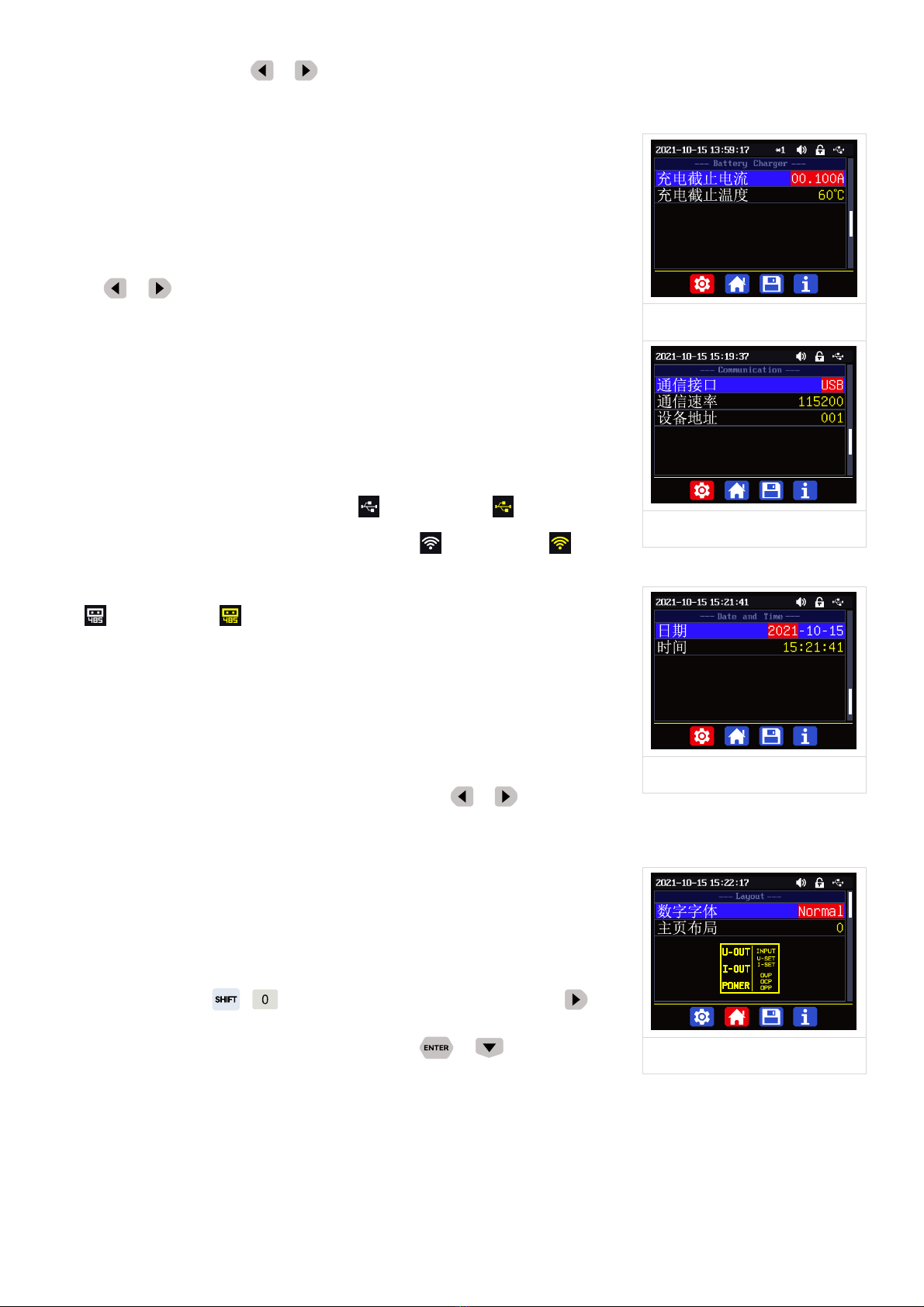
保存到 。也可以直接使用数字键盘输入按 键确认后设定值生效
同时自动将量程和设定值保存到 。如果设定值超过限制,弹窗提示
数据设置错误(如图一)。如输入错误,可以按动编码电位器取消。
按动 键可以设定输出电压设定值,方法类似输出电流设定值操
作。
先按 +键或 +键可以设定输出过流保护设定值或输
出过压保护设定值,方法类似输出电流设定值操作。如果需要过流关
断功能,输出过流保护设定值应小于输出电流设定值。
电源处于恒压状态下恒压恒流状态指示 提示,当处于恒流状态
下 提示;电源正常状态下保护状态指示 提示,当输出电流回读
值大于输出过流保护设定值(OCP)后,电源自动关闭输出,并 提示,当输出电压回读值大于输出
过压保护设定值(OVP)后,电源自动关闭输出,并 提示,当系统温度大于 80℃,电源自动关闭
输出,并 提示。
1.4.2.3 快捷存储和调出
按动 +数字键盘 1-9,可以将当前输出电压设定值、输出电流设定值、输出过压保护设定值、
输出过流保护设定值、电流量程指示存储为快捷调用(如图二),按动 键确认,左下角当前数据
组指示 提示,按动编码电位器或按 键选中“取消”后按 键取消,再次手动改变设置值后
变为 提示。
图一
图二
图三

7
按动 +数字键盘 1-9 可以快捷调出存储的数值(如图三)按动
键确认后输出电压设定值、输出电流设定值、输出过压保护设定
值、输出过流保护设定值、电流量程指示修改,左下角当前数据组指
示提示,再次手动改变设置值后变为 提示。在系统设置菜单中关
闭调出确认后,不弹出窗口,直接修改设置值。
为上电默认数据组,按键修改设定后按 键或旋转编码电位
器更改设定后按编码电位器返回后自动记忆至数据组 ,或在存储数
据中修改后按编码电位器返回后记忆,其他操作不记忆。
1.4.2.4 键盘锁定解锁
按动 +键可以锁定或者解锁键盘。键盘锁定时按键状态指示
提示,此时电源开关可正常使用,按动其他按键提示错误(如图四)。
通信时自动锁定键盘 (不可手动解锁),通信断开 3秒以后自动解锁键
盘,按键状态指示 提示。
1.4.2.5 系统设置
主界面下按动 +键进入系统设置菜单,最下面红色显示图标
为主菜单选中位置,按动 或 键进入子菜单,蓝色底色为子菜单
选中位置,旋转编码电位器改变设置,按动编码电位器返回,此时按
动 或 键可以切换主菜单。
按动 +键进入如图四系统设置主菜单,按动 或 键进入子菜单。
Settings 子菜单:(如图五)
系统语言默认为英文,也可以简体中文、法语、德语、俄语中选择;
调出确认默认打开,快捷调出时会先弹出窗口,关闭后快捷调出时直接更改设置值;
调出输出默认关闭,快捷调出时关闭输出,打开后,快捷调出后自动打开输出;
开机输出默认关闭,开机时输出为关闭,打开后开机自动打开输出;
开机图片默认打开,开机后会首先加载开机图片,然后进入主界面,关闭后开机直接进入主界面;
按键声音默认打开,按键声音状态指示 提示,按动按键会有短促的滴滴声,关闭后,按键声音
状态指示 提示,按键静音;
背光亮度默认为 4,可以在 0-5 之间设置;
测量速度默认为低,可以设置低中高三档,对应的是输出电压电流实际值的刷新率;
图四
图五
图六
8
最大功率默认为 740W,可以在 0-740W 之间设置,对应可以设置的最大功率,右上角图标*1 为调
整倍率,可以通过按动 或 键实现不同倍率调整,快速设置需要的数值,最大功率默认为电压
优先模式,当设定电压电流乘积超过最大功率,系统自动将输出电流设定值减小,可以匹配小功率
前级电源时使用,推荐设置值为前级电源的额定功率*95%;
温度单位默认为℃,可以在℃和℉之间切换。(如图六)
Battery Charger 子菜单:(如图七)
充电截止电流默认 100mA 可调,右上角图标*1 为调整倍率,可以通过
按动 或键实现不同倍率调整,快速设置需要的数值,充电时输
出电流回读值小于此数值后自动关闭输出;
充电截止温度默认为 60℃,充电时当外置温度传感器测量温度大于 60℃
后自动关闭输出。
Communication 子菜单:(如图八)
通信接口默认为 USB,也可以在 WIFI、TTL、RS485 中切换,USB 指micro
USB 接口,设置后当前通信模式指示 提示,通信时 提示;WIFI 需
要插接 WiFi 模块,设置后当前通信模式指示 提示,通信时 提示;
TTL 功能暂未开放,RS485 需要插接 485 模块,设置后当前通信模式指
示提示,通信时 提示;
设备地址默认为 001,可以在 001-255 之间选择;通信速率和设备地址
必须和上位机和手机 APP 保持一致。通信功能具体详见完整版说明书
中上位机和 APP 中连机部分。
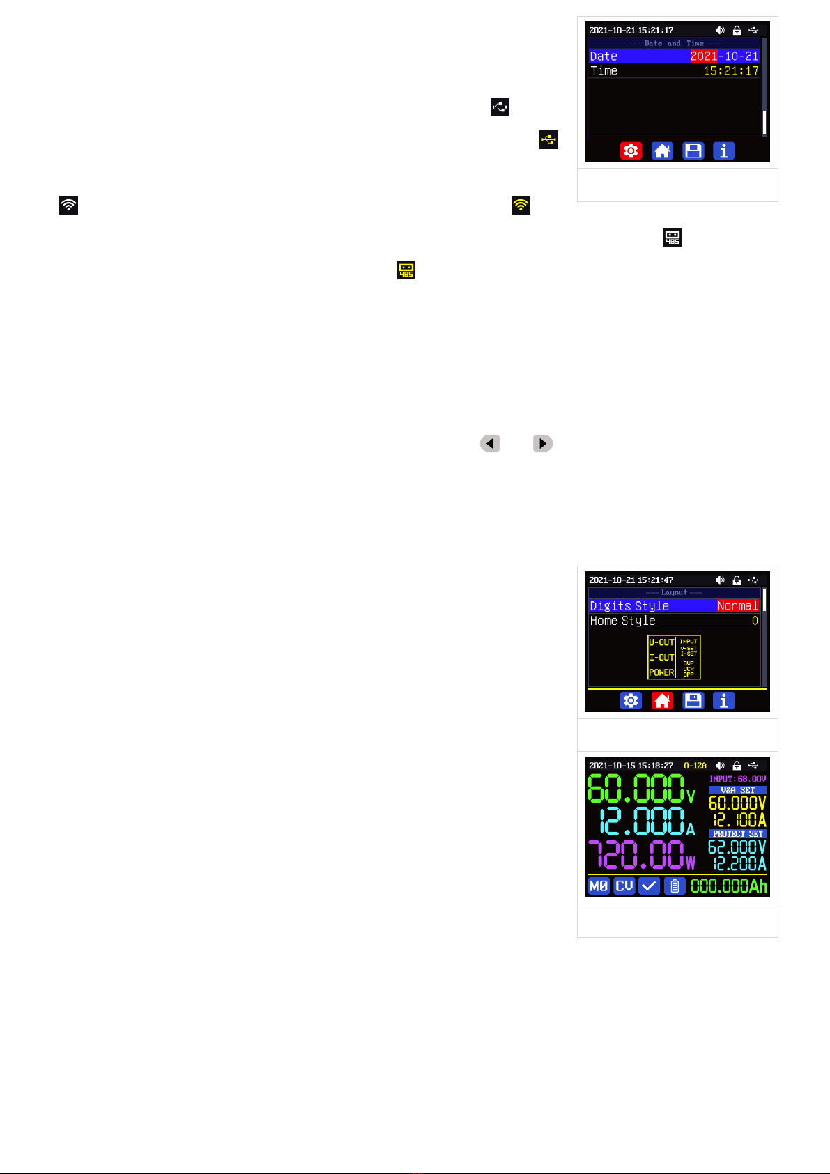
Date and Time 子菜单:(如图九)
日期和时间可以在 2000-2100 年之间设置,按动 或 键,更改设置
选项,旋转编码电位器改变数值,改变后立即保存更改,请不要设置错误的日期。使用 PC 上位机
和手机 APP 可以手动更小时间,详见完整版说明书中上位机和 APP 中
连机部分。
1.4.2.6 主界面风格设置
主界面下按动 +键进入系统设置菜单,然后再按动 键进
入(如图十)主界面风格设置主菜单下:按动 或 键进入菜单
Layout 子菜单:
数字字体默认为 Normal,可以在 Normal 和7-Seg V1 和7-Seg V2 中选择;7-Seg V2 显示效果(如
图十一)
图七
图八
图九
图十
9
主页布局默认为 0经典风格,可以在 0经典风格、1详细风格,2图表风格三个风格中选择,此处
设定为开机默认界面风格。
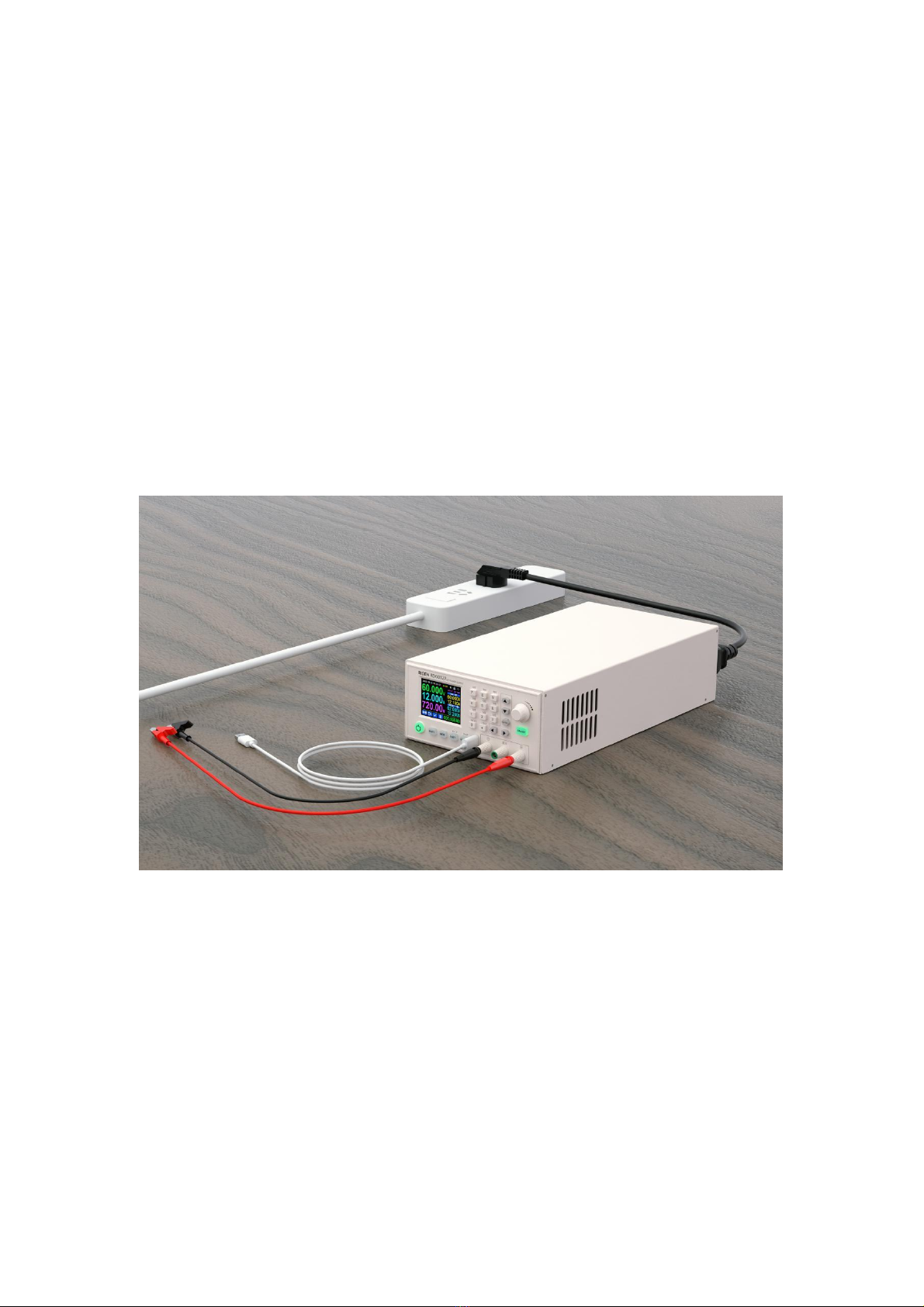
Custom Colors 子菜单:(如图十二)
输出电压、输出电流、输出功率、输入电压、电压设置、电流设置、
过压设置、过流设置、容量累计、能量累计、电池电压、电池温度中
每个独立的项目可以设置单独的颜色,颜色可以在红、绿、蓝、白、
黄、品红、青色、浅蓝、灰色、棕色、橙色、黄绿色、蓝绿色、粉色、
栗色十五个颜色中选择,改变设置后,打开自定义颜色,就可以开启(如
图十三)。
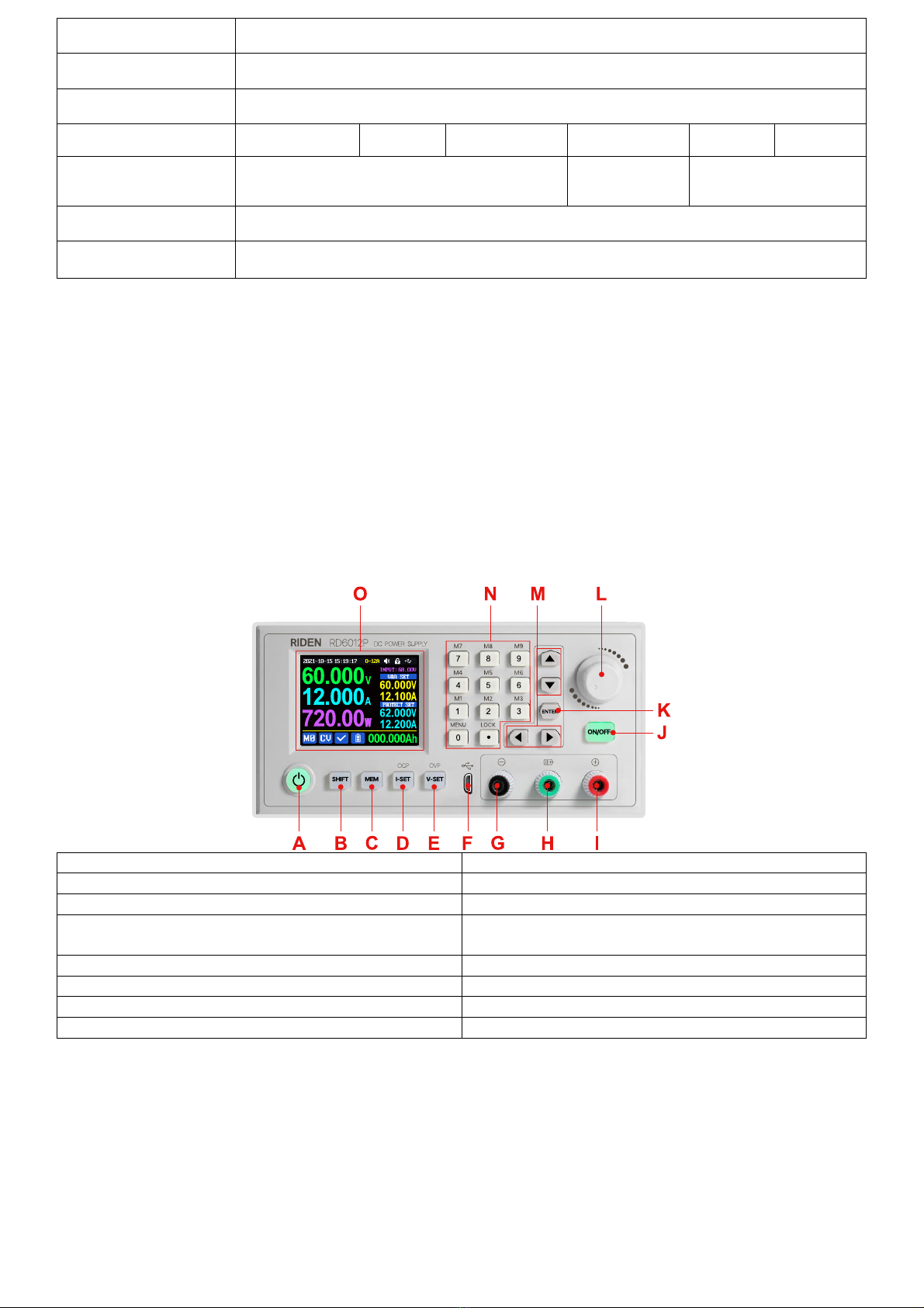
1.4.2.7 快捷数据组设置
主界面下按动 +键进入系统设置菜单,然后再按动两次
键进入(如图十四)存储设置主菜单:
按动 键进入菜单,按动方向键可以选择数据组,此时旋转编
码电位器可以在 6A、12A 两个电流量程指示中切换(仅限 RD6012P-W),
选择好量程后再设置参数。按动 键设定存储数据的输出电流设定值,
转动编码电位器可以直接调整,旋转调整不会超过限制,按动 或
键可以更改光标位置,也可以直接使用数字键盘输入按 键确认。
如输入错误,可以按动编码电位器取消。
按动 键可以设定存储数据的输出电压设定值,方法类似输出电
流设定值操作。
先按 +键或 +键可以设定存储数据的输出过流保护
设定值或输出过压保护设定值,方法类似输出电流设置。
数据设定完成后,按动编码电位器返回并保存数据。
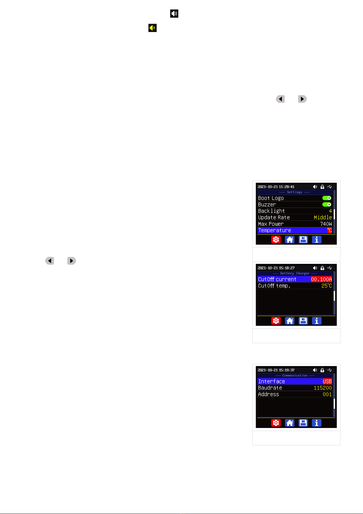
1.4.2.8 系统信息
主界面下按动 +键进入系统设置菜单,然后再按动三次
键进入(如图十五)系统信息主菜单:
Product Model: 产品型号,Product SN: 产品串号,Firmware: 固件版
本,Temperature: 系统温度。
图十一
图十二
图十三
图十四
图十五
10
Constant Voltage and Constant Current
DC Power Supply Instruction
Model: RD6006-W/ RD6006P-W /RD6012-W/RD6012P-W/RD6018-W/ RD6024-W
Date: 2022.9.9
Dear users, thank you for purchasing the constant voltage constant current DC power supply
produced by Hangzhou Ruideng Technology Co., Ltd. In order to let you know more about the full
function of this product, get a better experience and avoid misuse. Please read this instruction carefully
before using it. Keep it for future reference. This manual only contains the operation, for APP and PC
software, please check the download link:XXXXXXXXXXXXXXXXXXX
Note: This instruction is corresponding to RD6006-V1.38, RD6012-V1.38, RD6018-V1.38,
RD6024-V1.37, RD6006P-V1.41, RD6012P-V1.44, the page and operation may be different under
different firmware versions, please pay attention when using it. We do recommend you to download the
latest firmware for better experience.

11
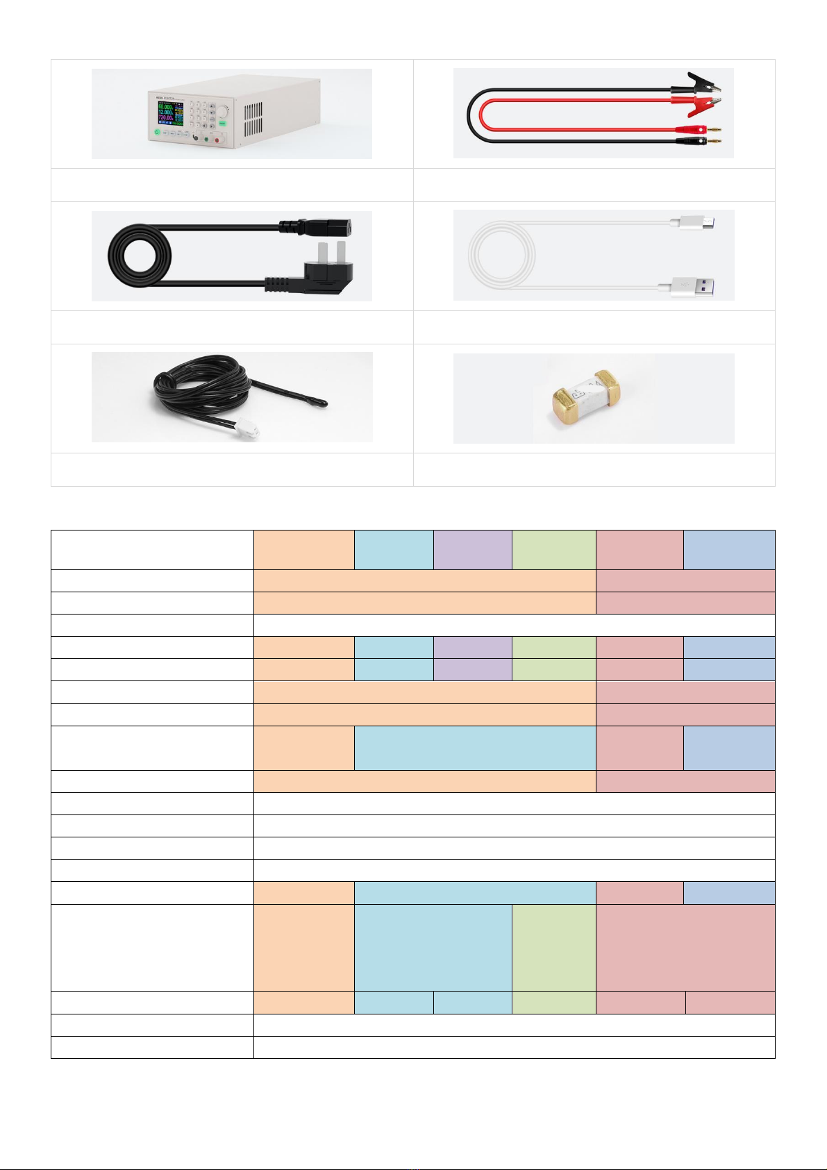
1.1 Accessory List
RD power supply*1
X25A output cable*1
Input AC Power Cord*1 这个头有好多标准
Micro Communication cable*1
(inside X25A bag)
External Temperature Sensor*1
Backup Fuse*1
1.2 Technical Parameter
Model
RD6006-W
RD6012-W
RD6018-W
RD6024-W
RD6006P-W
RD6012P-W
Input voltage range
6-70.00V
7-70.00V
Output voltage range
0-60.00V
0-60.000V
Output current range
0-6.000A
0-12.00A
0-18.00A
0-24.00A
0-6.0000A
0-12.000A
Output power range
0-360W
0-720W
(AC220V)0-1080W
(AC110V)0-950W
(AC220V)0-1140W
(AC110V)0-950W
0-360W
0-720W
Input voltage resolution
0.01V
Output voltage resolution
0.01V
0.001V
Output current resolution
0.001A
0.01A
0.0001A
0.001A/
0.0001A
Battery voltage resolution
0.01V
Input voltage accuracy
±(1%+5 digits)
Output voltage accuracy
±(0.3%+3 digits)
±(0.5‰+4 digits)①

12
Model
RD6006-W
RD6012-W
RD6018-W
RD6024-W
RD6006P-W
RD6012P-W
Output current accuracy
±(0.5%+5 digits)
±(1‰+6 digits)
Battery voltage accuracy
±(0.5%+3 digits)
Default battery charging
cutoff current
10mA
100mA
10mA
Output ripple typical
(VPP)
100mV
250mV@6A
100mV
@12A;
150mV
@24A
20mV②
Working temperature range
-10℃~40℃
External sensor
Temperature detection
range:
-10℃~100℃/0℉~200℉
External sensor
Temperature detection
accuracy:
±3℃/±6℉
Constant voltage mode
response time
2ms(0.1A-5A Load)
Constant voltage mode load
regulation
±(0.1%+2 digits)
Constant current mode load
regulation
±(0.1%+3 digits)
Capacity measurement
range
0-9999.99Ah
Energy measurement range
0-9999.99Wh
Capacity and energy
statistical error
±2%
Max output voltage
(input voltage÷1.1)-1
(input voltage÷1.1)-2③
Cooling fan start condition
Output
voltage>40V or
Output
current>4A or
System
temperature>45℃
Output current>8A or
System temperature>45℃
Output current>4A or
System temperature>50℃
Cooling fan shut down
condition when working
Output voltage
<40V and Output
current <3.9A and
System
temperature
<45℃
Output current <7.9A and System temperature <45℃
Output current <3.9A and
System temperature <50℃
Over temperature
System temperature >80℃
13
protection
Screen brightness setting
0-5(6 level)
Screen
2.4 inch color HD display
Weight(with package)
3kg
3kg
3kg
3kg
3kg
3kg
Product dimension
(cm)
17*8.5*33
17*8.5*33
17*8.5*33
USB communication
YES
WiFi communication
YES
①:Accuracy test method:1 digit is the minimum resolution, so the error under 5V is ±(5*0.5‰+4*0.001)=±0.0065V.
②:Ripple measurement method: noise and ripple are measured at X1 range, AC coupling, 20 MHz of
bandwidth on your oscilloscope with a 0.1uF parallel capacitor at the output terminals, pure resistor as load.
③:for example: input voltage is 24V,the max output voltage is 20.8V.
We will use RD6012P to introduce the appearance and operation
1.3 Panel Instruction
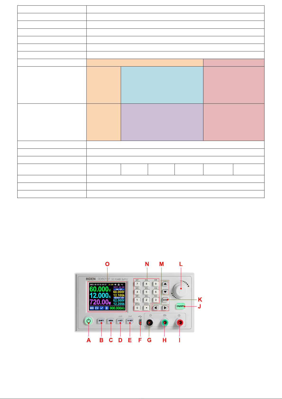
1.3.1 Front Panel
A: Power button
B: SHIFT Second function button
C: Quick storage button
D: Current/Over current protection setting
E: Voltage/Over voltage protection setting
F: Micro USB port
G: Power supply output negative terminal/
Battery charging negative terminal
H: Battery charging positive terminal
(Dedicated terminal for battery charging)
I: Power supply output positive terminal
J: Output switch
K: Enter/ Confirm button
L: encoder potentiometer/Cancel button
M: Direction button
N: keypad
O: Screen
1.3.2 Back Panel

14
P: Input power socket
Q: Rocker switch
R: External temperature sensor socket
S: Heat dissipation holes
1.4 Operation Instruction
After power-on, it will show boot image first, and then enters the main page.
1.4.1 Main Page
AA: Actual output voltage value
AB: Actual output current value
AC: Output power
AD: Current data group
AE: Constant voltage Constant current status
AF: Protection status indication
AG: Battery charging indication
AH: Battery related information display area
AI: Over current protection value
AJ: Over voltage protection value
AK: Output current preset value
AL: Output voltage preset value
AM: Input voltage
AN: Communication interface
AO: Button lock status
AP: Button tune
AQ: Current range
AR: Date time
Traditional Style
Detail Style
Curve Style

15
At main page you can press button to change the display style between Traditional Style,
Detail Style and Curve Style, the display style will not be saved automatically, you need to set default
boot display at section 1.4.2.6 Main Page Style Setting.
1.4.2 Operation Introduction
In the menu operation, the icon in red or cursor is the currently selected menu, press to
confirm or enter, press the encoder potentiometer to cancel or return, press the direction button to
move the cursor or switch menu, rotate the encoder potentiometer to change the setting, the settings
will be automatically saved when returning from the menu page. Press and hold the 0 button and power
on to restore the factory settings, press and hold the 1 button and power on to restore the factory
calibration value, press and hold and power on to enter the boot mode.
1.4.2.1 Battery Charging Function Introduction
After power on, at battery related information display area, external temperature, capacity and
energy will loop display. When the output is turned on: capacity, energy will be automatically
accumulated, and automatically cleared after power off.
The green terminal is connected to the positive electrode of the battery, and the black terminal is
connected to the negative electrode of the battery. After the battery is correctly connected, the battery
charging indicator turns red and the battery is connected. Press to start charging, the battery
charging indicator turns green . When the actual output current is lower than cut off current value
(10 mA, can be set by user), or the temperature that the external temperature sensor tested is greater
than the cut off temperature value, the output will be cut off automatically. Battery with protection
board needs to be charged with red and black terminals. The charging voltage and current should be set
on your own.
It is strongly recommended to use the original charger to charge the battery. The charging function
of this machine can only serve as a temporary replacement, not for long-term use. You need to know the
battery parameter well so that you can use it to charge, There is a risk of fire and explosion during the
charging process if you use the wrong way to charge.
1.4.2.2 Main Page Output Voltage and Current Setting
Press or button can switch the current range between 6A
and 12A. When you change the current range, the output will be turned
off
Press button to set the output current value, you can use
Figure 1
15:19:17 O-12A
60.000V
12.000A
720.00W
0MCV 000.000Ah
A12.200V62.000
protect setA12.100V60.000
V&a set
I NPUT: 68. OOV
Set Error

16
encoder potentiometer to adjust the output value directly. And you will not set the value which exceeds
the limit in this way, press button to move the cursor. Of course you can use keypad to type in the
value, and press to confirm, and it will save the set value and set current range, if you set a value
exceeds the limit, it will prompt like what shows in Figure 1. If you set the wrong value, you can press
encoder potentiometer to cancel.
Press button to set the output voltage value, the operation way is similar to output current
setting.
Press + button / + button to set the over current protection/ over voltage
protection value. The operation method is similar to output current setting. If you want to set the over
current auto cut off function, your OCP value should be higher than the Current setting value.
When the device is under constant voltage mode, it will show , and it will show when
under constant current mode; when the device works normally it will show at protection status
indication, when the actual output current value is higher than the over current protection value(OCP),
the output will be cut off automatically, and show , when the actual output voltage value is higher
than the over voltage protection value(OVP), the output will be cut off automatically, and show ,
when the system temperature is higher than 80℃, the output will be cut off automatically, and show
.
1.4.2.3 Data Group Quick Storage and Call out
Press + keypad button 1-9, you can store the output voltage
value, output current value, over voltage protection value, over current
protection value into the corresponding data group(as shown in figure 2).
then press to confirm, it will show at bottom left, you can
press button and choose “X”, then press ENTER to cancel, after change the setting value it will
show .
Press + keypad button 1-9 to quick call out the saved data (as
shown above in figure 3) from the corresponding data group. Press
to confirm, It will show ,
after change the setting value it will show . When disable the “Take
OK” option, it will be called out directly to change the data setting value,
no prompt.
figure 2
figure 3

17
is the default data group, when you edit the settings and press button or rotate encoder
potentiometer to change the setting and press encoder potentiometer to return, it will be stored into
automatically, or you go to the data group setting menu, change the setting and press encoder
potentiometer to return, it will save too, and it will not save by other settings.
1.4.2.4 Keypad lock and unlock
Press +to lock or unlock the keyboard. And the keypad will
be automatically locked when communication starts, there will be
displayed on the top (cannot unlock manually), at this time, the power
button can be used, pressing other button will show(as shown in figure 4),
the keypad will be automatically unlocked after 3 seconds when the
connection disconnected, there will be displayed.
1.4.2.5 System Setting
Press + to enter the system setting menu, the icon in Red shows the menu being chosen,
press or to enter the sub-menu, the option in blue is the option being chosen, you can
rotate the encoder potentiometer to change setting, and you can press
button to select menu.
Press + to enter the system setting menu showed in figure 5,
press or to enter the sub-menu.
Settings Sub-menu:
System language is is set to English by default. You can also set Simplified Chinese, French, Germany
and Russian language;
Take OK is set to ON by default, when you quickly call out a data group, there will be a prompt to let
you confirm, if you set OFF for this option, the settings will be edited directly when call out a data group;
Take Out is set to OFF by default, when call out a data group, it will keep the previous output status,
when set it ON, it will output directly when call out a data group.
Boot Power is set to OFF by default, when boot the device the output is cut off, when set it on, it
will automatically turn on the output after booting.
Boot Logo is set to ON by default, when boot the device, it will show the boot logo first, then enter
the main interface, when set it OFF, it will enter the main interface directly.
figure 4
figure 5
18
Buzzer is set to ON by default,it will show on the top, and you can hear the beep when press
the button. When set it OFF, it will show , there will not be beep when press the button.
Backlight is set to level 4 by default, it can be set between level 0-5.
Update Rate is set to Low by default, you can set it low/mid/high, it is the fresh rate of the real
output voltage and current.
Max Power is set to 740W by default, you can set it between 0-740W, it is the max output power. On
the top you can see the *1 icon, it is the adjustment magnification, you can press or to choose
the different magnification so that you can set the value quickly, The max output is default voltage priority
mode, when the setting voltage*setting current is higher than the max power, the device will
automatically
decrease the output current setting value. When used together with low power power source, it is
recommended to set the value as the rated power of the power source*95%;
Temperature unit is ℃by default, it can be switched between ℃and
℉(figure 6);
Battery Charger Sub-menu(figure 7):
Cut-Off Current is set to 10mA by default and it can be edited. On the
top you can see the *1 icon, it is the adjustment magnification, you can
press or to choose the different magnification so that you can set
the value quickly, when the real output current is lower than this set value,
the output will be cut off automatically.
Cut-Off Temp. is set to 60℃by default, when the external
temperature sensor detect over 60℃, the output will be cut off
automatically.
figure 6
figure 7
figure 8
19
Communication Sub-menu(figure 8):
Interface is set to USB by default, you can also set it to
WIFI/TTL/RS485, USB means the micro USB port, you can see on the
top when set it USB, and when the communication starts, it will show ;
You need to insert a WIFI board to use the WIFI function, and it will show
on the top, and when the communication starts, it will show ; TTL
is not available now; You need to insert RS485 module to use RS485, and it will show on the top,
and when the communication starts, it will show .
Address is set to 001 by default, you can set it between 001 and 255;
The Baud rate and address on the device should be same with the information on PC software or
APP. You can see more communication at PC software and APP section.
Date and Time Sub-Menu(figure 9):
Date and Time can be set from Year 2000 to 2100, press or you can select the option, and
use encoder potentiometer can adjust the value, it will be applied immediately when you change the
value, please do not set the wrong time.
1.4.2.6 Main Page Display Style Setting
figure 9
figure 10
figure 11
This manual suits for next models
5
Table of contents


