logo
Brands
  1. Home
  2. •
  3. Brands
  4. •
  5. MKS
  6. •
  7. Power Supply
  8. •
  9. MKS SM 1280 Specification sheet

MKS SM 1280 Specification sheet

This manual suits for next models

3

Other MKS Power Supply manuals

MKS PR 4000 F User manual

MKS

MKS PR 4000 F User manual

MKS 260 PS-7 User manual

MKS

MKS 260 PS-7 User manual

MKS PDR-C-1C User manual

MKS

MKS PDR-C-1C User manual

MKS 247D User manual

MKS

MKS 247D User manual

MKS 246C User manual

MKS

MKS 246C User manual

MKS FR 840 Specification sheet

MKS

MKS FR 840 Specification sheet

MKS PDR-D-1 User manual

MKS

MKS PDR-D-1 User manual

MKS 260 PS-3B User manual

MKS

MKS 260 PS-3B User manual

Popular Power Supply manuals by other brands

Monacor PS-12CCD instruction manual

Monacor

Monacor PS-12CCD instruction manual

VOLTIMA MagicBox 15 Installation and operating instructions

VOLTIMA

VOLTIMA MagicBox 15 Installation and operating instructions

Miller Auto Deltaweld 452 owner's manual

Miller

Miller Auto Deltaweld 452 owner's manual

BCP PUOUBK How to install

BCP

BCP PUOUBK How to install

HC 2210 manual

HC

HC 2210 manual

Agilent Technologies 6032A Service manual

Agilent Technologies

Agilent Technologies 6032A Service manual

Puls CT5.241 installation manual

Puls

Puls CT5.241 installation manual

OCZ ZX1250W Technical specifications

OCZ

OCZ ZX1250W Technical specifications

iseg ECH 238 manual

iseg

iseg ECH 238 manual

Agilent Technologies 6631B Service manual

Agilent Technologies

Agilent Technologies 6631B Service manual

Power XXL A Series instruction manual

Power

Power XXL A Series instruction manual

Renogy PHOENIX 300 user guide

Renogy

Renogy PHOENIX 300 user guide

HP 6200B Operating and service manual

HP

HP 6200B Operating and service manual

Epson Stylus Scan 2500 Product information sheet

Epson

Epson Stylus Scan 2500 Product information sheet

Pulsar GREEN POWER CCTV PoE POE044816 manual

Pulsar

Pulsar GREEN POWER CCTV PoE POE044816 manual

Puls MiniLine ML50.100 instruction manual

Puls

Puls MiniLine ML50.100 instruction manual

Puls AS-Interface SLA4.100 installation manual

Puls

Puls AS-Interface SLA4.100 installation manual

Kenwood PS-60 instruction manual

Kenwood

Kenwood PS-60 instruction manual

https://manuals.online logo
https://manuals.online logoBrands
  • About & Mission
  • Contact us
  • Privacy Policy
  • Terms and Conditions

Copyright 2025 Manuals.Online. All Rights Reserved.

SM1280D for line 3 x 208V
SM1280T for line 3 x 400V
SM1280U for line 3 x 480V
SWITCHING POWER GENERATOR
WITH EMBEDDED MICROCONTROLLER
FOR 6 KW MAGNETRON
TECHNICAL NOTE
(issue April 2017)
SM 1280
(Cover Rear)
File: SM1280_r7eng -April 2017 - Technical note: SM1280 page 1 of 27
SM 1280
SM 1280
CE Declaration of Conformity
Dichiarazione di Conformità CE
Manufacturer’s Name: MKS Instruments Italy s.r.l
Nome del Costruttore:
Manufacturer’s Address: Via Curie, 8 - 42122 Reggio Emilia - Italy
Indirizzo del Costruttore:
Product Description: Power supply for microwave generator
Descrizione del Prodotto: Alimentatore per generatore di microonde
Product Name: SM1280 (power supply) and TMx66- TM060(microwave generator head)
Nome del Prodotto: SM1280 (alimentatore elettrico) e TMx66 (generatore a distanza)
Model: SM1280D.xxx, SM1280T.xxx , SM1280U.xxx - TM066.xxx1 - TM060.xxx1
Modello:
The product described above is in conformity with the provision of the following European Directives:
Il prodotto sopra descritto è in conformità con le seguenti Direttive Europee:
2014/35/CE Harmonisation of the laws of the member States relating to electrical equipment designed for use within
certain voltage limits
Riavvicinamento delle legislazioni degli Stati membri relative al materiale elettrico destinato ad essere
adoperato entro taluni limiti di tensione
2014/30/UE Harmonisation of the laws of the member States relating to electromagnetic compatibility
Riavvicinamento delle legislazioni degli Stati membri relative alla compatibilità elettromagnetica
Conformity to the Directives is assured through the application of the following standards:
La conformità alle Direttve è assicurata tramite l’applicazione dei seguenti standards:
Reference number Edition Description
Numero di riferim Edizione Descrizione
EN61010-1 2011-03 Safety requirements for electrical equipment for measurement, control and laboratory use
Prescrizioni di sicurezza per apparecchi elettrici di misura, controllo e per utilizzo in laboratorio
EN61000-6-4 2007-11 Electromagnetic compatibility - Generic emission standard, industrial environment
Compatibilità elettromagnetica - Norma generica sull’emissione, ambiente industriale
EN61000-6-2 2006-10 Electromagnetic compatibility - Generic immunity standard, industrial environment
Compatibilità elettromagnetica - Norma generica sull’immunità, ambiente industriale
Reggio Emilia, April 2017. Marco Garuti
General Manager
page 2 of 27 File: SM1280_r7eng -April 2017 - Technical note: SM1280
SM 1280
Policy about Reduction on Hazardous Substances (RoHS) and Waste Electrical and Electronic Equipment
(WEEE)
Law Reference
• Directive 2012/19/EU of European Parliament (WEEE)
• Decreto Legislativo D.L. n. 49 – 14/03/2014 (WEEE)
• Directive 2011/65/Eu of European Parliament (RoHS)
• Decreto Legislativo D.L. n. 27 – 4/03/2014 (RoHS)
Risk Assessment on RoHS
The SM1280 magnetron power supply is RoHS compliant.
Important information to User about disposal, recycling, reuse of this electronic equipment at the end of its
useful life (WEEE Directive).
According Directive 2012/19/EU this equipment is not included on the list of categories/products covered by the Directive (as a
matter of fact it does not perform a function alone, must be included into a larger process equipment and it’s for stationary use).
Nevertheless we invite the User to respect the following Directive rules:
• this WEEE is not a municipal waste and should be collected separately according to rules of your country
• the symbol means that this WEEE cannot be disposal in the same place and in the same way like municipal waste
• this WEEE may present risk for environment as well as for person in case of disposal in unauthorized place, due to content
of hazardous substances
• fordisposalofthisWEEEinunauthorizedareatheUsermaybechargedwithaneorprosecutedbylaw.
Rev. Revision note Date File
0 First emission January 2009 SM1280_r0
1 Schematic diagrams corrected; alarm reset procedure added May 2009 SM1280_r1
2 CE declaration updated, new software release added December 2009 SM1280_r2
3 Application note reference AN 10290 October 2010 SM1280_r3
4 Software info added, TM060 v.1 head August 2012 SM1280_r4
5 New versions 20 (=1180) & 32 (RS485), logo update, removal int. schematic September 2013 SM1280_r5
6RoHS compliance statement. New version 22 direct replacement SM1180.
Removal vers. 32 (RS 485 serial command) September 2016 SM1280_r6
7 Updated norms. April 2017 SM1280_r7
File: SM1280_r7eng -April 2017 - Technical note: SM1280 page 3 of 27
SM 1280
SM 1280
Contents
A
Alarm troubleshooting 25, 26
B
Bit alarm table 19
BUS operation 14
C
CE Declaration 1
Cleaning 8
Components layout 21
Components List 22, 23
Conn.# 1 wiring vers. 0 - 1 - 2 -20-32: 16
Conn.# 1 wiring vers. 50 - 51 17
Conn.# 3, 4, 5 wiring 18
Conn.# 6 wiring 19
Conn. #8 wiring 14
Conn. RS232 wiring 20
Conn. #2-6 , wiring vers. 22 20-21
E
Environmental conditions 8
Equipment installation 8
Equipment ratings 9
F
Firmware upgrade 12
Fuses replacement 6
Fusesspecications  6
G
General description 4
General information 3
H
Handling instructions 9
Handling warnings 4
How to order 27
I
Internal settings 13
M
Manual commands 11
Meaning of ext. command vers. 0-2- 50 12
Meaning of ext. command vers. 1-51 14
Monitor signals 19
P
Power-up procedure vers. 0 -2 -0-50 10
Power-up procedure vers. 1 - 51 14
R
RoHS conformity 2
RS 485 version info (vers. 32) 15
T
Technical assistance 27
W
Warnings 3
Wiring instructions 9
Working modes vers. 0 - 50 10
Working modes Bus vers. 1 - 51 14
Working modes vers. 2 -20-32 11
General Informations
TheseequipmentsatisestheEuropeanStandardEN61010-1
With reference to EN 61010-1 standard, note:
these power supplies must be installed and serviced only by
qualiedpersonnel.
These power supplies must only be used by persons acquainted
with the regulations covering the application.
Theequipmentdescribedinthismanualhasbeenclassiedas
industrial,scienticandmedical(ISM)radio-frequencyequip-
ment and the related standard for the Electromagnetic distur-
banceistheEN55011(Industrialscienticandmedical(ISM)
radio-frequency equipment - Electromagnetic disturbance
characteristics - Limits and methods of measurement.)
With reference to Basic Standard EN55011, these power
supplies are included into Group 2 (Microwave generators,
Thyristor command equipment, Welding equipment, Induction
heating equipment or machine, Microwave industrial oven,
etc.), Class A (industrial environment): for this reason these
power supplies shall not be used in the residential, commercial
and light-industrial environment.
The SM1280x and TMx6x, when properly installed, comply
with the limits of radio disturbance characteristic of a Group2,
Class A equipment as stated by EN55011.
A copy of the tests performed may be sent on request. Note
thatthesetestscannotbeusedasaconformitycerticateofthe
user’snalequipment.
WARNINGS
The SM1280 is powered by industrial main line and has
high voltage output (close 8 kV): read carefully this manual
before using. Be sure of correct connections and use.
Failure to comply with the instructions enclosed in this
manual may involve considerable risks for the staff respon-
sible for checking and using the equipment, as well as the
risk of general malfunctions of the equipment itself.
page 4 of 27 File: SM1280_r7eng -April 2017 - Technical note: SM1280
SM 1280
Handling Warnings
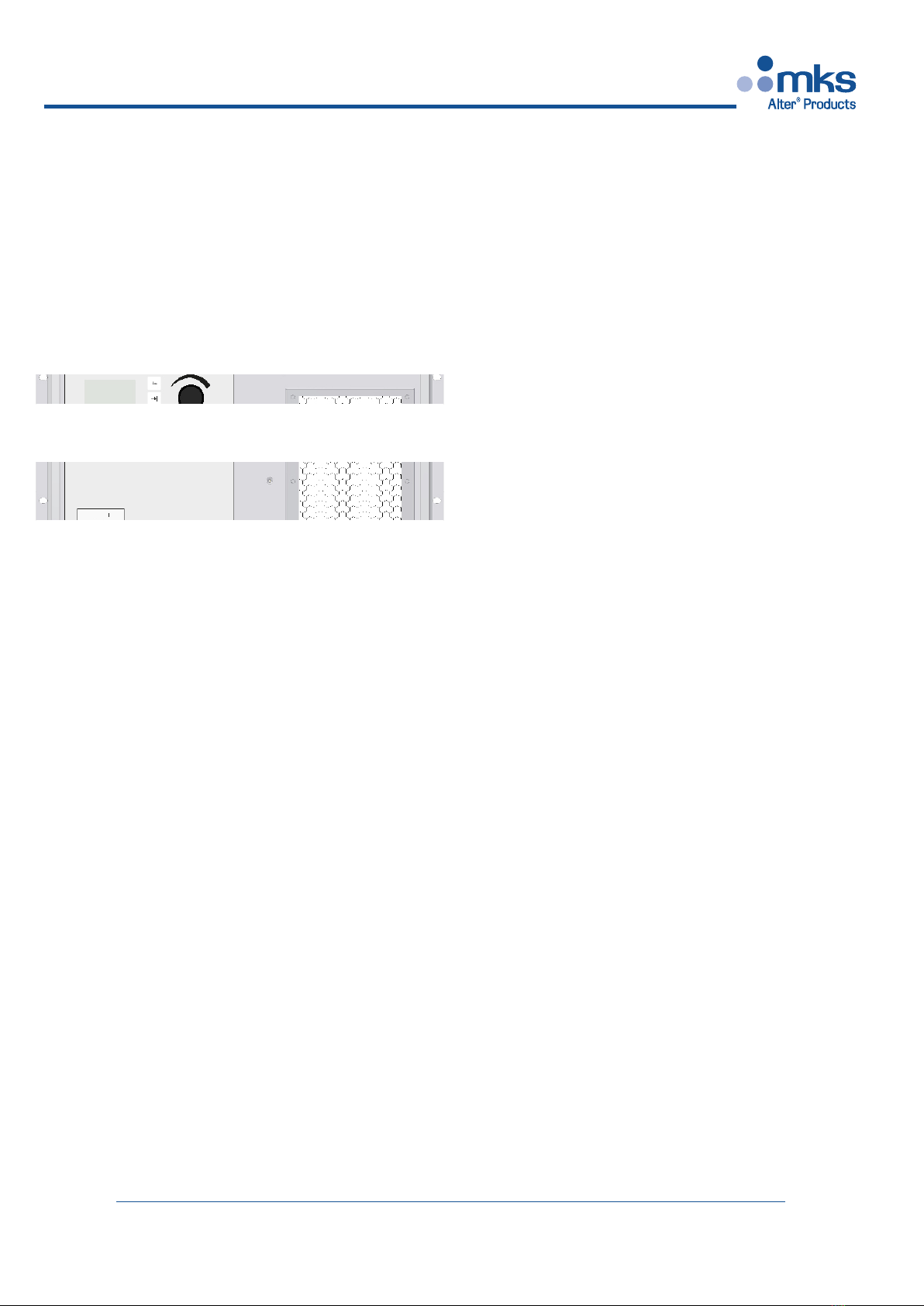
The SM1280x has two handles on the front panel to help
unpacking and handling operations: never use only the
handles to lift the equipment but support the weight with
an appropriate base on bottom!
The handles do not withstand the off-center weight of the
equipment (35 kg = 77 lbs).
General Description
The SM1280x is able to supply the power required by a
magnetron type YJ1600 (National) or PM60 (Panasonic) or
H3881 (Hitachi) or E 3327 (Toshiba), with nominal power of
6 kW @ 2.45 GHz.
The output power can be adjusted continuously, from 10% up
to 100%, using an external analog signal from 1 to 10Vdc,
orbyremotecontrol,throughledbusinterfaceorbyfront
panel commands, depending from model. The basic model
does not have any local command.
The unit, in addition to power the magnetron, has several
features and commands to control and power the magnetron’s
accessories.
The SM1280x has been developed to power and monitor our
remotable microwave head type TMx6x.
The SM1280x unit may also be used to power microwave
generators (heads) developed by others manufacturers under
condition that they are electrically compatible: moreover it is
mandatorytouseourlamenttransformerFIL200toguarantee
aproperlamentreductioncurve.Seetheelectricalspecica-
tions of the unit on the next pages.
The reduced height of the rack (only 7 HE, corresponding
to 310 mm) allows to use small cabinet, even in big plant:
i.e. in a standard cabinet with an height of 2 meters, arranged
to receive 19” racks, up to 5 SM1280x units may be easily
installed.
Theusermustprovideapropercoolingow:thecoolingair
enter into the unit from the front side, it passes through the
internal circuits and components, then it goes out from the
back.Theintakeairowisapprox.200m3/h.
The SM1280 is designed to be an alternative of the existing
SM1180 serie, when is needed a network connectivity, not
available on the previous model.
The SM1280 is available in both European and Japanese/US
voltages.
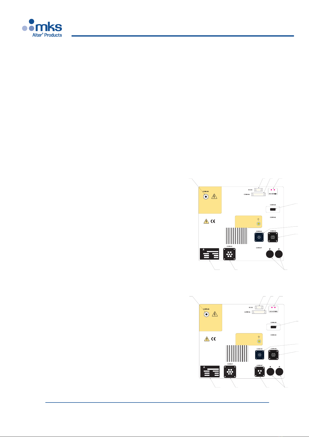
The SM1280 carries new features mainly driven by the new
CPU core and is offered in 6 versions:
- “Basic” version (vers. 0) has only one RS 232 standard port,
which allows to drive/manage the unit with a simple software
(like our “Front Panel” package distributed freely).
- “Bus” version (vers. 1) which implements an industrial bus
interfacelikeModbus/TCPorProbusorProNET,etc.,
allowing connection of multiple devices on the same bus.
-”Display” version (vers. 2) includes front panel commands
and LCD display as well as the features of the basic version.
- “Aux IN” version (vers. 50-51) has a separate connector
for input of Auxiliary voltage which allows to manage safety
shut-down of main power but keeping alive the unit’s CPU.
Thevers.51hasthesamecongurationwiththeeldbus
connector.
- “Legacy SM1180” version (vers. 22) is a full replacement
for installation that uses the former SM1180, except minor
changes. See relevant chapter.
-Seethenalchapater“Howtoorder”formoredetailsand
p/n.
SM1280 Range Overview
MODELABBREV. BASIC BUS DISPLAY AUX-IN Legacy
SM1180
Version no. 0 1 2 50 51 22
External Control (PLC) possible    
LED Panel Indicators   n.a. n.a. n.a.
Local Commands (Manual) n.a. n.a. n.a. n.a. 
Graphic Interface n.a. n.a. n.a. n.a. 
Network Control n.a. n.a. n.a. n.a.
RS 232 Control n.a.   n.a. 
Separate Input for Aux Voltages n.a. n.a. n.a.   n.a.
Firmware Upgrade      
*: Version 20 & 32 are not described in this manual. See past revision 5.
File: SM1280_r7eng -April 2017 - Technical note: SM1280 page 5 of 27
SM 1280
SM 1280
Description of versions 0 - 1 - 50 -51
The front panel includes 5 status LEDs:
POWER ON (GREEN): ON when power is present
INTERLOCK ON (WHITE): ON when Interlock chain
is closed (=OK)
READY(YELLOW):  ONwhenlamentisready
(Preheating timer is elapsed)
Flashing during preheating
time
MICROWAVE ON (BLUE): ON when microwave is
emitted (Enabling command
is ON)
ALARM (RED): ON when an alarm state is
present.
The rear panel comprises the following (see drawings):
1) 7 pins socket for main supply (CONN #1) [male]
2) 14 pins socket for mw head signals (CONN #4) [female]
3) socket for the high voltage output (CONN #5) [female]
4) 7 pins socket to power microwave head (CONN #3)[female]
5) 25 pins “D” type socket for I/O signals (CONN #6) [female]
6) RJ 45 on ETHERNET-MODBUS TCP interface, 9 pins “D”
type socket for CANOPEN/PROFIBUS interface [only models
with BUS interface, vers. 1 -51]
7) 9 pins “D” type socket for RS232 port [female]
8) fuse holders (F1, F2), screw type
9) 3 pins socket for main supply (CONN #7) [male, only
versions 50 - 51]
10) equipment label
11) BUS address switch [only models ves. 1 - 51]
WARNING!
REFER SERVICE TO QUALIFIED
PERSONNELONLY.
MAY PRESENT RISK OF
ELECTRICAL SHOCK INSIDE!
ACHTUNG!
NUR FACHKRAFTE DIEWARTUNG
MACHEN MUSSEN
MANSICHEINEN SCHLOG HOLEN!
ATTENZIONE!
LA MANUTENZIONE DEVE ESSERE
FATTADA PERSONALE QUALIFICATO.
RISCHIODI SCARICHE ELETTRICHE
ALL’INTERNO!
COLLEGAREALLATERRA
DEL GENERATORE REMOTO
VERBINDER DIRECT MIT DER
ERDUNG DES MIKROWELLEN GENERATOR
CONNECT DIRECTLYTO GROUND
OF MICROWAVE HEAD
1
2
3
4
5
6
7
8
9
0
1
2
3
4
5
6
7
8
9
0
BUS ADDRESS
CONN #6
CONN #4
CONN #3
CONN #1
CONN #8
CONN #2
CONN #7
F1 F2
ATTENZIONE!
USCITAALTA TENSIONE
WARNING!
HIGH VOLTAGE OUTPUT
WARNUNG!
HOCHSPANNUNGSAUSGANG
CONN #5
RS 232
46PP01280
1
2
4
8
3
6
75 11
9
CURRENT
DATES/N
POWER
INPUT FREQ.
REGGIOE.-ITALY
MODEL P/N
ar
e
t
l
KVA
V
A
Hz
10
REAR PANEL versions 0 - 2
WARNING!
REFER SERVICE TO QUALIFIED
PERSONNELONLY.
MAY PRESENT RISK OF
ELECTRICAL SHOCK INSIDE!
ACHTUNG!
NUR FACHKRAFTE DIEWARTUNG
MACHEN MUSSEN
MANSICHEINEN SCHLOG HOLEN!
ATTENZIONE!
LA MANUTENZIONE DEVE ESSERE
FATTADA PERSONALE QUALIFICATO.
RISCHIODI SCARICHE ELETTRICHE
ALL’INTERNO!
COLLEGAREALLATERRA
DEL GENERATORE REMOTO
VERBINDER DIRECT MIT DER
ERDUNG DES MIKROWELLEN GENERATOR
CONNECT DIRECTLYTO GROUND
OF MICROWAVE HEAD
1
2
3
4
5
6
7
8
9
0
1
2
3
4
5
6
7
8
9
0
BUS ADDRESS
CONN #6
CONN #4
CONN #3
CONN #1
CONN #8
CONN #2
CONN #7
F1 F2
ATTENZIONE!
USCITAALTA TENSIONE
WARNING!
HIGH VOLTAGE OUTPUT
WARNUNG!
HOCHSPANNUNGSAUSGANG
CONN #5
RS 232
46PP01280
1
2
4
8
3
6
75 11
CURRENT
DATES/N
POWER
INPUT FREQ.
REGGIOE.-ITALY
MODEL P/N
ar
e
t
l
KVA
V
A
Hz
10
REAR PANEL version 1
REAR PANEL versions 50 - 51
FRONT PANEL versions 0-1-50-51
page 6 of 27 File: SM1280_r7eng -April 2017 - Technical note: SM1280
SM 1280
Description of versions 2 - 22
The front panel of the “Display version” (vers. 2), as well as
that of version 22 (Legacy version) includes a graphic display
and manual commands.
The unit can be driven manually through local commands (all
these versions), alternatively via remote I/O discrete channels,
via RS 232 serial port with our standard “FrontPanel” software
FRONT PANEL version 2 - 22
REAR PANEL version 22
The version 22 (called “Legacy SM1180) is a direct repla-
cement for SM1180 in versions 2, 3, 4, 5 : there is just one
wiring change, linked to the HV output [3], because the
SM1180 had a 4 pole LH type connector and the SM1280 uses
the single pole GES type HV connector.
The back panel of vers 22 (see below) has the same connetor
style, size and pin-out like the SM1180
Plsrefertothespecicschematicofversion22forwiringat
page 16 and following
Fuses specications
(all versions)
The SM1280x has 2 fuses installed on the rear panel (look at
the drawing on page 5, position 8): both fuses, labelled F1 and
F2, protect the output line powering the remote head.
A third fuse is on the main board M416, to protect internal
control circuitry.
Fuse F1 and F2 specs:
- Size, type: 10x38 mm, ceramic cartridge
- Speed action: quick (F)
- Rated current: 6 A
- Rated voltage: 500 V
Fuse F1 specs on M416 board:
- Size, type: 5x20 mm
- Speed action: slow (T)
- Rated current: 3,15A
- Rated voltage: 250 V
File: SM1280_r7eng -April 2017 - Technical note: SM1280 page 7 of 27
SM 1280
SM 1280
SM 1280 Ratings & Specications
Description Units Value Function Note
SM1280T: Line input nominal:
Working voltage range
Max Absolute voltage:
Input Current, max:
Vac
Vac
Vac
Arms
3x400
360÷440
450
18.5
Power input, 3 phase + GND
@400V input, full power
CONN #1, pin 2-3-7
See wiring schematic
SM1280D: Line input nominal:
Working voltage range
Max Absolute voltage:
Input Current, max:
Vac
Vac
Vac
Arms
3x208
185÷230
300
30
Power input, 3 phase + GND
@208V input, full power
CONN #1, pin 1-4-6
See wiring schematic
SM1280U: Line input nominal:
Working voltage range
Max Absolute voltage:
Input Current, max:
Vac
Vac
Vac
Arms
3x480
390÷570
600
14.5
Power input, 3 phase + GND
@480V input, full power
CONN #1, pin 2-3-7
See wiring schematic
Transient Overvoltage Cat. II According IEC 664
Output power, max Wdc 8500 Electrical power to magnetron input
Electrical efciency (Out/In) 92% Max heat to dissipate ~ 700 W
Output current range: mA 120÷1200 Adjustable range 10÷100%
Output current max: mA 1200 Limit in Power Control Mode With max amb temp. 40°C
Output voltage, max: Vdc 7800 Characteristic of magnetron Range 7.4÷7.8 kV
Output ripple, max ±4.5%@ 300 Hz
±3% @ 40 kHz Ripple in current at max power
Output linearity: Wdc ±15 Corresponding to ~ 10 Wrf
Output stability: 1% For input uctuations within ±10%
Filament pre-heating time sec 15 Preheat lament at Power
ON or after Hibernate is OFF When done, READY signal is ON
Magnetron power:
[Frequency]
kW
MHz 6
[2450 ]
Typical: YJ1600, H3881,
PM60, AM3881, E Selectable lament backdown curve
for the specic tube
Enabling signal, digital input: Vdc +24
Range 5÷30 ON/OFF output & alarm reset
Input Z: 4k7 kOhm CONN #2, pin 4. To reset alarm hold
OFF for 2 seconds
Response time to full power: msec 80 Linear time Using Enabling signal
Response time to switch OFF: msec 20 Using Enabling signal
Pulsability of output, min TON msec 100 Max power 6 kW, Freq= 5 Hz Using Enabling signal
Switch OFF time for alarm msec 3 Automatic shut-off
Reference signal, analog input: Vdc 1÷10 Power control 10÷100% CONN #6, pin 5. Ground pin 18.
Input Z=50 kOhm, optoinsulated
Alarm contact, general:
Contact rating: max voltage
max current: V
mA 30
500
OPEN: Alarm state or power
OFF
CLOSED: OK
CONN #6, pin 1-14
Alarm code, 4 bit contacts (0/1)
Contact rating: max voltage
max current V
mA 30
100
Inform type of alarm with
emission of 4 bit code
See relevant table
CONN #6, pin 8-21-9-22 (bit 0...3)
Common pin 13
Ready contact:
Contact rating: max voltage
max current V
mA 30
500
CLOSED when lament is
pre-heated & ready
OPEN not ready lament or
Alarm state
CONN #6, pin 12-24
Hibernate signal, digital input: Vdc +24
Range 5÷30 ON lament is hibernate.
OFF or not used:lament heated
CONN #6, pin 11
Z= 4k7 kOhm
Interlock contact: OPEN: Alarm, shut OFF
outputs. CLOSED: OK CONN #6, pin 10-23
Monitor signals, analog outputs (2): Vdc 0÷10 Monitors various parameters
Max current: 10 mA
See relevant schematic
CONN #6, pin 2-15 (1); pin 3-16 (2)
Designed for receiver impedance
>30 kOhm (for accuracy <1%)
Voltage output (internal generator) Vdc +24÷30 Auxiliary voltage genera-
tor, unregulated, for user
interface
CONN #6, pin 10, 20. Max current:
100 mA
page 8 of 27 File: SM1280_r7eng -April 2017 - Technical note: SM1280
SM 1280
Equipment maintenance
Cleaning
Cleaning of air inlet: verify once a month. In case you need
to remove dust then proceed as follow:
- remove main line from the unit
- remove the cover
- use pressurized air from inside to outside for short time: do
not exceed or you may damage the fan
- install the cover and then power-on again.
Fuses replacement
To replace the fuses on rear panel proceed as follow:
- switch-off the unit, removing main line from the equipment;
- unscrew fuseholder cap;
- replace the fuse with a new one with the same electrical
characteristics;
- inspect also the fuseholder: if it’s oxidated or it has burned
point then replace it;
- install the fuseholder cap and screw tight.
Internal fuse:
- switch-off the unit, removing main line from the equipment
- remove the unit cover, unscrewing the 6 screws on sides
- locate the fuseholder on M416 pcb: push the cap then rotate
it without any tool (gently!), pull up the cap and inspect the
fuse;
- replace the fuse with a new one with the same electrical
characteristics
- install the fuseholder cap: push it then rotate.
- reassemble the unit cover, screwing the 6 screws on sides
Equipment installation
The SM1280x cannot operate on a bench: it must be installed
into a proper cabinet like a commercial 19” standard enclo-
sure.
The equipment is intended for industrial use only, not for
laboratory use, and user must respect the wiring norms and
prescriptions as described into next paragraph (“Wiring
instruction”).
The equipment cannot operate cantilevered, it must be safely
xedinsideacabinetbymeansofscrewsonthefrontpanel
(which is provided with 4 holes) and supported by means of a
proper frame on the bottom for, at least, 3/4 of the total depth.
Usually two “L” shaped supports on each side of the equip-
ment, having a dimension of mm 15(h) x 30(l) x 2 (thick) are
suitable for that purpose.
Therearsideoftheequipmentmustbeprotectedbyaxed
panel which can be removed only by means of tools or by a
door with security micro-switch: when the door is opened the
micro-switch must shut-off the main line. This safety precau-
tions must be taken to avoid operations on rear fuses or on
connectors while the unit is still powered.
Special attention must be taken on designing the cooling air
owincaseofstackingseveralunitsintothesamecabinet.
Environmental & Physical Characteristics:
Use: Indoor use only, within industrial
enclosure
Working temperature range 5÷40°C [41÷104°F], Min-Max
ambient temperature
Altitude design criteria: for altitude up to 2.000 m
Working Humidity range 80% RH up to 31°C [88°F],
decreasing linearly to 50% RH
at 40°C [104°F]
Air cooling requirement, ow: m3/h 200 Input from front panel.
Air clean from dust
Pollution degree: 2, complies with IEC 664
Total Weigth: kg 35 [77 lbs).
Rack Dimensions, Panel Width:
Panel Heigth:
Length (Depth):
mm 480 [19”]
mm 310 [12.2 “ - 7HE/U]
mm 482 [19” ]