HANKISON SPXFLOW HF Series User manual

HF Series
Compressed Air Filters
Models HF(grade)-52 through HF(grade)-92 Standard, High Pressure and Corrosion Resistant Models
FORM NO.: 4011208 REVISION: 10/2015 READ AND UNDERSTAND THIS MANUAL PRIOR TO OPERATING OR SERVICING THIS PRODUCT.
INSTRUCTION MANUAL

Contents
MODEL NUMBER CONFIGURATION ..................... 1
1.0 INSTALLATION ............................................... 2
2.0 OPERATION .................................................. 5
3.0 MAINTENANCE............................................. 6
DIMENSIONS AND WEIGHTS ........................................ 8
WARRANTY ......................................................... 9
General Safety Information
1. Pressurized devices
• Donotexceedmaximumoperatingpressure
indicatedonserialnumbertag.
• Makecertainlterisfullydepressurizedbefore
servicing.
2. Breathing Air
• Airtreatedbythisequipmentmaynotbesuit-
ableforbreathingwithoutfurtherpurication.
RefertoOSHAstandard1910.134forbreathing
airrequirements.
3. Flammable gases
Thematerialsofconstructionusedinthisproduct
arecompatiblephysicallywithammablegases,
however,thereareapplicationlimitationsforthis
productwhenusedwithammablegases.Each
application(otherthanairorinertgas)shouldbe
carefullyreviewedtominimizethechancesof
creatingareorexplosionhazard.
IMPORTANT
Tightencartridgesbeforeuse.Cartridgesmay
haveloosenedduringtransit.Toensureatight
sealbetweenthecartridgeendcap(s)andinlet
manifold,openvesselandturncartridgeclockwise
(asseenfrombottom)untilhandtight.See
Section3.0,Bforinstructionsonenteringvessel.

1
Grade Identification
Filtergradecanbeidentiedbythethirddigitofthemodelnumber.Inaddition,elementswithafoamouter
sleevecanbeidentiedbycolor.
Grade Description Type Outer foam color
11 Mechanical Separator Impaction type separator none
9 Separator/filter Mechanical separator and 3 micron coalescer none
7 General purpose air line filter 1 micron coalescer none
6 Dry Desiccant Afterfilter 1 micron after-filter for desiccant dryers none
5 High efficiency oil removal filter High efficiency (99.99+%) coalescer Red
3 Maximum efficiency oil removal filter Maximum efficiency (99.999+%) coalescer Blue
1 Oil vapor removal filter Activated carbon adsorber Green
Model Number Configuration
HF (1) -(2) -(3) -(4)
1. Filter Grade is indicated in space (1).
2. Housing Number is indicated in space (2).
3. Connection Size is indicated in space (3)
4. If optional corrosion proof stainless steel cores are included, an S
is indicated in space (4). Corrosion resistant stainless steel cores
are standard.
Example: A Grade 5 high efficiency oil removal filter with a capacity of
1250 scfm and 3” NPTM connections would be configured
as: HF 5-56-24-G
(2) Housing (3) Connection Sizes
Number
Capacity
scfm [m3hr] @
100 psig [7 kgf/cm2]
52 625 [1110] 24 - 3” NPTM 80 - DN 80 Flange
54
56
1000 [1700]
1250 [2125] 24 - 3” NPTM 80 - DN 80 Flange
60 1875 [3158] 24 - 3” NPTM 80 - DN 80 Flange
64
68
2500 [4250]
3125 [5310] 4F - 4” ANSI Flange 100 - DN 100 Flange
72 5000 [8490] 6F - 6” ANSI Flange 150 - DN 150 Flange
76
80
6875 [11,670]
8750 [14,850] 6F - 6” ANSI Flange 150 - DN 150 Flange
84 11,875 [20,175] 8F - 8” ANSI Flange 200 - DN 200 Flange
88 16,250 [27,610] 8F - 8” ANSI Flange 200 - DN 200 Flange
92 21,250 [36,100] 10F - 10” ANSI Flange 250 - DN 250 Flange
(4) Features
D= Internal Automatic Drain
Mechanism
G= Differential Pressure Gauge
Indicator
S = Corrosion Proof Stainless
Steel Element
M= Filter Monitor
(1) Filter Grade
11 - Mechanical Separator
9- Separator/Filter
7- Air Line Filter
6- Dry Desiccant Afterfilter
5- High Efficiency Oil Removal Filter
3- Maximum Efficiency Oil Removal Filter
1- Oil Vapor Removal Filter

2
1.0 Installation
A. Where Used/Air Quality After Filtration
Grade Where used
Solid particle
removal (maximum
size in microns)
Liquid removal
efficiency (at
rated conditions)
Maximum inlet
liquid loading
ppm w/w
Remaining
oil content
ppm w/w
11
Separator - downstream of an aftercooler
Point-of-use - where no aftercooler is installed
upstream
— 95% of water 30,000
bulk liquids —
9
Separator - downstream of an aftercooler
Point-of-use - where no aftercooler is installed
upstream or as prefilter to refrigerated dryer
3 99+% of water
25,000
aerosols &
bulk liquids
5
7
Prefilter -
•PreltertoGrade3&Grade5highefciency
coalescing filters
Point-of-use - where aftercooler is installed
upstream
1 100% of water 2, 000
aerosols
1
aerosols
6
Afterfilter - downstream of a pressure-swing
(heatless) desiccant dryer
•DownstreamofanActivatedCarbonor
Desiccant Tower
1No liquid should be
present at inlet
No liquid should be
present at inlet —
5
Prefilter
•Aheadofdesiccantandmembranedryers
Afterfilter
•Downstreamofrefrigerateddryer
•Downstreamofpressure-swing(heatless)
desiccant dryers for finer solid particle removal
•Oilremovalatpoint-of-use
0.01 99.99+% of oil 1, 000
aerosols
0.008
aerosols
3
Prefilter - ahead of desiccant and membrane
dryers (use after Grade 7 to reduce liquid and
solids load, prolong element life and ensure
filtration efficiency)
Afterfilter - downstream of refrigerated dryer
0.01 99.999+% of oil 100
aerosols
0.0008
aerosols
1Afterfilter to Grade 3 & Grade 5 for true oil free
applications 0.01 Removes vapors
only
No liquid should be
present
0.003
vapor

3
B. Piping
1. Beforeinstalling,blowoutpipelinetoremove
scaleandotherforeignmatter.
2. Mounting(Grades11,9,7,5,3)-mountsothat
inletandoutletconnectionsarehorizontal(lter
bowlvertical)toensureproperliquiddrainage.
3. FlowDirection-installsothattheairowisinthe
directionindicatedonlter.
NOTE:Grade6owsfromoutsidetoinsideof
element.Allothergradesowfrominsideto
outside.Observeowarrowsonunit.
4. Isolationvalvesandby-passpiping-Foreaseof
service,isolationandby-passvalvesaredesirable.
Incriticalapplications,twoltersinstalledinparal-
lelmaybenecessarytoavoidinterruptionofair
supply.
C. Drain Provisions (Grades 11, 9, 7, 5, 3)
Thebottomofthepressurevesselisprovidedwith
adrainplugforshippingpurposes.Provisionfor
manualorautomaticdrainingisnecessaryforproper
operation.
Donotattempttoremovedrainplugif
theunitispressurized.
1. ManualDrain-Whendrainingisperformedmanu-
allyonaregular,periodicbasis,asimple(open/
shut)valvemaybeusedtodrainthevessel.When
drainingmanually,thevalveshouldbeopened
slowlytoavoidrapiddepressurizationandpossible
elementdamage.
2. AutomaticDrain-Whereregularmanualdraining
isnotperformed,anautomaticcondensatedrain
shouldbeused.Avarietyofdrainsisavailable
fromthemanufacturer.
SNAP-TRAP®TRIP-L-TRAP®
1" DRAIN PORT
FILTER
HOUSING
MANUAL
OVERRIDE
22
MIN
SEC
1
7
15
145
POWER
ON
ELECTRIC DRAIN
4
NOTES:
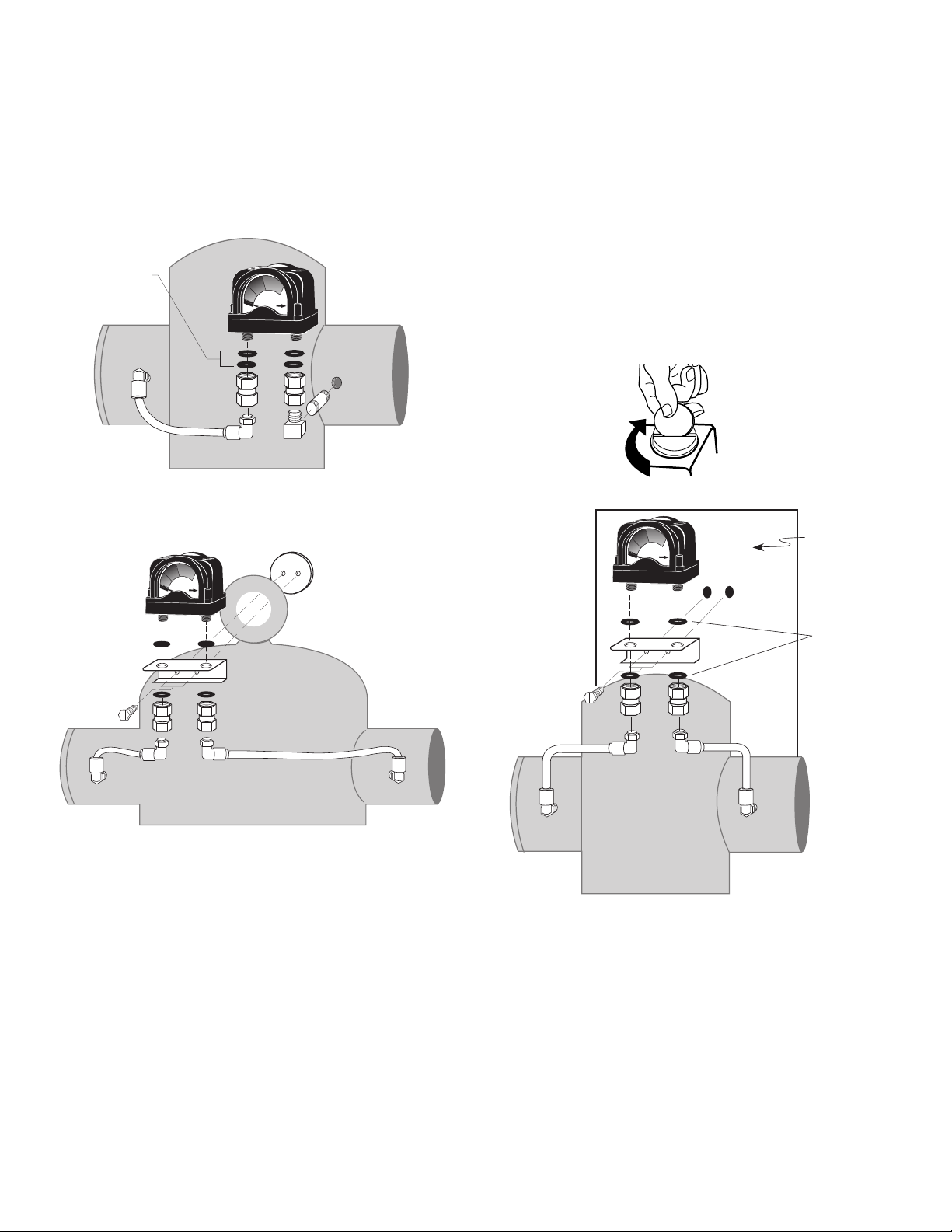
1) Makecertaino-ringsareinplaceonthebottom
ofthegaugebody.
2) Connectthelowpressuretransmissionbolt(bolt
nexttoREDbandongauge)tothegaugeportat
thelteroutlet(down-streamsideoflter).
3) Connectthehighpressuretransmissionbolt(bolt
nexttoGREENbandongauge)tothegaugeport
atthelterinlet(upstreamsideoflter).
4) Torqueboltsto25+/-5inchoz.Aathead
screwdriverwitha3/8”(1cm)minimumblade
widthcanbeusedtoassemble/disassemblethe
gauge.Smallbladewidthswilldamagethebolt
heads.DO NOT OVER TIGHTEN
WALL
INLET OUTLET
O-RINGS
All Models - Wall Mounted
D. Differential Pressure Gauge (DPG) -
Grades 9, 7, 6, 5, 3
Onstandardunits,agaugeandinstallationkitare
shippedseparatelypackagedforeldinstallation.
Refertodiagramforproperinstallation.Gauge
maybeinstalledonlterhousingoronanearby
wallusingthewallmountingbracketsupplied.
INLET OUTLET
O-RINGS
Model 52 - Equipment Mounted
Model 54 and Larger - Equipment Mounted
5
2.0 Operation
Donotoperatelteratpressuresinex-
cessofMaximumWorkingPressureindicatedonSerial
NumberTag.
NOTE:MaximumOperatingTemperature-150°F,
66°C.Liquidltrationabove120°F,49°Cisnotrecom-
mendedsincethereistypicallyoilpresentinavapor
statewhichpassesthroughthelterandcondenses
downstream.
NOTE:Grade1-Ifoperatedabove100°F,38°C,a
Grade1ltermayexperiencelessthan1000hoursof
lifebecauseofgreateroilvaporcontent.
A. Operational Checkpoints
Grades 11,9,7,6,5,3
1. Grades9,7,6,5,3-Checkpressuredropacrossthe
lter
a. Pressuredifferentialinexcessof6psi(0.42kgf/
cm2)-pressureindicatorinredarea-indicates
thattheltersleeveorelementshouldbe
replaced.
NOTE:Elementshouldbechangedannuallyorwhen
indicatorchangestored,whicheveroccursrst.
NOTE:Pressuredropshouldneverexceed15psi
(1.0kgf/cm2).
NOTE:Grades9,7,5,3-Pressuredropmaytemporar-
ilyincreasewhenowisresumedafterowstoppage.
Pressuredropshouldreturntonormalwithinone
hour.
b. Checkforsuddenreductioninpressuredrop.
Thismightindicate:
(1) Possibleleakacrosselemento-ringseal
(2) Leakthroughtheelementduetophysical
damage
2. Checkow,pressure,andtemperaturetomake
certainlterisbeingoperatedwithindesign
conditions.
3. Grades11,9,7,5,3-Checktoseethatlteris
installedleveltoinsureproperdrainage.
4. Grades11,9,7,5,3-Checkthatmanualdrainsare
drainedperiodicallyorthatautomaticdrainsare
functioning.
Grade 1
1. Checkforanoilysmellbyopeningthemanual
valve.Ifanoilysmellexists,thefollowingshould
bechecked:
a. Filterelementadsorptioncapacityexhausted
b. Leakacrosselemento-ringseal
c. Leakthroughelementduetophysicaldamage
d. Presenceofliquidsbecauseoflackoforfailure
ofprelters
e. Flow,pressureandtemperaturesoutsidede-
signconditions
f. Presenceofgaseousimpuritieswhichcannot
beadsorbedbyactivatedcarbon
Methane,carbonmonoxide,carbondi-
oxideandvariousinorganicgasescannotberemoved
byaGrade1lter.
C. Flow Capacity
Maximumairowforthevariousltersat100psig
(7kgf/cm2)isindicatedinTable1.Todetermine
maximumairowsatinletpressuresotherthan100
psig(7kgf/cm2),multiplyowfromTable1byairow
correctionfactorfromTable2thatcorrespondstothe
minimumoperatingpressureattheinletofthelter.
NOTE:Filtersshouldnotbeselectedbypipesize.
Selectusingowrateandoperatingpressureonly.
Table 1 - Maximum Flow @100 psig [
7 kgf/cm
2
]
Housing scfm [m3/hr]
52 625 [1110]
54 1000 [1700]
56 1250 [2125]
60 1875 [3158]
64 2500 [4250]
68 3125 [5310]
72 5000 [8490]
76 6875 [11,670]
80 8750 [14,850]
84 11,875 [20,175]
88 16,250 [27,610]
92 21,250 [36,100]
Table 2 - Air Flow Correction Factor
Maximum
Inlet
Pressure
psig 20 30 40 60 80 100 125 150 175 200
kgf/cm21.4 2.1 2.8 4.2 5.6 7.0 8.8 10.6 12.3 14.1
Correction Factor 0.30 0.39 0.48 0.65 0.82 1.00 1.22 1.43 1.65 1.87
Maximum
Inlet
Pressure
psig 250 300 350 400 450 500 550 600 650 700
kgf/cm217.6 21.1 24.6 28.1 31.6 35.2 38.7 42.2 45.7 49.2
Correction Factor 2.31 2.74 3.18 3.62 4.05 4.49 4.92 5.36 5.80 6.23
6
3.0 Maintenance
A. When to Replace Filter Element
NOTE:Grades7,6,5,3,1-completeelementisre-
placed;Grade9-unlessseparatorcoreisdamaged
outersleeveonlyisreplaced.
1. Grades6(drydesiccantafterlter)
Initialdrop:1psi(0.07kgf/cm2).Pressuredrop
increasesaselementloadswithsolidparticles.Re-
placewhenpressuredropreaches10psi(0.7kgf/
cm2)(indicatorinredarea)orannually,whichever
occursrst.
2. Grade11(mechanicalseparator)
Elementshouldnotrequirereplacementunless
physicallydamaged.Ifsludgeaccumulates,ele-
mentcanberemovedandcleanedwithsoapand
water.
3. Grades9,7,5,3(coalescinglters)
a. Initial(dry)pressuredrop:1psi(0.07kgf/cm2)
to2psi(0.14kgf/cm2)
b. Operatingpressuredrop:Aslterbecomesliq-
uidloaded(wetted),pressuredropwillincrease
to2to6psi(0.14to0.42kgf/cm2).Further
pressuredropoccursaselementloadswith
solidparticles.
FORMAXIMUMFILTRATIONEFFICIENCY,REPLACE
ELEMENTWHENPRESSUREDROPREACHES6PSI(0.42
KGF/CM2)(INDICATORINREDAREA)ORANNUALLY,
WHICHEVER OCCURS FIRST.
NOTE:Pressuredropmaytemporarilyincreasewhen
owisresumedafterowstoppage.Pressuredrop
shouldreturntonormalwithinonehour.
NOTE:Grades5and3-Duringnormaloperation
bottomoffoamsleevewillhaveabandofoil.
Spottingabovethebandindicatesthatliquidsare
accumulatingfasterthantheycanbedrainedandthat
preltrationisrequired.
4. Grade1(activatedcarbonlters)
a. Adsorptioncapacity-1000hoursatrated
capacity.Elementlifeisexhaustedwhenodor
canbedetecteddownstreamofthelter.
SEAL PLATE
VESSEL
YOKE
NUT
GASKET
TILT THE SEAL PLATE
AND GASKET TO FIT IN OPENING
HAND HOLE
Handhole
O-RING
PLASTIC
SEAL RING
RETAINER
LOWER
BOTTOM
OF SHELL
Model 52
B. Procedure for Element Replacement
THIS FILTER IS A PRESSURE CONTAINING
DEVICE. DEPRESSURIZE BEFORE SERVICING.
1. By-passtheltertopermit
servicing.
2. Depressurizethelteras-
semblyslowlybyopening
blowdownvalve.
3. Openpressurevessel
3A.Model52-Removeange
bolts.Lowerbottom
shell,o-ring,andsealring
retainer.
3B.Modelswithhandhole
a. Removenutandyoke
b. Liftsealplateandturnsothatsealplateand
sealplategasketcanberemoved.
3C.Modelswithangedbottom
a. Loosenbottomblindangebolts.
b. Removeallbutonebolt.
c. Swingangetooneside.
Bottom Flange
4. Startinginthecenter,unscrewthelterelements
andremovethelterelementsandelemento-
rings.
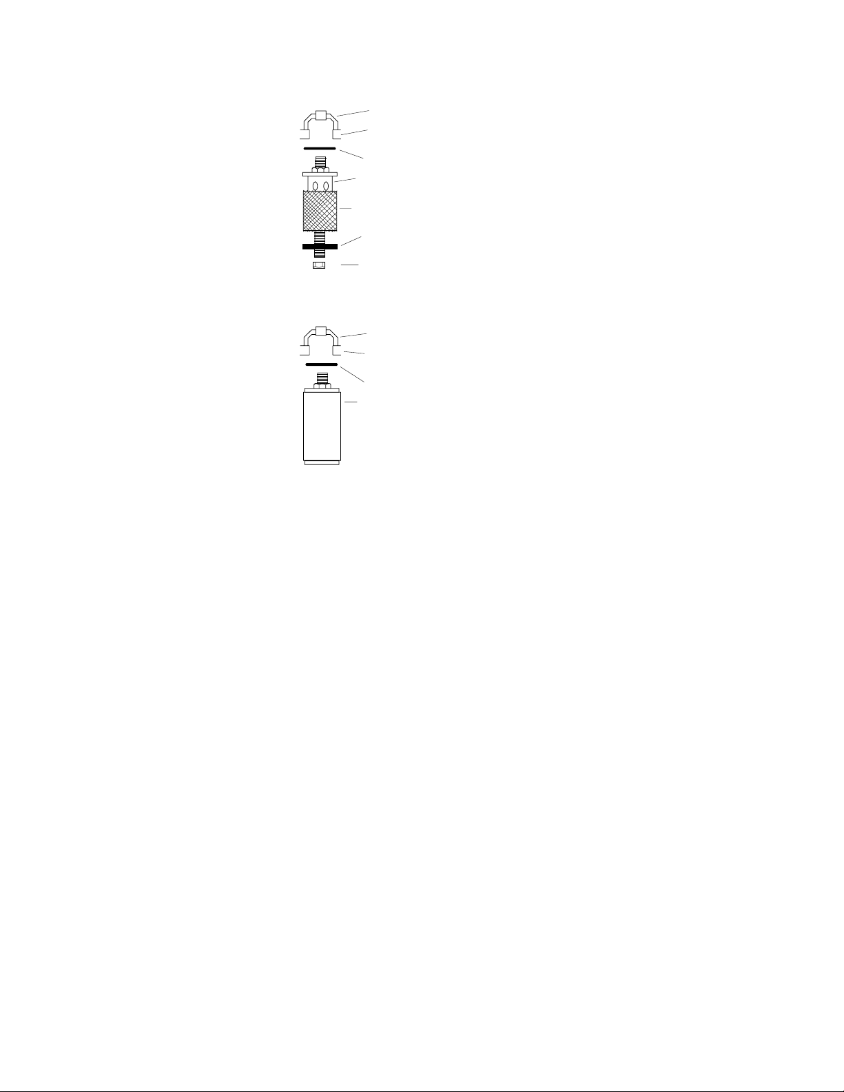
7
5. Grades7,6,5,3,1-Discardoldelementsando-
rings.
5A.Grade9
a. Removenylonnutand
bottomcap
b. Slidedisposablelter
sleevedownoversepa-
ratorcore.
c. Ifnecessary,cleansepa-
ratorcorewithsoapand
water.
d. Slidenewltersleeve
overseparatorcoreand
replacebottomcapand
nylonnut.
6. Cleanfaceofinletmanifold
withamilddetergentus-
ingalong-handledbrush
orcleanragattachedtoa
rod.Manifoldfacemustbe
freeofalldirtandgrease
toinsurepropero-ringseal
betweennewlterelement
topcapandinletmanifold.
7. Installnewo-ringsinthe
o-ringgroovesineachlter
elementtopcap.
8. Startingfromtheoutside(lterelementclosest
tothevesselwall),screwnewlterelementsinto
inletmanifoldconnections.Aconeinthemani-
foldwillguidetheelementboltintothefemale
threads.
NOTE:Grades5,3and1-Donothandleelementsby
outsidefoamcover.Handlebyplasticpackagingand
bottomendcaponly.
NOTE:Itisonlynecessarytongertightenthelter
elementtoinsureaseal.DO NOT WRENCH TIGHTEN
9. Closevessel
9A.Model52-Reassemblebottomshell,o-ringand
seal-ringretainertohousing.Makesureseal-ring
retainerprovidesabackupfortheo-ringasshown
indrawing.
9B.Modelswithhandhole
a. Reinsertsealplateandsealplategasketinto
vesselandpositiononlipasshownindrawing.
NOTE:Donotreusegasketifgasketistornorgasket
surfaceisdamaged.
b. Reinstallyokeandnut.
c. Tightennutmakingsurethatgasketisproperly
positionedundersealplate.
CONE
INLET
MANIFOLD
O-RING
SEPARATOR
CORE
REPLACEMENT
SLEEVE
BOTTOM
CAP
NUT
CONE
INLET
MANIFOLD
O-RING
CARTRIDGE
Grade 9 -
Sleeve Replacement
All Grades -
Element Replacement
9C.Modelswithangedbottom
a. Swingblindbottomangeintoposition.
b. Reboltafterinspectingangegaskettoensure
itsintegrity.
10. Pressurizeunitslowlybyslowlyopeninginlet
valve,thenopeningoutletvalve,andnallyclos-
ingby-passvalve.

8
Standard and CR
HF (Grade)-
52-24 52-24-D
(2)
54-24 56-24 60-24 64-4F 68-4F 72-6F 76-6F 80-6F 84-8F 88-8F 92-10F
Connection 3” NPT 3” NPT 3” NPT 3” NPT 3” NPT 4” ANSI Flg. 4” ANSI Flg. 6” ANSI Flg. 6” ANSI Flg. 6” ANSI Flg. 8”ANSI Flg. 8”ANSI Flg. 10”ANSI Flg.
Maximum Working Pressure 300 psig 300 psig 225 psig 225 psig 225 psig 225 psig 225 psig 225 psig 225 psig 225 psig 225 psig 225 psig 225 psig
HF (Grade)-
52-80 52-80-D
(2)
54-80 56-80 60-80 64-100 68-100 72-150 76-150 80-150 84-200 88-200 92-250
Connection
DN 80 Flg. DN 80 Flg. DN 80 Flg. DN 80 Flg. DN 80 Flg. DN 100 Flg. DN 100 Flg. DN 150 Flg. DN 150 Flg. DN 150 Flg. DN 200 Flg. DN 200 Flg. DN 250 Flg.
Maximum Working Pressure 21.0 kgf/cm
2
21.0 kgf/cm
2
15.8 kgf/cm
2
15.8 kgf/cm
2
15.8 kgf/cm
2
15.8 kgf/cm
2
15.8 kgf/cm
2
15.8 kgf/cm
2
15.8 kgf/cm
2
15.8 kgf/cm
2
15.8 kgf/cm
2
15.8 kgf/cm
2
15.8 kgf/cm
2
High Pressure
HF (Grade)-
52-24-34 52-24-34-D 52-24-48 54-24-31 56-24-31 60-24-45 64-4F-30 68-4F-30 72-6F-24 76-6F-22 80-6F-22 84-8F-18
Connection 3” NPT 3” NPT 3” NPT 3” NPT 3” NPT 3” NPT 4” ANSI Flg. 4” ANSI Flg. 6” ANSI Flg. 6” ANSI Flg. 6” ANSI Flg. 8”ANSI Flg.
Maximum Working Pressure 500 psig 500 psig 700 psig 450 psig 450 psig 650 psig 440 psig 440 psig 360 psig 330 psig 330 psig 260 psig
HF (Grade)-
52-80-34 52-80-34-D 52-80-48 54-80-31 56-80-31 60-80-45 64-100-30 68-100-30 72-150-24 76-150-22 80-150-22 84-200-18
Connection
DN 80 Flg. DN 80 Flg. DN 80 Flg. DN 80 Flg. DN 80 Flg. DN 80 Flg. DN 100 Flg. DN 100 Flg. DN 150 Flg. DN 150 Flg. DN 150 Flg. DN 200 Flg.
Maximum Working Pressure 35.0 kgf/cm
2
35.0 kgf/cm
2
49.0 kgf/cm
2
31.5 kgf/cm
2
31.5 kgf/cm
2
45.0 kgf/cm
2
30.8 kgf/cm
2
30.8 kgf/cm
2
25.2 kgf/cm
2
23.1 kgf/cm
2
23.1 kgf/cm
2
18.2 kgf/cm
2
No. of Elements E(Grade)-PV or PVS 1 1 1 2 (1) 2 3 4 5 8 11 14 19 26
34
Models HP HP HP HP HP HP HP HP
CF (Grade)-
52-24(5)
52-24-D(2)
52-80(5)
52-80-D(2)
52-24-34
52-24-34-D(2)
52-80-34
52-80-34-D(2)
52-24-48
52-80-48
54-24-31
54-80-31
56-24-31
56-80-31
54-24
54-80
56-24(5)
56-80(5)
60-24(5)
60-89(5)
60-24-45
60-80-45
64-4F(5)
64-100(5)
68-4F(5)
68-100(5)
64-4F-30
64-100-30
68-4F-30
68-100-30
72-6F
72-150
72-6F-24
72-150-24
76-6F
76-150
80-6F
80-150
76-6F-22
76-150-22
80-6F-22
80-150-22
84-8F
84-200
84-8F-18
84-200-18
88-8F
88-200
92-10F
92-250
Dimensions in (mm)
“A” w/thread
10.25 (260) 10.25 (260) 10.25 (260) 20.00 (508) 16.00 (406) 16.25 (413) 16.25 (413) — — — — — — — — — —
“A” w/flange
10.63 (270) 11.63 (295) 11.00 (279) 21.38 (543) 16.38 (416) 16.63 (423) 17.63 (448) 20.00 (508) 20.00 (508) 24.00 (610) 24.00 (610) 28.00 (711) 28.00 (711) 33.00 (838) 33.00 (838) 39.00 (991) 45.88 (1165)
“B”
40.88 (1038) 42.38 (1076) 40.44 (1027) 50.44 (1281) 48.00 (1219) 49.00 (1245) 55.50 (1410) 52.25 (1327) 55.50 (1410) 54.63 (1387) 55.88 (1419) 62.56 (1589) 63.88 (1622) 69.13 (1589) 66.25 (1683) 67.94 (1726) 70.94 (1802)
“C”
4.88 (124) 4.88 (124) 8.31 (211) 10.81 (275) 9.69 (246) 9.69 (246) 11.69 (297) 11.63 (295) 12.69 (322) 13.44 (341) 14.69 (373) 16.88 (429) 18.19 (462) 19.63 (498) 19.69 (500) 19.56 (497) 21.56 (548)
“D”
32.25 (819) 32.25 (819) 29.5 (749) 39.63 (1006) 38.31 (973) 39.31 (99) 40.50 (1029) 40.63 (1032) 40.56 (1030) 41.19 (1046) 39.44 (1002) 45.69 (1160) 43.44 (1103) 49.50 (1257) 44.31 (1126) 48.38 (1229) 49.38 (1254)
Weight lb (kg)
w/thread
36 (16) 39 (17) 128 (58) 270 (123) 90 (41) 118 (54) 294 (133) — — — — — — — — — —
w/flange
52 (23) 65 (29) 154 (70) 296 (135) 106 (48) 134 (61) 320 (145) (3) (3) 271 (123) 524 (238) (4) (4) 709 (322) 980 (445) 918 (416) 1412 (640)
Drain Connection
1/2” 1/4” 3/4” 1” 1” 1” 1” 1” 1” 1” 1” 1” 1” 1” 1” 1” 1”
Vessel Type
I I II III IV IV III IV V IV V IV V IV V IV IV
NOTE: Dimensions and Weights are for reference only. Request certified drawings for construction purposes.
(1)
E(Grade)-54
(2) D signifies internal auto drain.
Add 1.5 in. (38mm) to dim. B and 3 lb (1.4 kg) to weight.
(3) 64-4F and 64-100: 178 (81);
68-4F and 68-100: 180 (82);
64-4F-30 and 64-100-30: 408 (183);
68-4F-30 and 68-100-30: 405 (184)
(4) 76-6F and 76-150: 518 (235);
80-6F and 80-150: 525 (238);
76-6F-22 and 76-150-22: 693 (314);
80-6F-22 and 80-150-22: 700 (318)
(5) Includes Corrosion Resistant (CR) Models
Dimensions and Weights
SERVICE CLEARANCE
24" (610mm)
DRAIN
D
B
C
A
TYPE II
SERVICE CLEARANCE
24" (610mm)
DRAIN
D
B
C
A
TYPE V
SERVICE CLEARANCE
24" (610mm)
DRAIN
D
B
C
A
TYPE IV
A w/Flg.
A
Optional
Internal
Auto Drain
SERVICE CLEARANCE
24" (610mm)
DB
C
A w/Flg.
A
DRAIN
SERVICE CLEARANCE
24" (610mm)
D
B
C
A w/Flg.
A w/Flg.
A w/Flg.
TYPE I TYPE III

9
SERVICE DEPARTMENT: (724) 746-1100
WARRANTY
Themanufacturerwarrantstheproductmanufacturedbyit,whenproperlyinstalled,operated,applied,andmain-
tainedinaccordancewithproceduresandrecommendationsoutlinedinmanufacturer’sinstructionmanuals,tobe
freefromdefectsinmaterialandworkmanshipforaperiodofone(1)yearfromdateshipmenttothebuyerbythe
manufacturerormanufacturer’sauthorizeddistributorprovidedsuchdefectisdiscoveredandbroughttothemanu-
facturer’sattentionwithintheaforesaidwarrantyperiod.
Themanufacturerwillrepairorreplaceanyproductorpartdeterminedtobedefectivebythemanufacturerwithin
thewarrantyperiod,providedsuchdefectoccurredinnormalserviceandnotasaresultofmisuse,abuse,neglect
oraccident.Normalmaintenanceitemsrequiringroutinereplacementarenotwarranted.Thewarrantycoversparts
andlaborforthewarrantyperiod.Repairorreplacementshallbemadeatthefactoryortheinstallationsite,atthe
soleoptionofthemanufacturer.Anyserviceperformedontheproductbyanyoneotherthanthemanufacturer
mustrstbeauthorizedbythemanufacturer.
Unauthorizedservicevoidsthewarrantyandanyresultingchargeorsubsequentclaimwillnotbepaid.
Productsrepairedorreplacedunderwarrantyshallbewarrantedfortheunexpiredportionofthewarrantyapplying
totheoriginalproduct.
Theforegoingistheexclusiveremedyofanybuyerofthemanufacturer’sproduct.Themaximumdamagesliabilityof
themanufactureristheoriginalpurchasepriceoftheproductorpart.
THEFOREGOINGWARRANTYISEXCLUSIVEANDINLIEUOFALLOTHERWARRANTIES,WHETHERWRITTEN,ORAL,ORSTATU-
TORY,ANDISEXPRESSEDINLIEUOFTHEIMPLIEDWARRANTYOFMERCHANTABILITYANDTHEIMPLIEDWARRANTYOF
FITNESS FOR A PARTICULAR PURPOSE. THE MANUFACTURER SHALL NOT BE LIABLE FOR LOSS OR DAMAGE BY REASON OF
STRICTLIABILITYINTORTORITSNEGLIGENCEINWHATEVERMANNERINCLUDINGDESIGN,MANUFACTUREORINSPECTION
OFTHEEQUIPMENTORITSFAILURETODISCOVER,REPORT,REPAIR,ORMODIFYLATENTDEFECTSINHERENTTHEREIN.
THEMANUFACTURER,HISREPRESENTATIVEORDISTRIBUTORSHALLNOTBELIABLEFORLOSSOFUSEOFTHEPRODUCTOR
OTHERINCIDENTALORCONSEQUENTIALCOSTS,EXPENSES,ORDAMAGESINCURREDBYTHEBUYER,WHETHERARISING
FROMBREACHOFWARRANTY,NEGLIGENCEORSTRICTLIABILITYINTORT.
Themanufacturerdoesnotwarrantanyproduct,part,material,component,oraccessorymanufacturedbyothers
andsoldorsuppliedinconnectionwiththesaleofmanufacturer’sproducts.
AUTHORIZATION FROM THE SERVICE DEPARTMENT IS NECESSARY BEFORE MATERIAL
IS RETURNED TO THE FACTORY OR IN-WARRANTY REPAIRS ARE MADE.

HF SERIES
Compressed Air Filters
Models HF(grade)-52 through HF(grade)-92
Standard, High Pressure and Corrosion
Resistant Models
SPX FLOW, INC.
4647 S.W. 40th Avenue
Ocala, Florida 34474-5788 U.S.A.
P: (724) 745-1555
F: (724) 745-6040
E: hankison.americas@spxflow.com
www.spxflow.com/hankison
Improvements and research are continuous at SPX FLOW Inc.
Specifications may change without notice.
ISSUED 10/2015 Form No.: 4011208 Revision: E
COPYRIGHT ©2015 SPX FLOW Inc.
This manual suits for next models
2
Table of contents
Popular Air Cleaner manuals by other brands


Pure n Natural Systems
Pure n Natural Systems FM22 H.E.P.A. user manual

Honeywell
Honeywell HPA-051 Series manual

ElectrIQ
ElectrIQ STORM80E user manual

Deltech
Deltech PBA-12 instruction manual

Mitsubishi Electric
Mitsubishi Electric Plasma Quad Connect MAC-100FT-E OPERATION INSTRUCTIONS AND INSTALLATION MANUAL

Sharp
Sharp FZ-80SEF Operation manual