Hans Grohe Ecostat S User manual

DE Gebrauchsanleitung / Montageanleitung 2
FR Mode d'emploi / Instructions de montage 4
EN Instructions for use / assembly instructions 6
IT Istruzioni per l'uso / Istruzioni per Installazione 8
ES Modo de empleo / Instrucciones de montaje 10
NL Gebruiksaanwijzing / Handleiding 12
DK Brugsanvisning / Monteringsvejledning 14
PT Instruções para uso / Manual de Instalación 16
PL Instrukcja obsługi / Instrukcja montażu 18
CS Návod k použití / Montážní návod 20
SK Návod na použitie / Montážny návod 22
ZH 用户手册/组装说明 24
RU Руководство пользователя / Инструкция по
монтажу 26
HU Használati útmutató / Szerelési útmutató 28
FI Käyttöohje / Asennusohje 30
SV Bruksanvisning / Monteringsanvisning 32
LT Vartotojo instrukcija / Montavimo instrukcijos 34
HR Upute za uporabu / Uputstva za instalaciju 36
TR Kullanım kılavuzu / Montaj kılavuzu 38
RO Manual de utilizare / Instrucţiuni de montare 40
EL Οδηγίες χρήσης / Οδηγία συναρμολόγησης 42
SL Navodilo za uporabo / Navodila za montažo 44
ET Kasutusjuhend / Paigaldusjuhend 46
LV Lietošanas pamācība / Montāžas instrukcija 48
SR Uputstvo za upotrebu / Uputstvo za montažu 50
NO Bruksanvisning / Montasjeveiledning 52
BG Инструкция за употреба / Ръководство
за монтаж 54
SQ Udhëzuesi i përdorimit / Udhëzime rreth montimit 56
AR / 59
Ecostat S
15701000
Ecostat E
15700000
PuraVida
15775XXX
Metris
31572000

Safety Notes
Gloves should be worn during installation to prevent
crushing and cutting injuries.
The shower system may only be used for bathing,
hygienic and body cleansing purposes.
Children as well as adults with physical, mental and/
or sensoric impairments must not use this shower
system without proper supervision. Persons under
the influence of alcohol or drugs are prohibited from
using this shower system.
The hot and cold supplies must be of equal pres-
sures.
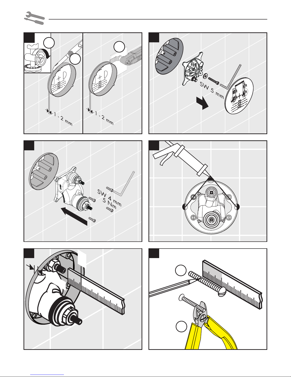
Installation Instructions
• The fitting must be installed, flushed and tested after
the valid norms!
• The plumbing codes applicable in the respective
countries must be oberserved.
• Prior to installation, inspect the product for transport
damages. After it has been installed, no transport or
surface damage will be honoured.
Technical Data
Operating pressure: max. 1 MPa
Recommended operating pressure: 0,1 - 0,5 MPa
Test pressure: 1,6 MPa
(1 MPa = 10 bar = 147 PSI)
Hot water temperature: max. 80°C
Recommended hot water temp.: max. 65°C
Thermal disinfection: max. 70°C / 4 min
Safety against backflow
The product is exclusively designed for drinking water!
English
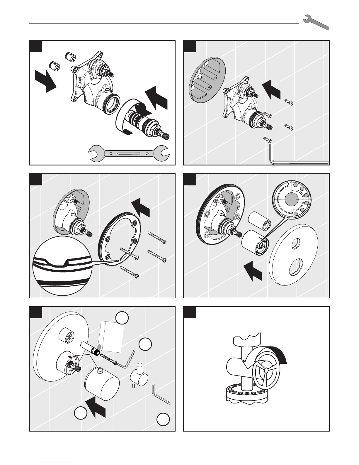
Maintenance (see page 64)
• To guarantee the smooth running of the
thermostat, it is necessary from time to
time to turn the thermostat from total hot
to total cold.
• The mixer is equipped with check valves.
The check valves must be checked
regularly according to DIN EN 1717 in
accordance with national or regional
regulations (at least once a year).
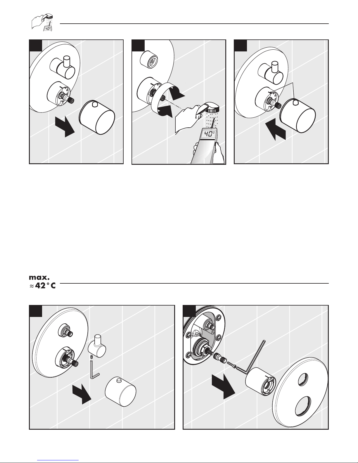
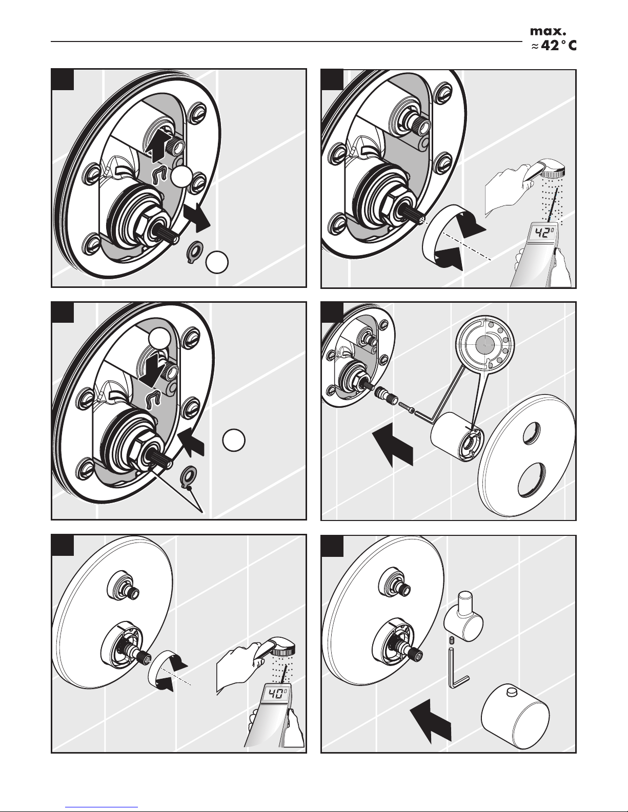
Adjustment (see page 62)
After the installation, the output tempera-
ture of the thermostat must be checked. A
correction is necessary if the temperature
measured at the output differs from the
temperature set on the thermostat.
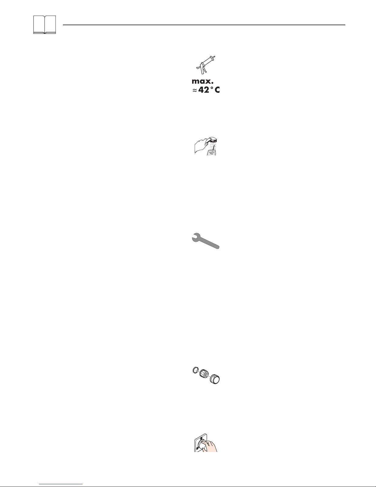
Safety Function (see page 62)
The desired maximum temperature for exam-
ple max. 42º C can be pre-set thanks to the
safety function.
Spare parts (see page 68)
XXX = Colors
000 = chrome plated
400 = white/chrome plated
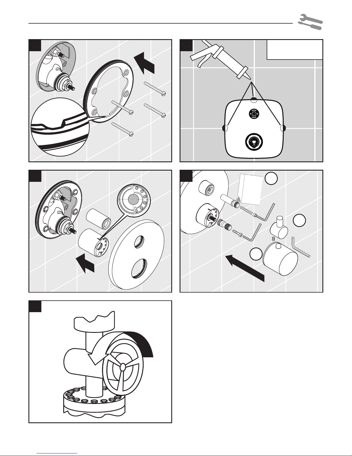
Do not use silicone containing acetic acid!
Symbol description
Operation (see page 66)
6

Flow diagram
(see page 67)
Test certificate (see page 66)Dimensions (see page 67)
English
Fault Cause Remedy
Insufficient water -Supply pressure inadequate -Check water pressure (If a pump
has been installed check to see if
the pump is working).
-Regulator filter dirty -Clean filter in front of the mixer
and on the MTC-thermo cartridge
-Shower filter seal dirty -Clean filter seal between shower
and hose
Crossflow, hot water being forced
into cold water pipe, or vice versa,
when mixer is closed
-Backflow preventers dirty or leaking -Clean backflow preventers, ex-
change if necessary
Spout temperature does not cor-
respond with temperature set
-Thermostat has not been adjusted -Adjust thermostat
-Hot water temperature too low -Increase hot water temperature to
42 ºC to 65 ºC
Temperature regulation not possible -Temperature regulator dirty or calci-
fied
-Clean temperature regulator, ex-
change if necessary
-For new installations: basic body in-
correctly connected (should be: cold
right, hot left) or installed with 180º
rotation
-Install function block turned
through 180º
Safety stop button not operating -Spring defective -Clean spring and/or button, ex-
change if necessary
-push button calcified / contaminated
Valve stiff -Shut-off unit damaged -Exchange shut-off unit
Shower or spout dripping -Dirt or sedimentation on valve seat,
shut-off unit damaged
-Clean or exchange shut-off unit
Assembly see page 60
Cleaning
see enclosed brochure
Special information for UK (see page 70)
7

60
Montage
3
2
4
1
2.
1. 2.
1.
2.
6 5
X
X + 11
1 - 2 mm

61
Montage
!
9
PuraVida
15775XXX
8
!
7
1.
2.
3.
Nr. 10476220
Armaturenfett
Grease
SW 2 mm
4 Nm
SW 3 mm
4 Nm
11
10

62
Safety Function
Justierung
1 2
SW 3 mm
!
1 2 3

63
Safety Function
2.
1.
5 6
SW 3 mm
4 Nm
78
z. B. 42° C
for example 42° C
1.
2.
3 4
SW 2 mm
4 Nm
!
!

64
Wartung
SW 4 mm
1. 2.
2
3 4
5 6
SW 24 mm
1.
2.
3.
1
SW 3 mm
SW 2 mm
4.

65
Wartung
!
SW 4 mm
5 Nm
7 8
9 10
11 12
SW 24 mm
15 Nm
Nr. 10476220
Armaturenfett
Grease
SW 3 mm
4 Nm
SW 2 mm
4 Nm
!
1.
2.
3.
4.

66
PA-IX DVGW SVGW ACS WRAS MCA ETA KIWA
15700000 PA-IX 9711/ID X X X X 1.43/18753 X
15701000 PA-IX 9711/ID X X X 1.43/18753 X
15775XXX PA-IX 9711/ID X X 1.43/18753 X
31572000 PA-IX 9711/ID X X 1.43/18753 X
DIN 4109
PA-IX 9711/ID
Bedienung
Prüfzeichen
>40° C
1.
2.
öffnen / ouvert / open / aperto / abierto / open / åbne /
abrir / otworzyć / otevřít / otvoriť / 开 / открыть /
nyitás / avaaminen / öppna / atidaryti / Otvaranje /
açmak / deschide / ανοικτό / odpreti / avage / atvērt /
otvoriti / åpne / отваряне / hape /
ﻞﻴﻐﺸﺘﻟا
ﺢﺘﻓ
قﻼﻏإ
ﻦﺧﺎﺳ
ﺎﺑدر
ﻒﻴﻈﻨﺘﻟا
Bedienung
öffnen
Schließen
Warm
Kalt
Reinigung
schließen / fermé / close / chiudere / cerrar /sluiten /
lukke / fechar / zamknąć / zavřít / uzavrieť / 关 /
закрыть / bezárás / sulkeminen / stänga / uždaryti /
Zatvaranje / kapatmak / închide / κλειστό / zapreti /
sulgege / aizvērt / zatvori / lukke / затваряне / mbylle /
ﻞﻴﻐﺸﺘﻟا
ﺢﺘﻓ
قﻼﻏإ
ﻦﺧﺎﺳ
ﺎﺑدر
ﻒﻴﻈﻨﺘﻟا
Bedienung
öffnen
Schließen
Warm
Kalt
Reinigung
warm / chaud / hot / caldo / caliente / warm / varmt /
quente / ciepła / teplá / teplá / 热 / горячая / meleg /
lämmin / varmt / karštas / Vruća voda / sıcak / cald /
ζεστό / toplo / kuum / karsts / topla / varm /
топло / i ngrohtë /
ﻞﻴﻐﺸﺘﻟا
ﺢﺘﻓ
قﻼﻏإ
ﻦﺧﺎﺳ
ﺎﺑدر
ﻒﻴﻈﻨﺘﻟا
Bedienung
öffnen
Schließen
Warm
Kalt
Reinigung
kalt / froid / cold / freddo / frío / koud / koldt / fria /
zimna / studená / studená / 冷 / холодная / hideg /
kylmä / kallt / šaltas / Hladno / soğuk / rece /
κρύο / mrzlo / külm / auksts / hladno / kaldt / студено /
i ftohtë /
ﻞﻴﻐﺸﺘﻟا
ﺢﺘﻓ
قﻼﻏإ
ﻦﺧﺎﺳ
ﺎﺑدر
ﻒﻴﻈﻨﺘﻟا
Bedienung
öffnen
Schließen
Warm
Kalt
Reinigung

67
Ecostat E 15700000 Ecostat S 15701000
PuraVida15775XXX Metris 31572000
Maße
Durchflussdiagramm

68
Serviceteile
13596000
(22 mm)
Ecostat E
15700000
94073000
96551000
96439000
94282000
94074000
96449000
96446000
94009000
96454000
(M5x55)
96447000
(Ø 165 mm)
95037000
96525000
(M5x20)
98133000
(16x2)
96451000
96435000
95508000
(48x3)
98371000
(29x3)
97669000
38391000
Ecostat S
15701000
97747000
13595000
(25 mm)
94073000
96551000
96439000
94282000
94074000
96449000
96446000
94009000
96454000
(M5x55)
96447000
(Ø 165 mm)
95037000
96525000
(M5x20)
98133000
(16x2)
96451000
96435000
95508000
(48x3)
98371000
(29x3)
97669000
36391000

69
Serviceteile
13597000
Metris
22 mm
15597000
PuraVida
22 mm
Metris
31572000
PuraVida
15775XXX
97747000
13595000
(25 mm)
94073000
95663000
96439000
94282000
94074000
96446000
94009000
96454000
(M5x55)
98793000
(Ø 145 mm)
95037000
96525000
(M5x20)
98133000
(16x2)
96451000
96435000
95508000
(48x3)
98371000
(29x3)
97669000
11791XXX
95356XXX
94073000
95904000
96439000
94282000
94074000
95356000
96446000
94009000
96454000
(M5x55)
98793000
(Ø 145 mm)
95037000
96525000
(M5x20)
98133000
(16x2)
96451000
96435000
98174000
(48x5)
98153000
(30x5)
97669000
95906000

70
Safety and Important Information
Hansgrohe products are safe provided they are installed,
used and maintained in accordance with these instructions
and recornrnendations.
Please read these instructions thoroughly and retain for
future use.
The plumbing installation of this thermostat mixing
valvemust comply with the requirements of UK
Water Regulations/Bylaws (Scotland), Building Regulati-
ons or any other regulations specified by the local Water
Authority and supplier.
The installation of thermostatic mixing valves must comply
with the requirements of the Water Supply (Water Fittings)
Regulations 1999.
We strongly recommend that you use a plumber registered
with or a member of an Association:
Chartered Institute of Plumbing and Heating Engineering
(CIPHE)
Water Industry Approved Plumber Scheme (WIAPS)
Dispose of plastic bags carefully
Keep children well away from the work area.
Check for hidden pipes and cables in the wall before
drilling holes.
The unit must be mounted on a finished waterproofed wall
surface (usually tiles).
If you are using power tools (e.g. to drill holes) wear sa-
fety glasses and always disconnect tools from the power
supply after use.
Do not operate the shower unit if the hand shower or spray
hose has been damaged or is blocked.
Do not block the flow of water from the hand shower, by
placing it on your hand or any other part of your body
or foreign object.
The thermostatic unit should be serviced annually by a
qualified person to ensure maximum safety during use.
The mixer is fitted with check valves (pages 68 and 69 pos.
94074000). There are filters on the thermostatic element
too (pages 68 and 69 pos. 94282000).
The fitting of isolation valves is required (preferred location
page 72 Installation Requirements)
On the following pages 69 - 74 you can
find important information only for the
installation in UK

71
Technical Data
This thermostatic valve will suit supplies of:
HIGH PRESSURE (HP-S)
Operating pressure: max. 10 bar
Recommended operating pressure: 1 - 5 bar
Test pressure: 16 bar
Hot water temperature: max. 80°C
Recommended hot water temp.: 65°C
Rate of flow: 26 l/min. @ 3 bar
Maximum outlet temperature: 43°C +/-*
Safety check: 40°C
Hot water connection: Left hand
Cold water connection: Right hand
Minimum difference between hot
water and mixed water temperature: 6 K
Hot and cold supply pressure should be balanced
Mixed water temperature
Application Mixed water temperature
(at point of discharge).
Shower 41°C max.
Washbasin 41°C max.
Bath (44°C fill) 44°C max.
Bath (46°C fill) 46°C max.
* For preset outlet temperature adjustment – See page 63.
NB. If a water supply is fed by gravity then the supply
pressure should be verified to ensure the conditions of use
are appropriate for the valve. Valves operating outside of
these supply conditions cannot be guaranteed to operate
as a TMV2 or TMV3 valve.
Recommended outlet temperatures
The BuildCert TMV scheme recommends the following
set maximum mixed water outlet temperatures for use in
all premises:
44°C for bath fill but see notes below;
41°C for showers;
41°C for washbasins.
The mixed water temperatures must never exceed 46°C.
The maximum mixed water temperature can be 2°C above
the recommended maximum set outlet temperatures.
Note: 46°C is the maximum mixed water temperature
from the bath tap. The maximum temperature takes account
of the allowable temperature tolerances inherent in thermo-
static mixing valves and temperature losses in metal baths.
It is not a safe bathing temperature for adults or children.
The British Burns Association recommends 37 to 37.5°C as
a comfortable bathing temperature for children. In premises
covered by the Care Standards Act 2000, the maximum
mixed water outlet temperature is 43°C
Installation Requirements
This thermostatic mixer valve must be installed in comp-
liance with current Water Regulations. If you have any
doubts about the Water Regulation requirements contact
your local water services provider or use the services of
a professional plumber.
This mixer valve is suitable for use with the following water
supply systems:
Gas Combination Boiler (multi-point) 1.0 - 10 bar*
Unvented System (pressure balanced) 1.0 - 10 bar
Pumped System 1.0 - 10 bar
IMPORTANT: If you install this mixer with a gravity fed
system, there must be a minimum head (vertical distance)
from the underside of tlie cold water storage tank to the
showerhead position of at least 5 metre.
Before connecting the mixer, water should be flushed
through the system to remove all debris that might otherwise
damage the valve.
*If pressure is in excess of 3.5 bar, a pressure-reducing
valve should be fitted.
Operating pressure range High pressure
Maximum static pressure - bar 10
Flow pressure, hot and cold - bar 1 to 5
Hot supply temperature - °C 52 to 65
Cold supply temperature - °C 5 to 20
Supply Conditions TMV2
Supply Conditions TMV3
Operating pressure range High pressure
Maximum static pressure - bar 10
Flow pressure, hot and cold - bar 0.5 to 5
Hot supply temperature - °C 55 to 65
Cold supply temperature - °C 5 to 25

72
KEY
Isolating valve
Reducing valve
Mixer Valve
Pump
Gas Combination Boiler (multi-point)
Unvented System (pressure balanced)
Pumped System

73
Table A: Guide to maximum stabilised tem-
peratures recorded during site tests
Application Mixed water
temperature
Shower 43°C
Washbasin 43°C
Bath (44°C fill) 46°C
Bath (46°C fill) 48°C
The mixed water temperature at terminal fitting should
never exceed 46ºC.
If there is a residual flow during the commissioning or
the annual verification (cold water supply isolation test),
then this is acceptable providing the temperature of the
water seeping from the valve is no more than 2°C above
the designated maximum mixed water outlet temperature
setting of the valve.
Temperature readings should be taken at the normal flow
rate after allowing for the system to stabilise.
The sensing part of the thermometer probe must be fully
submerged in the water that is to be tested.
Any TMV that has been adjusted or serviced must be
re-commissioned and re-tested in accordance with the
manufacturers' instructions.
Commissioning and in-service
tests
Commissioning
Purpose
Since the installed supply conditions are likely to be diffe-
rent from those applied in the laboratory tests it is appro-
priate, at commissioning, to carry out some simple checks
and tests on each mixing valve to provide a performance
reference point for future in-service tests.
Procedure
1. Check that:
a) the designation of the thermostatic mixing valve
matches the intended application
b) the supply pressures are within the range of ope-
rating pressures for the designation of the valve
c) the supply temperatures are within the range per-
mitted for the valve and by guidance information
on the prevention of legionella etc.
2. Adjust the temperature of the mixed water in accor-
dance with the manufacturer’s instructions (page 63)
and the requirement of the application and then carry
out the following sequence:
a) record the temperature of the hot and cold water
supplies
b) record the temperature of the mixed water at the
largest draw-off flow rate
c) record the temperature of the mixed water at a
smaller draw-off flow rate, which shall be measu-
red
d) isolate the cold water supply to the mixing valve
and monitor the mixed water temperature
e) record the maximum temperature achieved as a
result of (d) and the final stabilised temperature
NOTE: The final stabilised mixed water temperature
should not exceed the values in Table A.
f) record the equipment, thermometer etc. used for
the measurements

74
In-service tests
Purpose
The purpose of in-service tests is to regularly monitor and
record the performance of the thermostatic mixing valve.
Deterioration in performance can indicate the need for
service work on the valve and/ or the water supplies.
Procedure
1. Carry out the procedure 2. (a) to (e) on page 73
using the same measuring equipment, or equipment
to the same specifications.
2. If the mixed water temperature has changed signi-
ficantly from the previous test results (e.g. > 1 K),
record the change and before re-adjusting the mixed
water temperature check:
a) that any in-line or integral strainers are clean
b) any in-line or integral check valves or other
anti-backsiphonage devices are in good working
order
c) any isolating valves are fully open
3. With an acceptable mixed water temperature, com-
plete the procedure 2. (a) to (e) on page 73.
4. If at step 2. (e) on page 73 the final mixed water tem-
perature is greater than the values in Table A and / or
the maximum temperature exceeds the corresponding
value from the previous test results by more than about
2 K, the need for service work is indicated.
NOTE: In-service tests should be carried out with a
frequency which identifies a need for service work
before an unsafe water temperature can result. In
the absence of any other instruction or guidance, the
procedure described in „Frequency of in-service tests“
may be used.
Frequency of in-service tests
TMV3*
General
In the absence of any other instruction or guidance on
the means of determining the appropriate frequency of
in-service testing, the following procedure may be used:
1. 6 to 8 weeks after commissioning carry out the tests
given in 2. on page 73.
2. 12 to 15 weeks after commissioning carry out the tests
given in 2. on page 73.
3. Depending on the results of 1. and 4. several possi-
bilities exist:
a) If no significant changes (e.g. < 1 K) in mixed
water temperatures are recorded between com-
missioning and 1., or between commissioning and
4. the next in-service test can be deferred to 24
to 28 weeks after commissioning.
b) If small changes (e.g. 1 to 2 K) in mixed water
temperatures are recorded in only one of these pe-
riods, necessitating adjustment of the mixed water
temperature, then the next in-service test can be
deferred to 24 to 28 weeks after commissioning.
c) If small changes (e.g. 1 to 2 K) in mixed water
temperatures are recorded in both of these peri-
ods, necessitating adjustment of the mixed water
temperature, then the next in-service test should be
carried out at 18 to 21 weeks after commissioning.
d) If significant changes (e.g. > 2 K) in mixed water
temperatures are recorded in either of these
periods, necessitating service work, then the next
in-service test should be carried out at 18 to 21
weeks after commissioning.
4. The general principle to be observed after the first 2 or
3 in-service tests is that the intervals of future tests should
be set to those which previous tests have shown can be
achieved with no more than a small change in mixed
water temperature.
*TMV2: The frequency of performing the in-
service tests is 1 year maximum.

75
Thermostatic Adjustment
Temperature Limitation
The temperature is limited by the safety stop to 40°C. If
a higher temperature is required, it is possible to over ride
the safety stop by depressing the safety button.
NB. It is recommended that for private domestic
use the maximum mixed water temperature be set at the
following factory set values:
Shower Mixer 43°C
Bath/Shower 43°C
Temperatures can be set by following the procedures
on pages 62 and 63. This ensures that after correct
installation the outlet temperature of the water can never
exceed 43°C.
To guarantee a smooth running of the thermostatic element,
it is necessary from time to time to turn the thermostat from
total hot to total cold. The thermostatic mixer valve should
be checked annually by a qualified person to ensure
correct operation.
The mixer is fitted with check valves (pages 68 and
69 pos. 94074000) and filters (pages 68 and 69 pos
94282000). If the water flow drops the filters need to be
cleaned. For that purpose please follow the steps 1 - 12
on pages 64 and 65.
Calibrating Thermostat
If the temperature reading is different to the showering
temperature, follow the steps 1 - 3 on page 62.
Technical Hotline E-mail
0 870 7701975 Technical@hansgrohe.co.uk

76 Hansgrohe · Auestraße 5 - 9 · D-77761 Schiltach · Telefon +49 (0) 78 36/51-1282 · Telefax +49 (0) 7836/511440
E-Mail: info@hansgrohe.com · Internet: www.hansgrohe.com
06/2013
9.08420.08
This manual suits for next models
3
Table of contents