Hanshen TIG200P User manual

OPERATION
MANUAL
INVERTER DC PULSED
TUNGSTEN ARC WELDER
TIG200P
ATTENTION:
Be sure that all installation operation, maintenance and repair
procedures are preformed only by qualified individuals.
Read this operators manual completely before attempt to use
this equipment.
Save this manual and keep it well for quick reference pay more attention to the
safety instructions.

1
CATALOGUE
1. Characteristics & applications…………………………………….2
2. Safety attention……..……………………………………………...2
3. Range of welding parameters ……………………………………..4
4. Installing and connecting…… …………………………………....4
5. Prepare for welding………………………………………………..7
6. Weld-operating ………………….………………………………..10
7. Daily maintain & check…………………………………………...12
8. Trouble shoot…………………….…………………………….….12
9. Circuit diagram…………………….……………………………….16

2
1. CHARACTERISTICS & APPLICATIONS
This arc welder HT200P can invert the working frequency DC of 50Hz into the high frequency of
25KHZ, with built-in MOSFET from IR company and the application of PWM technique, and
reduces voltage, rectifies current and outputs a high DC power source fitting for welding. Its
functions include DC MMA, DC TIG welding and pulsed TIG welding.
Characteristics:
A. The output characteristics of welding are excellent and the welding current is calm.
B. Stability and dependability of the welder are much higher with application of contactless
circuit.
C. It is with rapid dynamic respond, calm arc, good welding line and nice welding
performance.
D. The functions are rich and its welding technology is good.
E. Arc igniting is stable and operation is easy with application of HF technique.
F. Its protection is perfect: with over-current and over-heat protection, slow startup of current
anti-strike.
G. The welder is much smaller, lighter and with high efficiency than ordinary welders.
Applications:
A: It can be used for welding all kinds of carbon steel, alloy steel, iron, stainless steel, copper,
titanium and their alloys.
B: it can be widely used in machinery industry, chemic industry, shipbuilding industry, vehicle
industry, decoration industry, etc.
2. SAFETY ATTENTION
A: Followi ng attenti ons should be observe d for safety guara n tee
(1).Confirm the followings such as supply power connected from your side, the spot for welder’s
installing, high-pressure gas, storage of workpiece and the treatment of rubbish according to your
national laws or your company’s standards.
(2).Dressing and safety protecting articles
In order to protect your eyes and skin, please wear the protecting articles according to your relevant
rules.
(3).On spot of welding

3
To avid from the injure and hurt by smoke and bad gas, the exhaust equipments ought to be
installed or useful breath apparatus should be used, depending on your rules. (4). Don’t open up
the welder or use it in open position.
B: Avoid burn i n g or fire
(1).Avoid burning from over-heat:
Keep the welder from the wall for more than 30cm and from combustible articles for more than
50cm.
(2). Avoid burning from spark
Keep spark far away from tinder or open holes.
(3). Avoid welder from impact or falling
Fasten the welder by fixed bolts.
(4). Don’t weld the tubes with gas or hermetic tubes and vessels.
(5). Don’t hang the torch on the gas bottle or touch the bottle with electrode.
C: Atten t ion while conn ectin g
(1). Only after disconnection of power and safety ensuring, the connection of welder can be
operated.
(2). Don’t touch the parts with electricity or wear the wet broken gloves.
(3). The cables should be selected according to the appointed standard.
(4). Don’t place the heavy on cables.
(5). The cables should be well connected and the bare electric parts ought to be well wrapped with
insulation.
(6). Only electrician with certificate can do grounding of welder or workpiece.
(7). The power of all equipments should be turned off while not using.
D: Atten t ion to HF
Arc of this welding machine is ignited by HF. To avoid electromagnetism hurt, we should:
(1). The welding cables should be shortened as possible.
(2). Place the cables nearly to the floor or ground with extending position.
(3). Place the cables of work-piece and cables of torch in parallel.
(4). The grounding of work-piece can’t be used together with other machines.

4
3. RANGE OF WELDING PARAMETERS
table 1. the range of welding parameters
TIG200P
TIG
MMA
Rated input voltage(V)
1-Phase,220V±10 %,50/60Hz
Rated input current(A)
17.5
Rated input capacity(KVA)
6.6
Rated output current(A)
200
160
Rated load voltage(V)
18
26.4
Idle voltage(V)
≤113
≤113
Rated duty cycle(%)
35
Crest current(A)
10~200
10~160
Base current(A)
8~200
/
Pulse frequency (Hz)
0.5~200
/
Pulse rate
0.1~0.9
/
Post flow time(s)
1~10
/
dimensions(W×D×H mm)
430×195×380
Weight(Kg)
18
4. INSTALLING & CONNECTING
(1).PO S ITION FOR USING
place the welder on the dry, clean and solid smooth ground.
The following spots are not allowed:
a. the place under the sunshine and rain.
b. the spot with dust, flammable gas or oil gas.
c. the spot with harmful or caustic gas.
d. the spot with high-humidity steam.
e. easy impacting spot.
f. The distance between each other less than 30cm.
g. the spot with surrounding temperature higher than +40℃ or less than -10℃.
Model
Parameter
Item

5
(2). GROUND I NG
Connect the welder’s grounding end with the grounding line of switchboard, or ensure the
grounding of input power cables connected with the grounding line of switchboard.
(3).VEN T ILA TI ON
Reduce the influence from wind as possible for ensuring the welding quality. But the enough
ventilation should be supplied for preventing the lack of oxygen ,when weld is operated in close
space.
(4).PO W ER SUPPL Y EQUIPM ENT & CON N ECTIO N S
table 2. power supply equipment & connections
mode
TIG200P
Input voltage(V)
1-phase,220±10%
Capability (KVA)
≥7.5
Input cable(m ㎡)
3*2.5
Output cable(m ㎡)
16
(5).GAS FO R WE L DING
The pure argon should be selected for welding quality and no gas leak after connection.
(6).CON N ECTI O N
a. Ensure the welder’s switch closed while connecting.
b. All tubes are in good position for preventing gas from leaking.
c. All bare wires should be wrapped with insulating tapes.
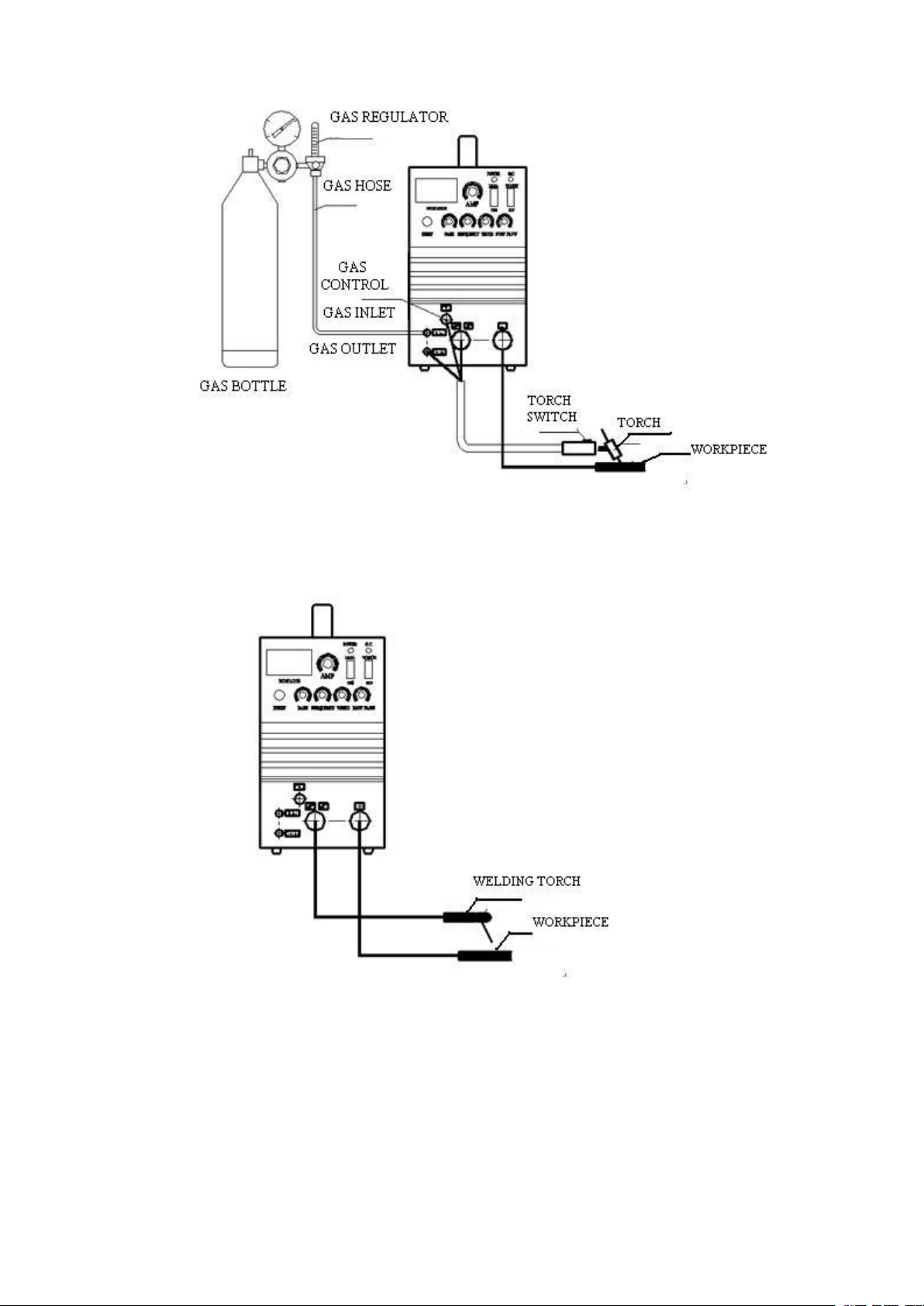
6
p i c t u r e 1 . c o n n e c t i o n f o r T I G w e l d i n g
p i c t u r e 2 . c o n n e c t i o n f o r M M A w e l d i n g
7
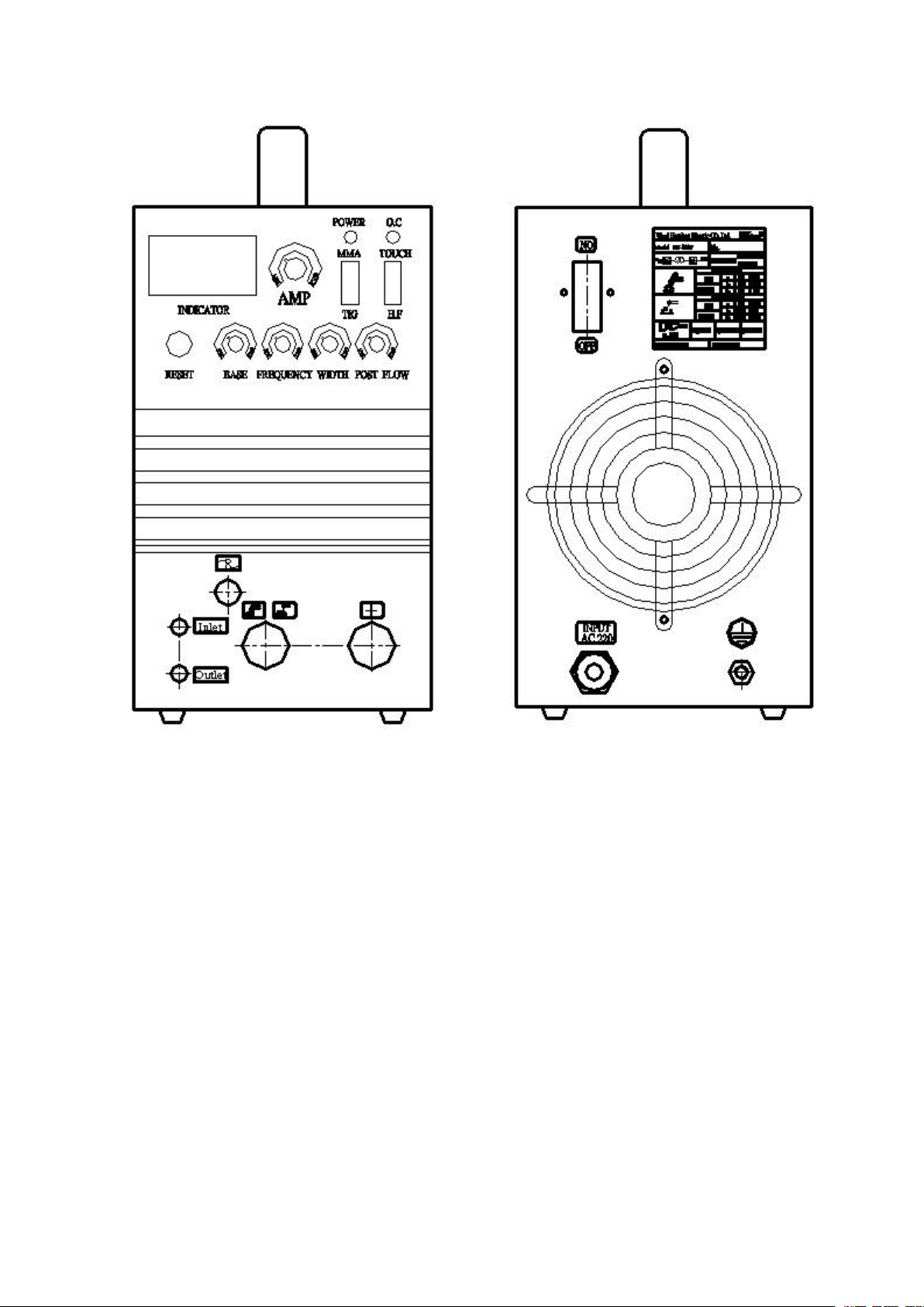
5. PREPARE FOR WELDING
p i c t u r e 3 F R O N T P A N E L p i c t u r e 4 R E A R P A N E L
(1).WELDER CONNECTION
Connect the welder according to the pictures1-3 and the requirements in 4.6 for welding.
ATTENTION: input voltage should be 1-phase, 220V.
(2).TUNGSTEN, PORCELAIN SPIGOT & ARGON FLUX
Select the proper tungsten, spigot and argon flux according to the lists 3-5 on the base of welding
material and its thickness.

8
List3、reference of tungsten
Current range
tungsten dia.
(mm)
Allowe d rang e of curren t(A)
Pu re tu n gsten
Th o rium tungs t en,
cerium tungst en
1. 0
10 ~80
10 ~80
1. 6
40 ~130
60 ~130
2. 0
75 ~160
10 0 ~160
2. 4
15 0 ~200
15 0 ~200
The end of tungst en oug ht to be sharp (ap pr ox im at el y 20 ° )in sm all curre nt.
The end of tungst en oug ht to be mill ed as a co ne wit h fl at ro of in lar ge cu rrent.
List4. welding parameter of stainless steel
Workpiece
thickness
(mm)
Tungsten
dia.
(mm)
Filling Wire
dia.
(mm)
Welding
current
(A)
Argon flux
(L/min.)
groove
condition
Nozzle dia.
(mm)
0.4
1.0~1.6
1.0
8~20
3~4
A or B
4~9 . 5
0.6
1.0~1.6
1.0
20~40
4~5
A or B
4~9 . 5
1.0
1.0~1.6
1.6
30~60
4~5
A or B
4~9 . 5
1.6
1.6~2 . 4
1.6
60~10 0
4~5
B
6~10
2.4
1.6~2.4
1.6~2.4
100~130
4~7
B
6~10
3.2
2.4~3 . 2
2.4~3 . 2
140~20 0
6~8
B
8~13
A B
P i c t u r e 5 . g r o o v e c o n d i t i o n
L i s t 5 . r e f e r e n c e f o r M M A
Stick dia.(mm)
2.0
2.5
3.2
4.0
Welding current(A)
30-60
50-100
80-160
120-200
9
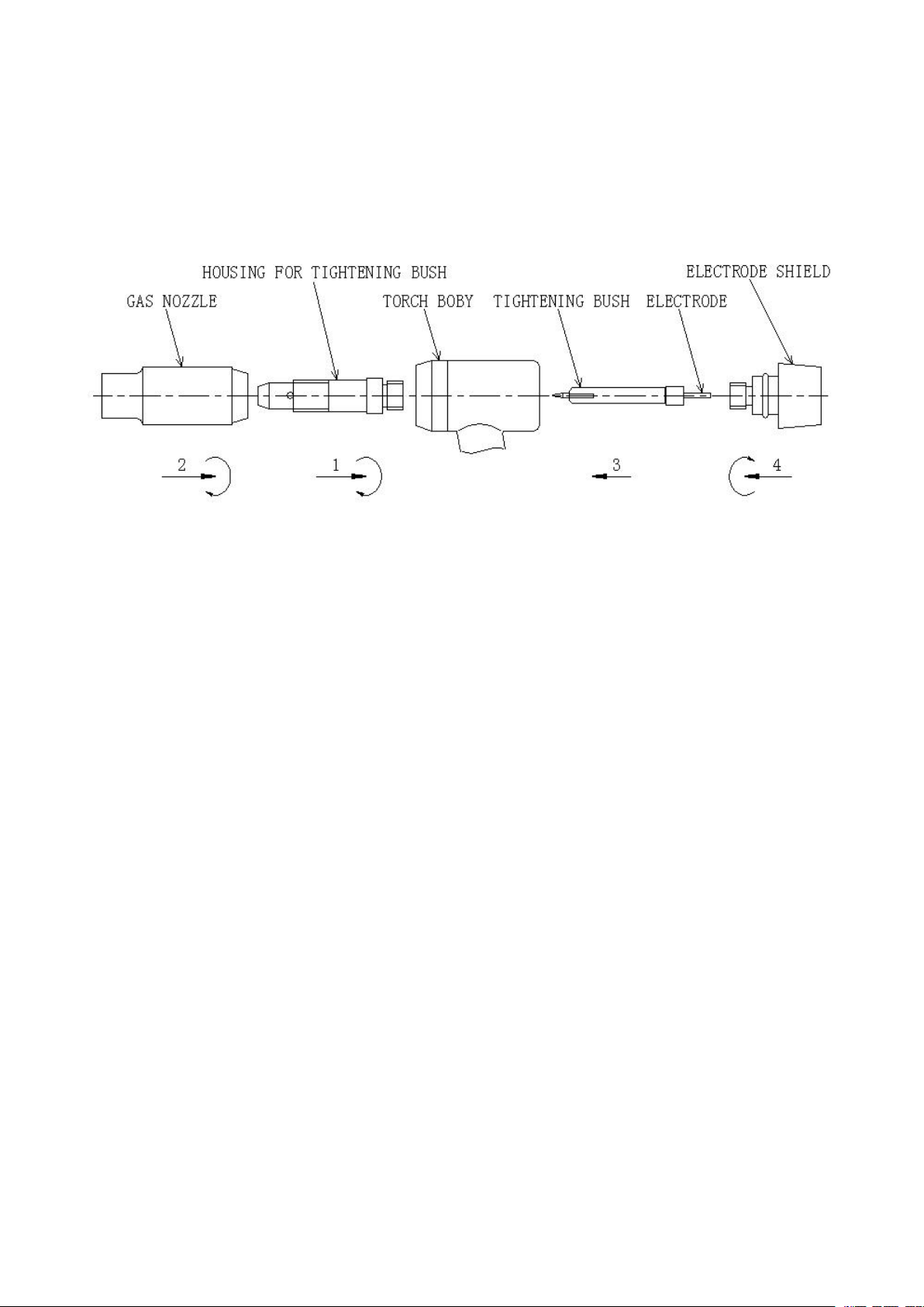
(3).TORCH
Instal l the torch acc o rding to list 5.
P i c t u r e 6 . s t r u c t u r e o f t o r c h
(4).WELDING MODE SELECTION & WELDING PARAMETERS
SETTING
Select the proper welding mode on the base of materials and its thickness, and set the proper
welding parameters referring to list3, 4, 5.
The details include:
a. Set the power-supply switch on the state of “power on”. When the power indicator turns light
and the fan runs, it means the machine has been normally started.
b. Selection of welding mode:
①MMA welding:
Turn the switch “MMA/TIG” to position “MMA”, and rotate the “base current” knob to the end
in clock-wise direction.
②AC TIG welding:
Turn the switch “MMA/TIG” to position “TIG”, and rotate the “base current” knob to the end in
clock-wise direction.
③Pulsed TIG welding:
Turn the switch “MMA/TIG” to position “TIG”, and adjust the “base current” knob in order to set
the current in a proper value less than summit current(“base current” is also named “stand-by

10
current”, it is always selected in a lesser value which can protect arc not breaking).
c. Open up the valve of argon bottle and adjust the flowmeter to the needed value.
d. Set post flow gas time:
Adjusting post flow gas time means that argon gas can be turned off later for a proper time after
welding being finished and arc being broken. It can more really protect the workpiece and guarantee
the quality of welding. The detail operation is: adjust the “post flow gas time” knob and select
needed value among 1-10 seconds according to the value of welding current (summit current).
Generally speaking, the bigger welding current or the higher welding quality is, the longer post
flow gas is; otherwise, the smaller or the lower is, the shorter is for saving gas.
The more the “post flow gas time” knob is rotated in clock-wise direction, the more post flow gas
time is increased.
6. WELDER OPERATING
MMA welding:
After all switches and knobs are checked in correct situation on the base of item 5.4, adjust “current
adjusting” knob according to thickness of workpiece, select the proper welding current and rods,
then begin to formally weld.
AC TIG welding:
a. According to item 5.4 check whether all switches and knobs are in correct situation.
b. After rotating the knob “base current” to the end in clock-wise direction, select the proper
welding current by adjusting knob “current adjust”.
c. Press the switch on torch and ignite arc by HF. The arc is automatically extinguished after
loosening the torch switch. The post-flow time can be adjusted among 1-10 seconds. Close
the argon bottle and turn off the welder after welding.

11
Pulsed TIG welding
P i c t u r e 7 . p u l s e r e l a t i o n
IP—summit current
Ib—base current
tp—width time of summit current
T—period of pulse
f=
T
1
,it can be adjusted among 0.5~200Hz.
D=
T
tp
,it can be adjusted among 0.1~0.9.
The bigger the pulse ratio is, the wider and deeper the welds are; otherwise, the narrower and less
deep.
The higher the pulse frequency is, the more dense the welding waves will become; otherwise, the
less dense.
Operation method:
The welds of a workpiece can be precisely controlled on the pulsed TIG welding mode, every
welding point can be heated up and cooled down quickly, the possibility of producing cracks can be
decreased. It is suitable for welding workpieces, which are of different heat conductivity and
thickness, and thin plates and ultra thin plates (of 0.4mm). As long as “base current” is kept below
“crest current”, the pulsed TIG welding effect can be achieved. A smaller volume of “base current”
(also referred to as “arc maintaining current”), is usually selected, as far as arc is maintained; the
selection of the pulse ratio (tp/T) depends on heat input, which is reflected on a weld’s width and
depth. 0.3 ~ 0.7 of the ratio is generally chosen. Pulse frequency is selected according to the
welding speed and the thickness of welding plates.
Apart from the above, operate the machine in the same way as on the AC TIG welding mode.

12
7. DAILY MAINTENANCE & EXAMINATION
Regular maintenance and examination can guarantee the machine in good work condition. When
the machine is not in use for a long time, it should be regularly and periodically (once two months)
examined in the state of electrification in order to ensure the machine dry and avoid the components
disabled or the parameters changed. The outer connections can be checked only after the power
supply is disconnected. Before inner circuitry and connections are checked, disconnect the power
supply and wait for 5 minutes for fully discharging from capacitor in machine in order to ensure
safety.
list 6: reference for examination
Item of circuitry examination
Regular examination for 1 or 2 months
1. Function of power switch
2. If the running of cooling fun is in normal
condition
3. If exists unwonted libration, noise or
smell
4. If the tie-in of welding cable is singularly
hot
5. If welding cable is singularly hot
6. If the cable is hurt
7. If all tie-ins of strikes are loose
1. Eliminate dirtiness
eliminate dirtiness by compressed air,
especially the dirtiness from reactor,
transformer, power transistor and PCB.
2. Examine the connections of electrocircuit:
Check the connections of input and output
sides, outer connecting lines, and screw
down the loose parts and eliminate rust to
guarantee the connections in good
condition.
3. Check if the grounding line is in good
condition.
4. Check the discharging clearance and make
it clean.

13
8.TROUBLES EXAMINATION & REPAIR
The overhauler can examine and repair the machine according to table 8 after examining it on the
base of list 7. Please contact the seller or the producer if the malfunctions still have not been
eliminated.
ATTENTION:
1. Because inner electrocircuit can produce high voltage which can hurt people, so before
maintenance and overhaul must turn off the switch in switchboard. Inner electrocircuit only can
be overhauled after 5 min. after power supply has been disconnected from welding machine.
2. The machine has been accurately adjusted before leaving from factory, so strictly prohibit any
modifying and change.
3. Check whether the circuitries are in correct connection. In order to avoid troubles do not
energize hard and change its position at will while connecting.
List7: overhauling items
Trouble phenomena
Trouble causes
No arc exists
Torch switch is useless
Power switch is broken
The cable to switch is disconnected
The cable to workpiece is disconnected
The cable of torch is broken
Starting arc is not good or jarless
Connecting tie-in is loose
Argon gas is not pure
The tungsten electrode is no good fixed or its
quality is no good
Surface of welding line is no good
Dunghill or grease exists on the surface of
workpiece
Argon gas is not pure
Flux of argon gas is not enough
Dunghill exists on the surface of tungsten
electrode
Post flow gas time is too short
Tungsten electrode wastes hard
Current is too great or tungsten electrode is too
thin
Argon gas is not pure

14
List 8
Troubles
Possible causes
Eliminate methods
Fun does not work after
turning on the power switch
Power does not exist
Check input power
Power switch is broken
Change power switch
Disconnection inside machine
Check inside connecting
The fun is broken
Change fun
Trouble of
arc-igniting
No voice of
HF
discharging
exists inside
machine
Torch switch or “arc control”
jack is broken or its
connection is no good
Check the condition of switch or
jack and its connection
220V/125V transformer is
disconnected or broken
Check transformer and its
connecting
Can not close J2(4123) relay
Check relay
High voltage box or capacitor
is broken
Check High voltage box or
capacitor
Voice of HF
discharging
exists inside
machine
Overheat protection or
overflow protection
Turn off the mcahine for a few
minutes and retry
Tungsten electrode is far
away from workpiece
Keep the distance of 2-3mm
between tungsten electrode and
workpiece
Tungsten electrode is not
sharp or is broken
Sharpen tungsten electrode
Tungsten electrode is bad
fixed or its quality is bad
Refix or change good tungsten
electrode
Welding current is too low or
workpiece is too dirty
Enlarge current or clean
workpiece
Discharging clearance of Arc
ignition unit is dirty
Clean clearance with sand paper
or alcohol
Output rapid diode is broken
Change diode
HF can not be turned off
Torch switch or arc control
wire is short- circuited
Check switch and jack
Relay J2(4123) in
AP-WSM(2) board is broken
Change relay J2(4123)
B3(339)in board AP1 is
broken
Change B3(339) or board AP1

15
Troubles
Possible causes
Eliminate methods
No argon flows out after
pressing the torch switch
Switch of argon bottle or
flowmeter doesn’t open up
Open up these two switches
Gas tube is jammed or broken
Check tube
Gas valve is broken
Change valve
Can’t close relay J3(4123) in
board AP1
Change relay J3(4123) or board
AP1
Can’t adjust welding current
Potentiometer for adjusting
current is broken or wire is
disconnected
Change potentiometer or
connect wire
B1 in board AP1 is broken
Change B1 or board AP1
Rated output current is
reduced
Input voltage is too low
Ensure the normal voltage
Input wire is too thin
Change power supply wire
Capability of power supply is not
enough
Ensure the capability of power
supply more than the maximal
power of machine in normal
work condition
Function “pulsed TIG
welding” does not exist
One of the base current, summit
current or pulse frequency
potentiometers is broken
Check and change the broken
potentiometers
M1(4011),N1(555),B1(339) in
board AP1 is broken
Change M1(4011),N1(555),
B1(339) or board AP1
Inverter tube (IGBT) is
broken
Work in over loading condition
for a long time
Change IGBT
Work in over voltage or under
voltage condition for a long time
Change IGBT and ensure the
normal input voltage
Output commutation diode
is broken
Work in great current condition
for a long time or environment
temperature is too high
Change broken diode and
improve work condition
Frequent burnout of diode is
caused by the large discharging
space of arc-igniting unit.
Adjust the discharging space to
1.0-1.2mm

16
9. CIRCUIT DIAGRAM
Table of contents
Other Hanshen Welding System manuals


Popular Welding System manuals by other brands


WELDKAR
WELDKAR WK TIG 2025 AC/DC Pulse instruction manual

Chicago Electric
Chicago Electric 62719 Owner's manual & safety instructions

Lincoln Electric
Lincoln Electric PRECISION TIG 375 IM909 Operator's manual

Leister
Leister HEMTEK ST operating instructions

Sealey
Sealey SUPERMIG230 instruction manual

Munsch
Munsch GM-50-FU operating instructions


