Hanshen HP80 Series User manual

0
OPERATION
MANUAL
IGBT INVERTER AIR PLASMA
CUTTING MACHINE
HP80/120/200 SERIES
ATTENTION
For safety guarantee,only the person with operating certificate or
expert skills can collocate,check,maintain,fix and repair the welder.
For safety guarantee,please completely read and understand the ditails
in this manual before using.
Keep the manual in convenient place for easy reading.

1
CATALOGUE
1、 CHARACTERISTICS &APPLICATIONS………………………2
2、 SAFETY ATTENTION …………………………………………3
3、 TECHNICAL PARAMETER……………………………………4
4、 INSTALLING&CONNECTION…………………………………5
5、 PREPARE FOR CUTTING……………………………………11
6、 DAILY MAINTAIN&CHECK…………………………………14
7、 FAULT REPAIR………………………………………………15
8、 CIRCUIT DIAGRAM……………………………………………18

2
1、 CHARACTERISTICS &APPLICATIONS
HP air plasma cutting machine series,can invert the working frequency DC of 50Hz into the
high frequency of 20KHz,with IGBT and soft switch technology,the application of PWM
technique,and reduce voltage,rectifies current and output a high DC power source and suitable
for cutting .The character is as follows:
The machine is projected by adopting entire-bridge inverter technique and with IGBT
elements.
1.Inverter frequency is above 20KHz by adopting PWM technique.
2.Can preset and continuous adjust the current ,suitable for different thickness work piece ,make
sure cutting quality and save energy.
3.Arc ignition of cutting machine is adopted with small flow of air and HF transfer arc method
for 100% arc ignition..
4.With over-heat 、over-current and arc starting protection.
Suitable for application
Such as carbon steel,alloy steel,nonferrous metals etc.
For operation in machinery industy,petroleum industry,ship building industry,vehicle
industry,electricity industry and decoration.

3
2、SAFETY ATTENTION
2.1 Avoid body event to assure safety operate obey the following
point:
a.The power item of input side、the location choosing、high-pressure gas use 、store and
supply ,welding products store and trash handling etc.please follow related laws or enterprise
standard.
b.Clothing wear and safty tools equip.To avoid eye inflammation and skin burn,please obey
related safty and healthy regulation ,please wear related protecting tools.
c. To avoid noxious gas and stifled(the welding soot and CO2 are harmful to body),must obey
related regulation regarding the soot handling.Installing partial exhausting equipment or use
effective breathing protecting equipment.
d. Can not operate without the weiding machine cover.
2.2 Avoid machine burning and fire
a. Avoid fire because of overheated, please keep 50cm distance between welding power and
the wall or combustibles.
b.Avoid fire because of spark.Forbid spark to touch the combustibles or enter the inspiration、
any open part of welding machine.
c.Avoid damaged by falling or break.During assemble welding machine in frame,to assure
security and avoid slipping ,please fasten the welding machine first.
d. Forbid to have gas piper or any seal can and pipe inside the welding machine.
2.3 Electric connecting item
a. Before connecting operating must turn off power and assure safty.
b. Forbid touch electric part or touch with wet glove.
c. Choose correct line type.
d. Avoid heavy touch on line and touch welding part.
e. Connect the line joint well,use insulating tape around bare wire.
f. Handle ground connection between machine cover and workpiece holder by professional
worker.
g. turn off power after finish welding.

4
3、 TECHNICAL PARAMETER
Table1、tec hni cal par ame ter
Model
Data
HP80
HP120
HP200
Rated input voltage(V)
3-Phase 50Hz
380
Rated input current(A)
14
26
54
Open voltage(V)
250
325
345
Range for cutting current (A)
30-80
30-120
30-200
Rated duty cycle(%)
Best cutting thicken
(carbon steel mm)
18
25
45
Max.cutting thickness
(carbon steel mm)
32
45
65
Shell protection degree
IP21S
Insulated class
F
Dimension(D×W×H mm)
640*335*670
690*335*670
700*350*660
Weight(Kg)
50
56
65

5
4、 INSTALLING&CONNECTION
4.1 Operate situation
Welding machine must put on flat 、cleaning and dry ground .Forbid to put the welding
machine on following situation:
a.Under hard sunshine and raining place.
b.With dusty and combustible gas place .
c.With harmful or caustic gas place.
d.With high temperature and steam place
e.Vibration and collision place.
f.The distance between other circumambience smaller than 50cm.
g.The temperature higher than +40℃or less than -10℃..
4.2 Ground connecting
Connect the machine’s ground connecting port to power’s ground connecting port and avoid
damaged by electric shock.
4.3 Ventilation
To assure welding quality must reduce the wind influence.If operate in seal space should
supply aeration equipmennt and avoid lack of oxygen.
4.4 Power and line
Table2、power and line (only for reference)
Model
HP80
HP120
HP200
Input power
3-Phase,AC 380V/ 50Hz
Capacity
Power
Above 14KVA
Above 26KVA
Above 26KVA
Engine
Two times than
14KVA
Two times than
26KVA
Two times than
26KVA
Input
protect
equipment
Fuse
30A
55A
55A
Leak
electricity
safeguard
machine
30A
55A
55A
Input cable(mm2)
≥6 mm2
≥10 mm2
≥10 mm2
Output cable(mm2)
≥16 mm2
≥25 mm2
≥25 mm2
Ground cable(mm2)
≥14 mm2
≥14 mm2
≥14 mm2
6
4.5 Connecting
a.The connecting must according to the table 2 requirement.
b.Turn off the cutting machine before connecting cable.
c.All joint must connect well ,use insulating tape around bare wire.
d.After connecting,put power cable cover on machine ,then fasten with screw(forbid to
operate with cover open)
e.To assure security forbid to input force on the cable.
(FIG.1)HP63 connecting diagram

7
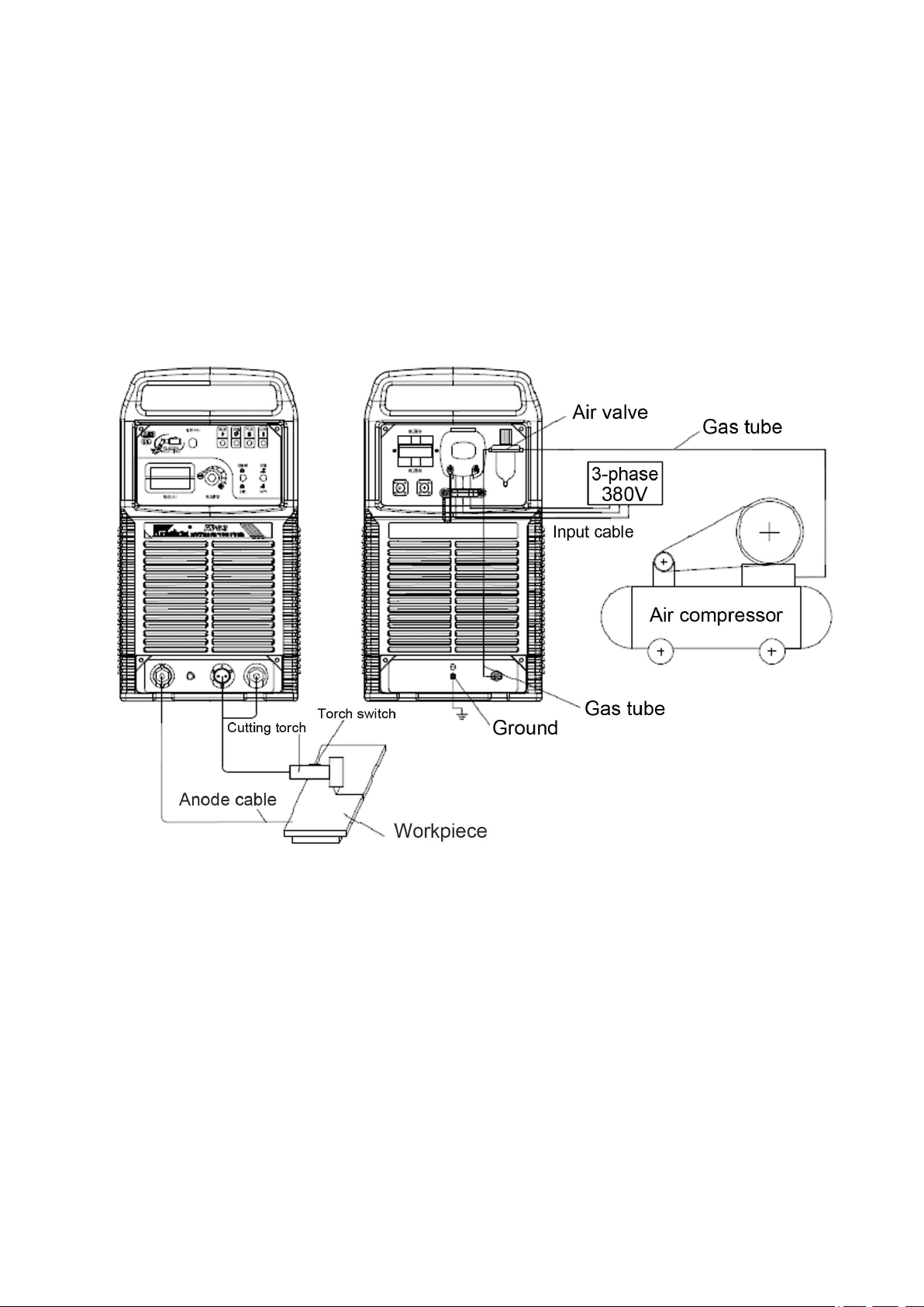
(FIG.2)HP80/120 connecting diagram

8
(FIG.3)HP200 connecting diagram

9
4.6 Front and back panel
电源关
电源开
1
2
3
4
5
6
7
8
9
10
11
12
13
14
15
16
17
18
19
20
21
(FIG.4)front and bank panel for HP63/HP80 /HP120
神
回水 水
电
接
口
口
接
电
气
电流调节
水冷
气冷试气
切割
自锁
非自锁
水压气压 过热切割电源
A
( )
电流
电源
( )
2A
2
2
0
I
U
X
eff
1
1
1max
~
~f
1
2
f
防护等级: 绝缘等级:
制造商:无锡汉神电气有限公司
生产厂:无锡汉神电气有限公司
地 址:江苏省无锡市锡山经济开发区芙蓉一路以北
R
IP21S F
进气
回水进水
电源关
电源开
① (+)
①②
⑥⑦
② (-)
割炬开关
起弧成功
IG B T 逆变式空气等离子切割机
引弧接口 -
+
R
汉
20
27
22
23
25
24
12111091
28
21
15
17
16
26
14
13
19
8
7
6
5
3
2
FUSE
18
(FIG.5)front and back panel for HP200

10
Table.3 Function
NO
Name
Function
1
Fuse
When short circuit,the fuse welt to protect control transformer
2
Current
Adjust cutting current
3
Digital meter
Indicate preset current when machine stand by,indicate welding current when
cutting
4
Torch(-)
Power cathode,to connect the tie-in of water cooling torch
5
Torch switch
Joint torch control connector
6
Starting arc
Connect torch starting arc line(HP63 has no this function)
7
Workpiece(+)
Power anode ,joint workpiece
8
Air switch
Automatic to turn off power when machine overload or get wrong,normally
this switch need to be turn on
9
Power
Power indicator,when cutting machine turn on ,the indicator will be light
10
Cutting
Cutting indicator ,will be linght when cutting torch turn on
11
Air pressure
Air pressure indicator ,when low than 0.2Mpa,cutting machine will stop work
12
Over-heat
Over-heat indicator ,when cutting machine is over-heat ,they can not work
13
Lock/Unlock
Transfor switch,when in“lock”,press torch switch to ignite arc ,can loosen
switch,cutting machine still go on cutting ,if press the torch switch
again ,cutting will stop
14
Air test/Cutting
When turn on air test,gas valve in cutting machine will be opened to check
gas flow rate,when turn on cutting,gas valve will be automaticly open and
supply gas when machine is cutting
15
Power box
Connect input cable
16
Control sign
Automaticly connect with cutting machine①② : torch switch ; ⑥⑦ :
successful to ignite arc
17
Output arc
Automaticly connect with cutting machine①:+,②:-
18
Fixed clamp
Fixed input cable
19
Air pressure
regulator
Adjust pressure of compressed air and to filter water in the air
20
Inlet of compressed
air
Connet gas tube and air pressure regulator to supply gas for cutting machine
21
Ground screw bolt
In order to make sure safety ,please ground connection with this screw bolt
22
Hydroelectric
interface
Power output (-),be used for connecting with Hydroelectric interface of
water –cooling cutting torch
23
Gas electric
interface
Power output(-),be used for connecting with gas electric interface of air-
cooling cutting torch or inlet connection of water- cooling cutting torch
24
Water pressure
Indicator of water pressure flow will be light when water pressure is
lower,and cutting machine will stop work.
25
Water return
Used for conecting with water return pipe’s lead arc of water-cooling cutting
torch
26
Water cooling/Air
cooling
According with cooling type of your cutting torch to chose corresponding
switch,when is “water-cooling”,if chose “water-cooling”torch need to make
sure under “water-cooling”condition,otherwise the cutting torch will be
damaged.
27
Water inlet
To link through water pipe and water outlet.
28
Water return
To link through water pipe and water return.

11
5、 PREPARE FOR CUTTING
5.1 Connect cutting machine
According with 4.5and FIG1、FIG 2、FIG 3 to connect with cutting machine
5.2 Cuttin g oper a ti o n
a. Turn on the power source ,cooling fan will be work as usual.
b. Turn on gas switch and put the switch to “air test”,then rotate air pressure regulator to chose
suitable gas flow rate.If air pressure low than0.2Mpa ,cutting machine will stop work,if
everything is ok, air pressure light will turn off,please put “air test/cutting “switch to
“cutting”at the same time.
Note:air pressure≥0.45~0.6MPa,flow rate ≥300L/min。
c. This cutting machine standard collocation adopt non-contact cutting torch.When cutting
machine ,nozzle will not meet workpiece due to if they get to each other, it’s easy to damage
electrode and nozzle. At this time,in order to control cutting torch height, we usually match
series of cutting tool、photoelectric follow up 、robot and CNC cutting machine tool.
Operation points as following:
a) Trolly the cutting torch to meet workpiece,and keep distance 2-5mm,make sure nozzle
axes apeak to surface of workpiece and don’t touch.( FIG6)
b) Turn on cutting switch ,ignite plasma arc ,cutting workpiece fully ,keep an even speed to
move along with cutting direction,Cutting speed is :base on cutting pierce,be fit for rapid
to cut ,if too slow will affect cutting quality even arc break off. Please control towing
angle in 10°(F6), cutting quality is perfect,if too fast won’t pierce,even spatter.
c) Generally speaking cutting from the edge of workpiece,when need to cut from the middle
of workpiece,if material thickness is≤5mm(stainless steel or carton steel,if other
material,need to cut back on cutting thickness),can directly cutting pierce.Method:put
cutting torch on starting point of cutting sew,make nozzle and workpiece an included
angle about 75°,then turn on torch switch,ignite arc to pierce workpiece,adjust torch axes
to apeak workpiece.But if material thickness≥5mm and need to cut in middle,please drill a
hole which diameter is ≥3mm,ignite arc to cut in hole.
d) If finish cutting ,unlock torch switch,break off plasma arc.compress air will be delayed
spurt to cooling cutting torch.After some minutes please move torch to finish cutting.

12
(FIG.6)cutting diagram
5.3 Cutting torch for installing、maintenance and replacement
Note:Before starting,please put the switch to“power off”on the machine.
(1)Installing cutting torch please reference FIG7.Plesae note must sure electrode is
tightened by spanner.
(2)Please replace nozzle on time when centre hole of nozzle is damaged(F8)
(3)Please replace electrode on time when electrode hafnium is damaged (F9)
(FIG.7)installing diagram

13
(FIG.8)nozzle burned diagram
(FIG.9)electrode burned diagram
(4)When gas tube、shield cap、cable is damaged,need to replace on time
(5)When you need dismantle the cutting torch,please demount bolt M3,then insulated
pipe ,at last is connect and transfer arc. When installing ,please take care every joint and
insulated pipe to make sure safety in igniting arc.
(6)Cutting torch and cable team can not touch high temperature workpiece.

14
6、DAILY MAINTAIN&CHECK
Safety warm:Before maintaining ,must cut off the power to avoid to be injured such aselectric
shock and burned,and please wait for 10 minutes then start to repair.
Table4 reference for maintain
ITEM
EVERY ONE OR TWO MONTH TO CHECK
AND MAINTAIN
1.Switch function for power
2.Cooling fan if is working
normally
3.If have unusual vibrate、noise
and smell
4.If cable connector is over-heat
5.Welding cable if is over-heat
6.Cable if is damaged
7.All cable connector if is loosen
1.Remove smudginess:
Make use compressed air to remove
smudginess,especially for inductance 、
transformer、transistor and PCB.
2.Repair for circuit diagram:
Check input ports ,output ports and exterior
cable
3.Check earth cable if is all right.

15
7、FAULT REPAIR
Inspector can check the machine follow table 5,and repair follow table 6.If the failure can not
be eliminated,please contact with manufactory.
ATTENTION:
1.Before the maintenance or repair,make sure the power is off to avoid electric shock.
2.The machine has tested before leaving factory,any modification is not be allowed.
3.During the inspection of wire connecting ,please don’t pull hard and change any connecting.
Table 5 Inspection item
Failure
Causing
Can not ignite arc
Power switch damaged or switch wire broken
The cable which connect with workpiece is
damaged ,or the clamp cable is damaged
Input power lack phase
Over loading,over heating or over current
protection
Input power cable loosing
Output cable connector loosing
Compressed air pressure is too low
Arc is unstable,or arc break frequently
Output cable connector loosing
Input power cable with bad connection
Decrease of output current
Input power is not between 330V~440V
Input power cable is too thin
Power capacity is low

16
Table 6 Inspection item
NO.
Failure
Causing
Solution
1
Turn on power,but
power indicator light
does not work
1、Indicator light damaged
Change
2、2A fuse damaged
Change
3、No input power
Repair
4、Lack of input powe
Repair
5、Power switch damaged
Change
6、Control PCB damaged
Repair
7、Control transformer
damaged
Repair
2
Switch on,power
indicator is light ,but the
fan does not work
1、Fan get stuck something
Eliminate the something
2、Fan capacity damaged
Change
3、Fan wire damaged
Repair
4、Fan is broken
Change or Repair
3
Switch on,power
indicator light on,fan
works,turn on the “air
test”,but no air flow
1、No input compressed air
Check air source and air pipe
2、“Adjusting air pressure
filter”error,pressure meter
shows zero,“air pressure
lack”indicator linght on
Readjust the air pressure
filter,method:turn “air
pressure filter”clockwise to
increase the pressure ,turn
anti-clockwise to decrease.
3、“Air test”switch damaged
Change
4、Main electromagnetism
valve
Repair or change
5、Air hose break or leak
Repair
4
Turn on “air
test”,nozzle fill with air,
turn on “cutting”,and
turn on the cutting
torch ,there is no air
1、Torch switch damaged or
switch wire damaged
Repair or change
2、Air valve QF1damaged
Change
3、Control PCB damaged
Repair
5
Turn on the cutting
torch,nozzle with
air .but torch does not
work
1、Input power lack phase
Repair
2、Input air flow is zero
Increase input air flow
3、Nozzle、electrode or
other parts damaged
Change
4、Torch damaged
Change
6
Kerf deflexion
1、Nozzle or electrode
damaged
Change
2、Nozzle and electrode does
not install correctly
Reinstalling
3、Cutting speed is too fast
Reduce cutting speed
4、Nozzle and cutting
material is out of the vertical
Adjusting

17
NO.
Failure
Causing
Solution
7
Setting cutting
thickness cannot be
achieved
1、Input voltage cannot get to
rated voltage
Inputting voltage
2、Input power supply capacity is
toosmall and cutting line
preesure is too big
Increase input power supply
capacity
3、Input compressure air pressure
is too low or too high
Adjusting the air pressure
4、Input air flow is too small,such
as preesure meter drops to
0.3Mpa during the
operation ,and pressure recover
after stop working
Increase the compressed air
flow to 300L/min;If the air
hose is small ,please change
the hosediameter to more
thanΦ8mm
5、Cutting speed is too fast
Reduce cutting speed
6、Nozzle burned
Change
7、Electrode has burned
Change
8、Nozzle size is not fitted
Change to the right size
9、Air hose or cutting cable
damaged
Repair or change
8
Kerf with wide
incision and poor
quality
1、Cutting speed is too slow
Adjusting speed
2、Nozzle and electrode burned
Change
3、material、thickness and option
of thickness have wrong position
Adjusting
4、Nozzle type is wrong and
diameter is too big
Change a right size one
9
Torch burned
1、Nozzle or electrode loosing
Fasten the nozzle or
electrode
2、Torch wire connector
loosing ,or cable /hose
damaged
Check on time
3、Torch connrctor with poor
insulation condition
Make sure the torch
connector with good
insulation
4、Shield cap of cutting torch has
been damaged
Change on time
5、Compressed air is over wet
Clear the water in “air
pressurevalve”,if the air wae
over wet ,please install
water flilter Lv1~2
6、Electrode burned
Change a new one

18
8、DIAGRAM CIRCUIT
Q F1
CN 13
97 97
105
87
86
50
52
51
52
52
50
51 3
2
1
4
3
2
1
97
731
2
CN 12
1
2
397
56
72
80
97
98
96
2
1
3
2
1
2
3
4
3
2
1
97
65
20
CN 9
CN 14CN 15
CN 3
CN 10
W
1
V
2
U
71
0. 25m H
70
~
~
~
BR1
RY 4
Q 3
C1- 9
C8
C2, 3
RY 1
RY 3
RY 2
S 1
C1
TV S1
8 4
8 5
Q 4 C10- 18
TV S2
8 6
8 7
Q 1
TV S1
8 0
8 1
Q 2
TV S2
8 2
8 3
L3
+
-
8 7
8 6
~ ~
FU SE
C8
TS
S4
68
67
66
1
2
3
CN 8 97
59
20
61
60
1
2
4
3
5
CN 6
CN 1
M1
~10 V
6
7
8
9
1
3
CT 1
380V
220V
0V
T1
FS
FH 7.8 20 .4 1 3
R1,2,3,4,5
L1
L2
B
A
R3
R4 R4
R3
97
96
1
3
2
3
4
5
97
2
1
CN 9
CN 10
CN 11
CN 8
85
84
8 5
8 4
1
3
CN 6
83
82
8 3
8 2
1
3
CN 4
81
80
8 1
8 0
1
3
CN 2
~19 V
~19 V
1
98 2
2
2
2
2
D 1
D 2
D 3
D 4
A
B
H GQ
R1
R2
R1
R2
~16 V
~16 V
~16 V
~16 V
~16 V
~16 V
~16 V
~16 V
94
95
1
3
CN 7
87 2
92
93
1
3
CN 5
85 2
90
91
1
3
CN 3
83 2
88
89
1
3
CN 1
81 2
TR1
C6 C7
CT 3
6T
993
105
1
101
102
97
106
100
104
103
97
97
64
63
97
1
2
4
3
5
CN 5
662
RP 1
4K 7
55
54 1
2
C9 C10
J1 J1-1
TR 2
57
97
1
2
CN 2
S3
+15V
-15V
OUT
GND
LE M
检气
焊接
自锁
非自锁
CN 11
2
3
1
T2
~24V
0V
380V
D1
D2
+'
50
R6
50
R7
50
R8
50
R9
C1 C2
C1 C2
100
R3
100
R4
100
R5
KM 1 -1
C7
C7 C6
2
R1
2
R2 R3 C 3 C 4
C1
C2
C5
2
R4
X1
X2 X3X4
X5
FH7.820.416
C
D
21
0V
110V
CN 4
QF2
KM 1
25V
S2
2
1
FH7.820.412
C
D
3 69
97
59
20
61
60
1
2
4
3
5
CN 1
586
切 割
气 压 水 压过 热
电 源
58 6
FH7.820.418
S5
7
气压开关
CN 7
200
201
FH7.820.296
50
R1
50
R2
FH7.820.294
FH7.820.323
FH7.820.327
FH7.820.327
H C- II- AP 2
H P -A P1
H P -A P2
H P -A P5
H P -A P4
H C- II- AP 8
H C- II- AP 8
HC-II-AP5
H C- II- AP 3
R 1 -2R 1 -1
FH4.702.051
FH4.702.048
-
+
1 2 3
1
2
3
4
5
6
7
115
116
115
116
115
116
71
69
TS
O K
This manual suits for next models
2
Table of contents
Other Hanshen Welding System manuals


Popular Welding System manuals by other brands


Miller
Miller Summit Arc 1000 owner's manual

Baileigh
Baileigh WP-1800F Operator's manual

FRONIUS
FRONIUS TransSteel 3500 Syn operating instructions

Telwin
Telwin TECNICA 190 TIG-MMA DC LIFT VRD manual

widos
widos 4000 WM Working Instructions Translation

CEVIK PRO
CEVIK PRO CE-TITANCEL 210 instruction manual


