Hanshen HC350D User manual

OPERATION
MANUAL
IGBT INVERTER MULTIFUNCTION
WELDING MACHINE
HC350D/500D/650D
ATTENTION:
Be sure that all installation operation, maintenance and repair are
performed only by qualified personnel.
You are advised to read this operation manual thoroughly before using
the equipment. Keep this manual for future reference and safety
information.

-1-
CONTENT
1. Characteristics…………………………………………………...2
2. Safety ……………………………………………………………3
3. Technical parameters ……………………………………………4
4. Installation and connection………………………………………5
5. Function introduction……………………………………………9
6. Operation………………………………………………………..12
7. Daily maintenance and trouble shooting ……………………….16
8. Circuit diagram………………………………………………….18

-2-
1、CHARACTERISTICS
HC-D series welding machine have CO2 and MMA function (if make use
appointed welding torch, also can bring about simple TIG function). HC-D
series machine can be used widely in various fields. Its characteristics are as
following:
1.1 With high quality for welding
Adopted high-quality and advanced control circuit, with good dynamic
response, and it can easier achieve nice-looking weld slot.
1.2 With obvious electricity saving
Adopted inverter technology and voltage equalization, can deeply reduces
the input capacity, meanwhile saving electricity.
1.3 With presetting function
The welding current and voltage can be preset in advance, and it is easy to
be read via digital display meter. It is more useful for beginner.
1.4 With lighter weight and smaller dimension
Compared with rectifier/thyristor model welding machine, HC-D series
machine 1/3 of rectifier machine, and its weight is 1/4 of rectifier machine.
So it is more convenient for outside working.
1.5 With less splash
With wave-form control technique, the splash while welding is deeply
reduced. and suitable for welding from all position.
1.6 With high ratio of arc ignition
The arc ignition ratio can be reached 100% via special ignition circuit.
1.7 For MMA usage
The arc-ignition current can be adjusted while welding, and the welding
rod is not easy to be agglutinated with workpiece. With arc force circuit
design, the arc characteristics can be adjusted according to welding
technology. The welding is stable and with less splash.
1.8 With stable welding process
Adopt high-speed feedback circuit,welding system can be anti-interference
and resistance network fluctuation,thus realize the stable welding process

-3-
2、SAFETY
Please observe the following safety information for your own safety:
2.1 Avoidance of accident
A. Ensure that you operate the equipment with the power source of correct
voltage as provided by your country;
B. Ensure that you comply with the laws of your country on position for
welder’s installation, high-pressure gas, storage of materials and
treatment of rubbish…etc;
C. Ensure that you wear the safety equipment and dress for the protection
of your eyes and skin;
D. Ensure that there is proper ventilation on place of welding to prevent
injury or hurt by smoke and gas exhaustion;
E. Do not open the DOS shell of the welder or use it in open position.
2.2 Prevention from burn and fire
A. Always keep the welder with a distance 30cm away from the wall and
50cm away from any combustible articles;
B. Keep sparks away from tinder or the open holes;
C. Fasten the welder properly with fixed bolts if it is to be installed on high
position for use;
D. Do not weld tubes, hermetic tubes or vessels through which combustion
gas is traveling.
2.3 Usage
A. Always disconnect the welder if the welder is not in use;
B. Do not touch any electrical components in the welder;
C. Do not wear wet or torn gloves when using the welder;
D. Always select correct cables for use with the welder and always ensure
that correct cables are property connected to the welder;
E. Replace all worn cables or wrap the worn cables with insulation tape
for temporary use;
F. Do not place heavy object or any glass of water on the welder. If you
spill water or any liquid into the welder, immediately unplug the welder
and have it checked by a qualified personnel before using it any further;
G. Always ensure that all electrical or ground connection is carried out by
a licensed electrician.

-4-
3、TECHNICAL PARAMETERS
table 1 technical parameters
model
parameter
HC350D
HC500D
HC650D
Rated input voltage (V)
3 Phase/380V/50Hz
Rated input current (A)
25
36
56
Rated input capacity (KVA)
16.5
23.8
37
Rated output current(A)
CO2: 80-350
MMA: 30-350
CO2:100-500
MMA:50-400
CO2:100-650
MMA:50-650
Rated output voltage (V)
CO2:18-32
MMA:22-34
CO2:19-39
MMA:22-36
CO2:19-44
MMA:22-44
Open Circuit Voltage(V)
CO2:54
MMA:54
CO2:64
MMA:64
CO2:64
MMA:64
Rated duty cycle
60
wire diameter for CO2/MAG
1.0、1.2mm
1.2、1.6mm
1.2、1.6mm
Shell protection degree
IP21S
Insulation grade
F
Dimension
(L×W×H mm)
615*325*610
(steel)
640*335*670
(plastic)
665*325*610
(steel)
690*335*670
(plastic)
695*360*820
(steel)
Weight(KG)
45(steel)
47(plastic)
48(steel)
52(plastic)
66(steel)

-5-
4、INSTALLATION AND CONNECTION
4.1 Position for use
Always place the welder on a dry, clean and solid ground for use. Avoid the
following places when use the machine:
A. under sunshine or rain;
B. place with dust, flammable gas or oil;
C. place with harmful or caustic gas;
D. place with high humidity steam;
E. place with poor ventilation;
F. place with temperature higher than 40℃ or less than -10℃;
G. The distance between the welder and the wall is less than 50cm.
4.2 Grounding
Connect the welder’s grounding end with the grounding line of switchboard,
or ensure the grounding of input power cables connected with the grounding
line of switchboard.
4.3 Ventilation
Reduce the influence from blowing wind to ensure good welding quality.
When welder is operated in enclosed place, ensure that there is proper
ventilation to prevent injury or hurt by smoke and gas exhaustion or lack of
supply of oxygen.
4.4 Power and Line
Table 2 Power and line
Power
3 Phase AC(380V)50HZ
Model
HC350D
HC500D
HC650D
capacity
power
≥ 15KVA
≥ 25KVA
≥ 36KVA
engine
2 times than
15KVA
2 times than
25KVA
2 times than
36KVA
Input
Protect
equipment
fuse
25A
40A
60A
leak electricity
safeguard
machine
25A
40A
60A
line
cross section
area
Input power
≥ 6mm2
≥ 12mm2
≥ 16mm2
Output power
≥ 35mm2
≥ 50mm2
≥ 70mm2
Ground line
≥ 14mm2
≥ 14mm2
≥ 14mm2
please install the leak electricity safeguard machine when operating in wet place、
iron place and iron frame.
please mating with appointed wire feeder to weld.

-6-
4.5 Connection
A. All connection must be according to the request on List 2.
B. All joint must be connected well, use insulating tape to wrape the bare wire.
C. After connection must assemble the cover of power supply and fasten it by
screw(never operate the machine while the cover is open)
D. For safety, never put weight or add force onto the cable.
FIG 1 CO2/MAG

-7-
For alkaline electrode
神
R
汉IGBT逆变式多功能焊机
-
+送丝机
手工焊
气保焊焊接
检气
收弧无
收弧有
弧特性收弧电流
(推力调节)(电流调节)(引弧电流)
软硬
收弧电压
异常
控制
电流显示电压显示
For acidic electrode
神
R
汉IGBT逆变式多功能焊机
-
+送丝机
手工焊
气保焊焊接
检气
收弧无
收弧有
弧特性收弧电流
(推力调节)(电流调节)(引弧电流)
软硬
收弧电压
异常
控制
电流显示电压显示
FIG 2 MMA

-8-
神
R
汉IGBT逆变式多功能焊机
-
+送丝机
手工焊
气保焊焊接
检气
收弧无
收弧有
弧特性收弧电流
(推力调节)(电流调节)(引弧电流)
软硬
收弧电压
异常
控制
电流显示电压显示
FIG 3 TIG
Note:
If need TIG, please use appointed welding torch(which can control argon
gas flow and on-off);when in MMA,adopt simple contact arc way;if need
to break arc,please drive up the welding torch to do it)
Distribution box
3-380V
CO2 REGULATOR
GAS
BOTTLE
GAS TUBE
INPUT CABLE
WORK PIECE
WELDING
TORCH
≥14MM2
≥14MM2
-9-
5、FUNCTION
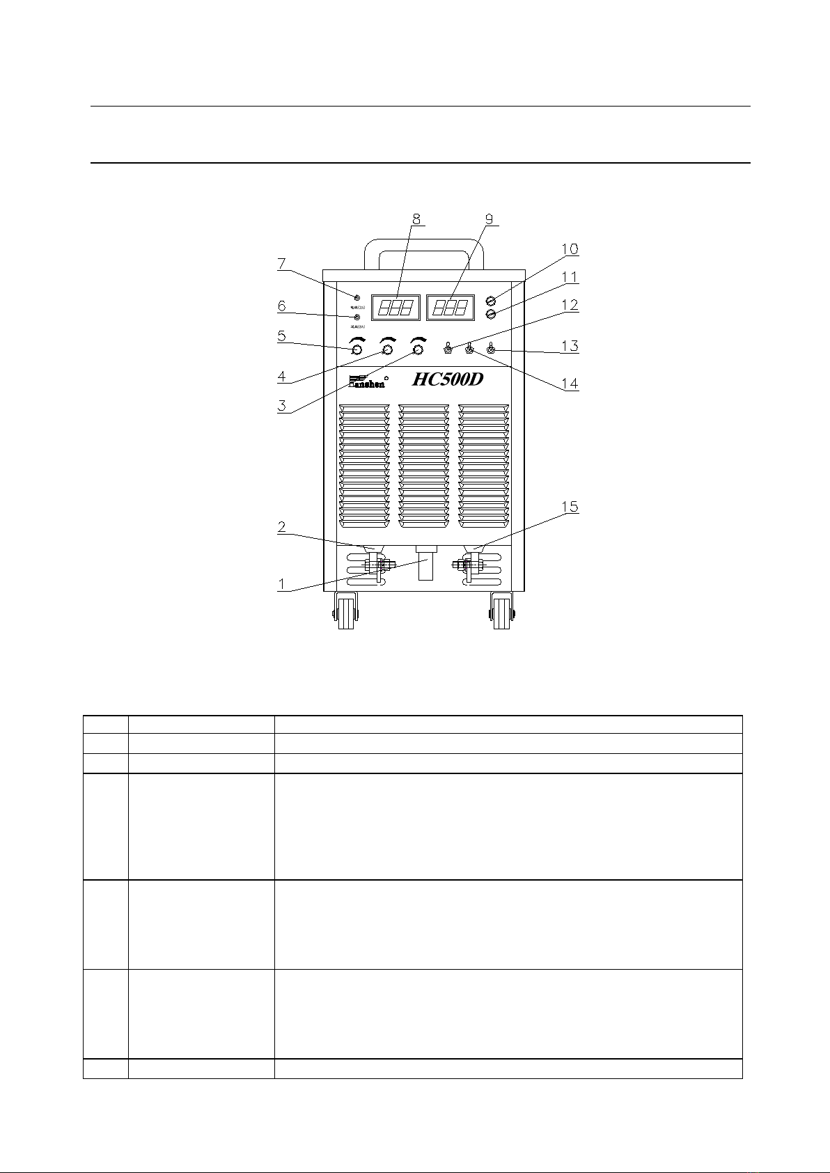
5.1 Front Panel
神
R
汉IGBT逆变式多功能焊机
-
+送丝机
手工焊
气保焊焊接
检气
收弧无
收弧有
弧特性收弧电流
(推力调节)(电流调节)(引弧电流)
软硬
收弧电压
异常
控制
电流显示电压显示
FIG 4
Table 3 Function on front panel
NO
NAME
FUNCTION
1
Wire feeder connect
For wire feeder control cable
2
+
For connection with wire feeder welding cable
3
CO2:arc character
MMA:arc force
current
GMAW Condition:Arc characteristic adjustment knob When do CO2
Arc Welding, it could change welding stability, penetration and spatter loss
coefficient.
MMA Condition:arc force current adjustment knob When do MMA, it is
used to change arc stiffness.
4
CO2:crater arc
current
MMA:adjust current
GMAW Condition:Crater current adjustment knob for adjusting the size
of crater current in ‘Crater On’ mode
MMA Condition:Welding current adjustment knob for adjusting the size
of output current
5
CO2:crater arc
voltage
MMA:arc start
current
GMAW Condition:Crater Voltage Adjustment Knob When do CO2 Arc
Welding, adjust the size of crater voltage in ‘Crater On’ mode
MMA Condition:Striking Current Adjustment Knob When do MMA, it
is used to change arc start current
6
Wire feeding (8A)
Wire-feeder fuse. The fuse is broken for protecting control transformer while

-10-
wire feeding circuit is short.
7
Power(2A)
Power fuse. The fuse is broken for protecting control transformer while
control electric circuit is short.
8
Voltage indicator
For output voltage adjust while welding
9
Current indicator
For welding current/output current adjust
10
Control
Indicate welding machine if is on or off
11
O.C
Abnormity indicator. If the indicator lights, the inner circuit is abnormal and
machine stops working.
12
Crater Arc
(ON/OFF)
Crater arc selection.
For CO2 welding while it is on “arc off” position, press the torch switch
for welding and loosen torch switch for welding stop, and this model is
suitable for short-time welding.
For GMAW welding while it is on “arc on” position, press the torch switch
and after arc ignition can loosen the torch switch, the normal welding can be
continued. Press the torch switch again, the arc will be reduced into a less
value which is set by adjusting the knob on front panel, and the weld will be
stop if you loosen the torch switch now. It is suitable for long-time welding.
13
MMA/CO2
Function switch,to chose working condition
14
Gas test/Weld
Gas test/weld selection. On “gas test” position can check the flux of CO2 or
argon; on “weld” position the machine works normally.
15
-
For connection with workpiece.
5.2 Back Panel
R
~
3
电源开
2
1ff
X
eff
1
2
I
2
1max
U
0
1
绝缘等级: F
电源关 ~
防护等级: IP21S
请勿他用。保险丝8A。
2
2
CO 调节器加热用电源(交流36V),
此为CO 调节器加热专用。仅作为
FIG 5
-11-
Table 5 Function on back panel
NO.
NAME
FUNCTION
1
Grounding Bolt
Connect this bolt for reliable grounding via wire or connect the input power supply
for reliable grounding.
2
Cooling Fan
For cooling inner calorific parts inside machine
3
Heating Fuse
(8A)
The fuse will be broken down for protecting transformer while the regulator is
short circuit.
4
Power supply for
heating
For supplying DC 36V to regulator(cannot be used for other places, otherwise,
bear your own consequences)
5
Power Switch
Be automatic power-off when welding machine is overload or malfunction.
Generally, the switch is to pull to the connection and to close or cut off input
power supply.
6
Nameplate
For description of parameters. Refer to it while operating
7
Power Cable Box
For connect with power supply in 380V
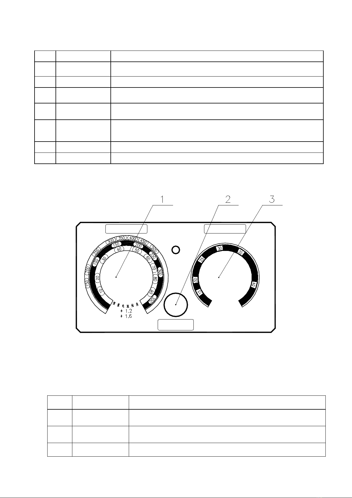
5.3 Wire Feeder Control Panel
AV
手 动 送 丝
I N C H I N G
WELDING VOLT.ADJ.
电 压 调 整
WELDING CUR.ADJ.
电 流 调 整
FIG 6 Control Panel for Wire Feeder
Table 6 Function for Control Panel of Wire Feeder
NO
NAME
FUNCTION
1
Current Adjust
For welding current adjust. The relative value of current is shown
from 10 to 100 by scale while presetting current.
2
Feeding Wire by
Manual
For feeding the wire into torch before welding.
3
Voltage Adjust
For welding voltage adjustment.

-12-
6、OPERATION
6.1 GMAW operation
6.1.1 Preparation
(1)Connect machine according to FIG 1.
(2)Open up the middle panel, shift“MMA/TIG/CO2”swith onto “CO2”model.
(3)Switch on the power supply MCB, the machine’s “power”indicator turns
light, cooling fan begins running and regulator turns heating.
(4)Select suitable wire for work piece, and select suitable wire-feeding roller
and contact lip of torch according to wire diameter.
(5)Press “feed sire by manual”knob and adjust “welding current” knob for
feeding the wire into torch.
(6)Shift “gas test/weld”switch onto“gas test”position, adjust regulator valve
for suitable flow value. After gas test shift the switch onto “weld” position.
6.1.2 Welding Operation
6.1.2.1 Spot welding or short welding
(1) Shift “crater arc on/off”onto “off” position
(2) Adjust “welding current” and “welding voltage” onto suitable value
according to welding technology (FIG 7 refer to GMAW technology
criterion).
(3) Press torch switch for welding, loosen torch switch for stop welding.
6.1.2.2 Long welding or welding in large current
(1)Shift “crater arc on/off” onto “on” position.
(2)Adjust “welding current”, “welding voltage”, “crater current” and “crater
voltage” according to welding technology.
(3)Press torch switch for arc ignition, then the machine goes onto normal
welding position. Here the welder can loosen torch switch for continuous
welding. If wants to stop welding, press torch switch again, now the
machine turns onto “crater arc” position, and the output current is
decreasing. After loosening the torch switch the welding stops.
(4)During welding process, adjust “Arc Characteristics” knob could change
arc stability, penetration and spatter loss coefficient.
6.2 SMAW Operation
6.2.1 Preparation
(1) Connect machine according to FIG 2.
(2) Shift “MMA/TIG/CO2” switch onto “MMA” model.
(3) Switch on the power supply MCB, the machine’s “power” indicator turns
light, cooling fan begins running.
(4) Select suitable electrode according to work piece.

-13-
6.2.2 Welding Operation
(1) Adjust “welding current onto suitable value according to work piece
thickness and electrode diameter (refer to Table 8)”. Could adjust striking
arc current properly to ensure reliable striking arc.
(2) The machine uses inverter control by adjust “arc force” to control
stiffness of arc and change metal transfer process to ensure welding
process running stably.
(3) While welding on all position, adjust “arc force” value bigger to avoid
conglutination between electrode and work piece; while welding in large
current or flat welding, adjust “arc force” value smaller or onto zero
position to decrease splash.
6.3 GTAW operation
6.3.1 Preparation
(1) Connect machine according to FIG 3.
(2) Shift “MMA/TIG/CO2” switch onto “MMA” model.
(3) Switch on the power supply MCB, the machine’s “power” indicator turns
light, cooling fan begins running.
(4) Select suitable dock needle and filler wire according to work piece.
(5) Adjust welding torch flow switch and select suitable flow. Shift switch
onto “off” position when not use.
6.3.2 Welding Operation
(1)Adjust “welding current” onto suitable value according to work piece
thickness(refer to table 9)
(2)The operation is : contact tungsten with work piece, press torch switch,
scratch work piece and uplift torch, the arc is ignited. Uplift torch when arc
is broken, elongate arc, force to broke arc.

-14-
6.4 Technology
Table 7 GMAW technical requirement (for reference only)
Thickness
(m m)
Wire
Diamete
r
( mmΦ)
Bottom
Clearance
G
(mm)
Welding
Current
(A)
Welding
Voltage
(V)
Weldin
g Speed
(cm/mi
n)
Operate
Clearance
(mm)
Gas
Flow
(L/min
)
L
O
W
S
P
E
E
D
0.8
0.8,0.9
0
6070
1616.5
5060
10
10
1.0
0.8,0.9
0
7585
1717.5
5060
10
1015
1.2
0.8,0.9
0
8090
1718
5060
10
1015
1.6
0.8,0.9
0
95105
1819
4550
10
1015
2.0
1.0,1.2
00.5
110120
1919.5
4550
10
1015
2.3
1.0,1.2
0.51.0
120130
19.520
4550
10
1015
3.2
1.0,1.2
1.01.2
140150
2021
4550
1015
1015
4.5
1.0,1.2
1.01.5
170185
2223
4050
15
15
6.0
surface
1.2
1.21.5
230260
2426
4050
15
1520
inner
1.2
1.21.5
230260
2426
4050
15
1520
9.0
surface
1.2
1.21.5
320340
3234
4050
15
1520
inner
1.2
1.21.5
320340
3234
4050
152
1520
F
A
S
T
S
P
E
E
D
0.8
0.8,0.9
0
89
16.5
120
10
15
1.0
0.8,0.9
0
100
17
120
10
15
1.2
0.8,0.9
0
110
18
120
10
15
1.6
1.0,1.2
0
160
19
120
10
15
2.0
1.0,1.2
0
180
20
80
15
15
2.3
1.0,1.2
0
200
22
100
15
20
3.2
1.2
0
240
25
100
15
20
Thick
ness
(mm)
Welding
Length
(mm)
Wire
Diameter
(mm)
Welding
Current
(A)
Weldin
g
Voltage
(V)
Weldin
g Speed
(cm/min)
Weldi
ng
Distanc
e (mm)
Posit
ion A
or B
Gas
Flow(L/
min)
L
O
W
S
P
E
E
D
1.0
2.53
0.8,0.9
7080
1718
5060
10
A
1015
1.2
33.5
0.9,1.0
8590
1819
5060
10
A
1015
1.6
33.5
1.0,1.2
100110
1819.5
5060
10
A
1015
2.0
33.5
1.0,1.2
115125
19.520
5060
10
A
1015
2.3
33.5
1.0,1.2
130140
19.521
5060
10
A
1015
3.2
3.54
1.0,1.2
150170
2122
4550
15
A
1520
4.5
4.55
1.0,1.2
180200
2324
4045
15
A
1520
6
55.5
1.2
230260
2527
4045
20
A
1520
8,9
67
1.2,1.6
270380
2935
4045
25
B
2025
F
A
S
T
S
P
E
E
D
12
78
1.2,1.6
300380
3235
3540
25
B
2025
1.0
22.5
0.8,0.9
140
1920
150
10
A
15
1.2
3
0.8,0.9
140
1920
110
10
A
15
1.6
3
1.0,1.2
180
2223
110
10
A
1520
2.0
3.5
1.2
210
24
110
15
A
20
2.3
3.5
1.2
230
25
100
20
A
25
3.2
3.5
1.2
260
27
100
20
A
25
4.5
4.5
1.2
280
30
80
20
B
25
6
5.5
1.2
300
33
70
25
B
25

-15-
thickness
(mm)
Welding
Diameter
(mm)
Welding
Current
(A)
Welding
Voltage
(V)
Welding
Speed
(cm/min)
Welding
Distance
(mm)
Position
A,B or
C
Gas Flow
(L/min)
L
O
W
S
P
E
E
D
0.8
0.8,0.9
6070
1617
4045
10
A
1015
1.2
0.8,0.9
8090
1819
4550
10
B
1015
1.6
0.8,0.9
90100
1920
4550
10
B
1015
2.3
0.8,0.9
100130
2021
4550
10
C
1015
1.0,1.2
120150
2021
4550
10
C
1015
3.2
1.0,1.2
150180
2022
3545
1015
C
1015
4.5
1.2
200250
2426
4050
1015
C
1015
F
A
S
T
S
P
E
E
D
2.3
3.2
1.2
220
24
150
15
B or C
25
300
26
250
15
B or C
25
Thickness
(mm)
Welding
Diameter
(mm)
Welding
Current
(A)
Welding
Voltage
(V)
Welding
Speed
(cm/min)
Welding
Distance
(mm)
Gas
Flow
(L/min)
L
O
W
S
P
E
E
D
1.6
0.8,0.9
6575
1617
4045
10
1015
2.3
0.8,0.9
80100
1920
4045
10
1015
3.2
1.0,1.2
130150
2022
3540
1015
1015
4.5
1.0,1.2
150180
2123
3035
1015
1015
Table 8 relation of electrode & welding current for SMAW (for reference only)
For alkaline electrode 507(GB E5015,AWS E7015 ,JIS D5015)
Rod Diameter(mm)
2.5
3.2
4.0
5.0
5.8
Welding Current(A)
60~90
90~120
140~180
170~210
210~260
For acidic electrode 422(GB E4303,AWS E6013 ,JIS D4303)
Rod Diameter(mm)
2.0
2.5
3.2
4.0
5.0
5.8
Welding Current(A)
40~70
70~90
90~130
160~210
220~270
260~310

-16-
Table 9 for GTAW (for reference only)
Work piece
thickness
(mm)
Tungsten
Diameter
(mm)
Wire Diameter
(mm)
Welding
Current
(A)
Clearance
(mm)
Groove
Condition
0.6
1.0~1.6
1.0
20~40
1
(1) (2)
1.0
1.0~1.6
1.6
30~50
1
(1) (2)
1.5
1.0~1.6
1.6
50~80
1
(2)
2.5
1.6~2.4
1.6~2.4
70~100
1
(2)
3.0
1.6~2.4
1.6~2.4
100~130
1~2
(2) (3)
4.0
2.4
1.6~2.4
120~160
2~3
(3) (4)
5.0
2.4~3.2
2.4~3.2
130~200
2~3
(3) (4)
6.0
2.4~3.2
2.4~3.2
150~240
3~4
(4)
8.0
3.2~4.0
3.2~4.0
180~31 5
4~5
(4)
(3)
(1)
(4)
(2)

-17-
7、DAILY MAINTENANCE AND TROUBLE SHOOTING
Warning:
Only after switching off the power supply and ensuring safety, the welding
machine can be opened up for check. Otherwise it may cause electric shock or
burn and other safety accidents
7.1 Attention :
a. Connect cable to port well. Any damage can influence the stability when
welding.
b. Forbid the bare cable and port to be touched by other metal, avoid short
circuit.
c. Avoid breaking the cable.
d. Avoid knocking or heavy weight.
e. Keep good ventilation.
f. Daily maintenance is not enough. In order to keep excellent performance,
periodic maintenance and checking and cleaning the inside components
is necessary.
g. In normal condition, there will be quantity of spark mote and oil dust.
Check and clean in every three months.
h. Check cables including the adjusting button and spares in panel regularly.
i. Change contact tube and wire feeder wheel and clear wire feeder pipe
regularly.
7.2 Trouble Shooting
NO
TROUBLE
POSSIBLE CAUSE
REPAIR
01
Switch on but indicator light
does not work
(1)Air switch could be out of
order.
(2)Power fuse is blown.
(1)change the controller
(2)change fuse
02
air switch on back panel
breaks.
(1)Air switch cannot work.
(2)IGBT mould is damaged
(3)3 phase commutate bridge is
damaged
(4)control PCB damaged
(1)change controller
(2)change IGBT mould
(3)change 3 phase
commutate bridge
(4)change panel
03
Too hot when welding
(1)over-load operating for long
time
(1)operate within load
04
Cannot adjust current
(1)controller cable of wire feeder
is damaged or control PCB is
damaged.
(2)the connection wire of current
divider may be damaged
(3)control PCB is damaged
(1)change
(2)fasten
(3)change
05
Unstable arc, big spatter
(1)wrong procedure
(2)contact tip wear
(1)correct procedure
(2)change contact tube
07
CO2 regulator does not work
(1)CO2 regulator is damaged
(1)change

-18-
(2)heating cable is broken
(3)fuse melts
(2)repair
(3)change 8A fuse
07
switch on the torch and can
feed wire but without gas
flow
(1)control PCB is damaged
(2)electromagnetism valve is
damaged
(1)change
(2)change
08
Wire feeder does not work
(1)gun switch is damaged
(2)feeder cable is broken
(1)change
(2)repair
7.3 Fixing
Normal Fixing:
a) Fuse melts, change fuse. If failure persists after change, switch off power
and consult manufacturer.
b) PCB Problem: Contact with manufacturer or dealer.
c) Other spare parts failure, check and change
d) Other: check whether there is wrong connection or loose connection.
7.4 After-sale Service
a) Check according to normal checking list.
b) Contact manufacturer if require technical support.
c) Please furnish the following information:
- Your name、address、contact number。
- Machine model and type
- Details of trouble or problem.

-19-
8、CIRCUIT DIAGRAM
送丝机电路
M
-
+
SSJ
QF
CZ2
CN9
97 97
105
87
86
45
6 12 3
38
38
47
115
115
61
115
67 1
2
3
4
5
6
7
8
76
75
15
74
73 1
2
3
4
5
CN8
1
2
3
4
5
6
7
8
52
52
50
50
51
51
34
35
49
115
48
98
97
96
3
2
1
3
2
1
1
1
2
3
4
71
70
15
33
CN7
~27.4V
~36V
CN5
1
2
115
40
CN1
CN10
CN3
W
V
U
~
~
~
BR1
RY4
Q1
5C1-6
C12
D1-3
D4-6
3-7R1,2 3-7C1
R1
4C1
4C2
C8,9
RY1
RY3
RY2
S1
C3
C2
C1
8TVS1
8 4
8 5
Q3 5C10-15
8TVS2
8 6
8 7
Q2
8TVS1
8 0
8 1
Q4
8TVS2
8 2
8 3
L4
10T/0.042mH
+
-
FL
500A/75m V
8 7
8 6
~ ~
RP3
47K
FUSE2
2A
C13
CBB61-1UF/500VAC
FUSE1
8A 9D29D1
A
15A502
V9R1
TS
IPB
RJ
~ ~
RP2
收弧电流
56
208
RP1
收弧电压
115
200
201
1
2
3
4
5
CN6
16
14
60
191
190
1
2
4
3
5
6
CN4
L1
L2
S3
S2
T2:FH4.702.002E
CN2
S3:收弧有/收弧无(图中为收弧有状态)
S2:焊接/检气(图中为检气状态)
电源
过热
CT2
M1-电压表 M2-电流表
弧特性
~10V
~19V
~19V
6
7
8
9
1
3
CT1
热继电器
FUSE3
8A
~27.4V
~27.4V
415V
380V
220V
0V
0V
T1:FH4.702.056
FS
20T
3T
3T
12T
DC24V
200FZY6-S/220V
JUC-17F-80℃±5
4K7
4K7
5R1,2,3,4,5
C4,5,6,7
L2
L3
5T
L1
B
A
8R3
8R4 8R4
8R3
97
96
1
3
2
3
4
5
97
2
1
CN5
CN6
CN7
CN4
85
84
8 5
8 4
1
3
CN3
83
82
8 3
8 2
1
3
CN2
81
80
8 1
8 0
1
3
CN1
~19V
~19V
1
98 2
2
2
2
2
3D1
3D2
3D3
3D4
3R1
A
B
HGQ
3-7R3,4 3-7C2
TR1
C10 C11
CT3
6T
993
1052
101
102
97
106
100
104
103
380V
415V
主控板AP1
HC-Ⅱ -AP1
FH7.820.292E
驱动板
HC-Ⅱ -AP 2
FH7.820.293C
电容板1
HC-Ⅱ -AP 5
FH7.820.296C
IGBT驱动吸收板
HC-Ⅱ -AP 8
FH7.820.327B
IGBT驱动吸收板
HC-Ⅱ -AP 8
FH7.820.327B
输出整流吸收板
HC-Ⅱ -AP 7
FH7.820.326A
输出整流吸收板
HC-Ⅱ -AP 7
FH7.820.326A
HC-Ⅱ -AP 4
FH7.820.295B
输出保护吸收板
指示灯板
HM-Ⅱ - AP 4
FH7.820.351
电流采样板
HC-Ⅱ -AP 3
FH7.820.294C
1
2
378
79
S4 S4:手工焊/气保焊(图中为手工焊状态)
This manual suits for next models
2
Table of contents
Other Hanshen Welding System manuals


Popular Welding System manuals by other brands


ADA INSTRUMENTS
ADA INSTRUMENTS IronWeld 160 operating manual

Kemppi
Kemppi KempArc Pulse 350 operating manual

HERKULES
HERKULES HES 150 T Original operating instructions

WELDING INDUSTRIES
WELDING INDUSTRIES Weldmatic 200i Operator's manual

Miller
Miller Intellifire 204 owner's manual

EWM
EWM TR-0102 operating instructions


