Hanshen MP350 Series User manual

1
OPERATION
MANUAL
DSP MULTIFUNCTION PULSE
WELDING MACHINE
MP350/500 series
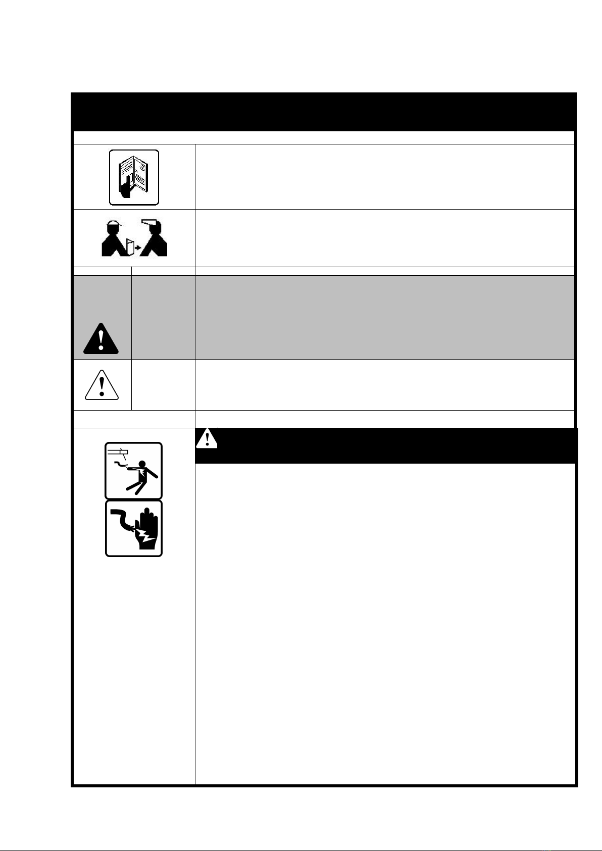
A T T E N T I O N :
Be sure that all installation, operation, maintenance and repair
procedure are performed only by qualified individuals.
Read this operation manual completely before using this equipment.
Save this manual and keep it handy for quick reference pay more
attention to the safety instructions.

2
CATALOGUE
1、S A F E T Y R U L E S … … … … … … … … … … … … … … … … … … 3
2、S P E C I F I C A T I O N … … … … … … … … … … … … … … … … … 8
3、T E C H N I C A L P A R A M E T E R S … … … … … … … … … … … … 9
4、E Q U I P M E N T I N S T A L L A T I O N & C O N N E C T I O N … … … … 1 0
5、F U N C T I O N I N T R O D U C T I O N … … … … … … … … … … … … 1 2
6、W E L D I N G O P E R A T I O N … … … … … … … … … … … … … … 2 2
7、W E L D I N G M A T E R I A L S E L E C T I O N … … … … … … … … 3 5
8、D A I L Y M A I N T E N A N C E … … … … … … … … … … … … … … 3 6
9、C I R C U I T D I A G R A M … … … … … … … … … … … … … … … … 4 2
10、WIRING DIAGRAM FOR INTEGRATED WELDING MACHINE.......................44
3
1、SAFETY RULES
S a f e t y R u l e s
Please read the manual carefully before using the machine and
operating it correctly on this basis
This manual only for the installation, operation and maintenance
This operator should have received appropriate training
Please keep this manual or a copy to the welding machine operator
Installation, repair and maintenance personnel should also read the
operating instructions
Warning
Installation and maintenance of professional electrician to carry out
operations
Operation of electrical connections must disconnect the power
switch of the distribution box
Do not allow minors to close to the welding machine and welding
site
Note
The machine should be placed horizontal, the tilt angle should not
exceed 15°
Do not use this machine to thaw pipes.
A n e l e c t r i c s h o c k c a n b e fa t a l .
Be sure to turn off the power switch of the power distribution box
when wiring
Do not touch the exposed live parts
Do not touch the overheating parts produced by the current between
the welding and the workpiece with bare hands, or place parts of
body(or wet clothes)in the welding circuit to form a loop, when the
machine is working
Touching the electrodes of two power source at the same time may
cause electric shock damage
Do not loop any cables or other leads around your body or any parts of
your body
All cables and other leads must be firmly attached, undamaged,
properly insulated and adequately dimensioned. Immediately replace
any loose connections, scorched, damaged or under dimensioned
cables or other leads
In MIG/MAG welding, the welding wire, welding spool, the drive
rollers and all metal parts having a connection with the welding wire
are also live
The machine should be reliably grounded, and have the mains and the
machine supply leads checked regularly by a qualified electrician to
ensure that PE(protective earth)conductor is functioning correctly
Do not discharge the TIG torch when aiming at any part of the body

4
O v e r h e a t e d p a r t s m a y i n j u r e t h e sk i n
Do not touch the overheated welding position
Do not touch with bare hands the welding cable or welding clamp due
to the heat produced during operation. Welding slag in the weld
cooling may collapse from the surface. The operator and nearby
persons should wear goggles well and other protective equipment when
dealing with welded materials
W e l d i n g p r o c e s s m a y c a u s e f i r e o r
e x p l o s i o n
Spatter may ignite nearby combustibles. Combustible materials must
be at least 10 meters away from arc, or else must be covered over with
approved coverings
Have a suitable, approved fire extinguisher in the welding suit
Control the spatter from falling on clothes or the body
Do not perform welding in location that are at risk from fire or
explosion, or in enclosed tanks, barrels or pipes, unless the latter have
been prepared for welding in accordance with the relevant national and
international standards. Sparks and hot metal particles may also get
into surrounding areas through small crack and holes. Take suitable
measures here to ensure that there is no risk of injury
Welding must never be performed on containers which still have gases,
fuels, mineral oils etc. Traces of these substance left in the containers
are a major explosion hazard.
The fumes given off during welding contain gases and vapors are
harmful to health
Welding fumes may contain substances which may cause birth defects
and cancer
Do not inhale any fumes or noxious gases that are given off
Air circulation to maintain the welding site, welding site should be
proper ventilation exhaust soot facilities
The situation with insufficient ventilation should use a respirator mask
with an independent air supply
The harmful of welding fumes will depend on the following
components: the metals used in and for the workpiece, electrodes,
coating, cleaning and degreasing agents and the like
Lift up with forklift or hoist. When hoisting the machine by crane, only
use suitable manufacturer supplied lifting devices
Remove the cylinder and the wire feeder unit(MIG/MAG welder
units)before hoisting
When using a crane to lift, tie the rope around two handles at the same
time
5
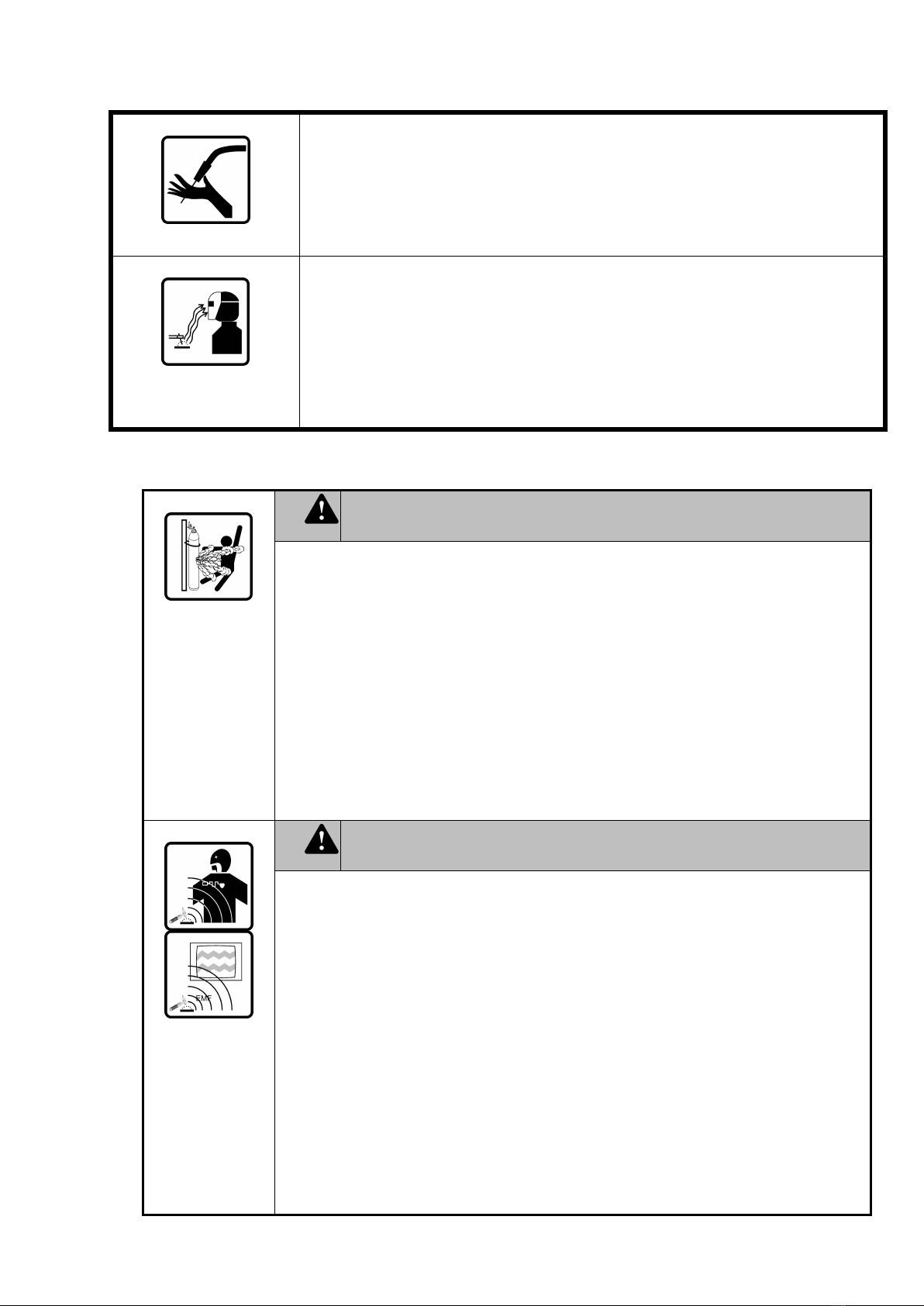
When the welding wire emerges from the torch, there is a high risk of
injury (the wire may pierce the welder’s hand. injure his face and eyes)
For this reason, when feeder-inching etc., always hold away from your
body (machines with wire feeder)
Strong arc burns the eyes and skin
The UV rays generated by arc will damage skin and eyes, please wear
welding labor clothing when welding
Protect the eyes and face from UV, heat and flying sparks with an
appropriate safety shield containing appropriate regulation filter glass
Wear a pair of appropriate regulation goggles (with side guards) behind
the safety shield
C y l i n d e r s ma y h a v e a p o t e n t i a l r i s k o f
a n e x p l o s i o n
Protect shielding-gas cylinder from excessive heat, mechanical impact,
slag, naked flames, sparks and arcs
Place cylinders preferably away from the welding site and fasten them
firmly
Never hang a welding torch on a shielding-gas cylinder
Never perform welding on a pressurized shielding-gas cylinder
Use only shielding-gas cylinders that are suitable for the application in
question, together with matching, suitable accessories (pressure
regulator, hoses, fitting and hose clamp)
When opening the valve of a shielding-gas cylinder, always keep your
face away from the outlet nozzle
When the shielding-gas cylinder is not connected up, leave the cap in
place on the shielding-gas cylinder valve
E l e c t r o m a g n e t i c f i e l d ma y h a v e a c e r t a i n
d e g r e e o f h a z a r d
When current flows through a conductor or TIG welding, high
frequency arc is generated, which will induce an electromagnetic field
(EMF). When welding, the welding cable around will form the
electromagnetic fields
Electromagnetic fields may interfere with pacemakers and other medical
equipment, if the welders wear such equipment, please consult a doctor
before the welding operation
Electromagnetic field may cause as yet unknown damage to health, in
order to minimise electromagnetic damage, please try to do the
following points:
Keep the cables as short as possible
Arrange the cables so that they run close together (to prevent EMI
problems as well)
Do not arrange cables around the body
Try to ensure the cables connecting machines and workpiece are on the
same side of your body
6
●The electromagnetic fields may have some interference with radio
waves, computer, communications equipment and some other telecoms
equipment, the owner/operator is obliged to take all necessary measures
to prevent such interference.
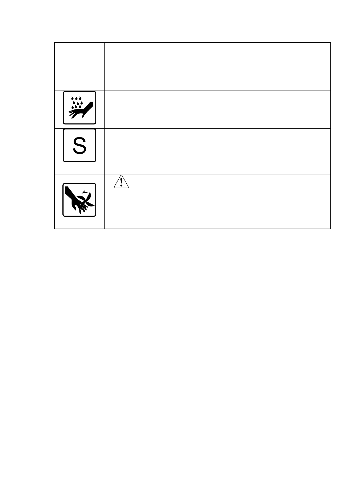
To prevent the risk of scalding from accidental discharge of hot coolant,
before unplugging the connectors of coolant flow, switch off the
cooling unit first.
If need to use the machine under electricity environment, only use it
when the safety symbol □s is found in such environment.
R o t a t i o n o f t h e f a n ma y i n j u r e yo u r b o d y
Do not insert hands or fine material into the fan cover
Please ensure that the case has been covered before opening a welding
power
Do not let children go near the machine repair or maintenance places

7
The machine may only be used for jobs as defined by the “Intended
purpose”:
-The machine may only be used for the welding processes stated on
rating plate. Utilisation for any other purpose, or in any other
manner, shall be deemed to not be in accordance with the intended
purpose, the manufacturer shall not be liable for any damage
resulting from such improper use.
Accordance with ‘intended purpose’ also comprises:
-Completely read and follow all the instructions given in this manual
-Completely read and follow all the safety instructions and danger
warnings
-Performing all stipulated inspection and servicing work
The application must never be used for the following:
-Thawing pipes
-Charging batteries/accumulators
-Starting engines
The machine is designed to be used in industrial and workshop
environments. The manufacturer shall not be liable for any damage
resulting from using of the machine in residential premises
Likewise the manufacturer will accept no liability for defective or
faulty work results
Operation or storage of the power source outside the stipulated range is
deemed to not be in accordance with the intended use. The manufacturer
shall not be liable for any damage resulting from such.
Temperature range of ambient air:
-The use of ambient temperature:-10°C~+40°C
-Preservation and transport temperature:-25°C~+55°C
Relative atmospheric humidity:
-+40°C up to 50%
--20°C up to 90%
Ambient air:Free of dust, acids, corrosive gases or substances etc
The delivery of the printed text and images in this manual have been
checked. The company reserves the right to modify the instructions in
the case without notice. This manual does not mean that the user has
made any commitments and guarantees. We appreciate any advice
given.

8
2、SPECIFICATIONS
Hanshen MP series DSP welding machines are fully digitally controlled inverter power
source. Its core is the digital signal processor (DSP). The DSP centrally deals with the
welding data, controls and monitors the welding process, which gives a reliable, premium
performance and welding quality. Besides, there is an intellectualised parameters combination,
which uses the synergic mode, and is also capable of saving 100 welding expert database
process. It has largely simplified the operation, which could transform a beginner welder into
an expert.
MP series inverter pulse MIG/MAG welding machine combines all 5 welding methods
in 1:
1.The pulse (both double and single); 2. Constant voltage; 3. Arc hand; 4. Argon welding
and 5. Carbon arc air gouging welding.
Currently, the pulse welding method could be used to weld many materials such as
carbon steel and stainless steel, aluminum and its alloys, copper and its alloys and other non-
ferrous metal welding. The constant pressure welding method can be used for carbon steel
rich in argon and CO2gas shielded welding.
Advantages:
1) Fully digitally controlled system, accurate control of welding process, stable arc
length
2) Full Digital wire feeding control system, wire feeding is accurate and smooth
3) Built-in welding expert database system, automatic intelligent parameter combination
4) Friendly operation interface, multi adjustment methods, easy to master.
5) Less welding spatter and nice weld appearance.
6) It can store 100 sets of welding procedure, which saves operating time.
7) Special four steps function for welding thermal conductive metal, arc starting and arc
welding quality is premium.
8) With various interfaces, which can be used to dock the tailor made welding machine
(when using as a power source) and the welding robot (optional).
9) Soft switch inverter technology, which can enhance the reliability and energy saving.
10) Double pulse function can give beautiful scales striate weld appearance.
11) Can match the digital welding torch, adjustment faster and more convenient
(optional).

9
3、TECHNICAL SPECIFICATIONS
Table 1:Specifications
Specification
MP350
MP500
1
Power source
voltage/frequency
AC 3 phase 380V10% 50Hz
2
Rated power input
16.5KVA
24KVA
3
Rated input current
25A
36A
4
Rated duty cycle
60%
5
Range of rated output
current adjusting
20--350A
20-500A
6
Range of rated output
voltage adjusting
11--34V
11-40V
7
Output open circuit
voltage
58V
68V
8
Efficiency
≥85%
9
Efficiency factor
≥0.93
10
Wire diameter (mm)
Ф0.8、Ф1.0、Ф1.2、Ф1.6
11
Net weight (kg)
47
52
12
Dimension (mm)
690×335×720
690×335×720
13
Insulation class
F
14
Shield protection class
IP21S
10
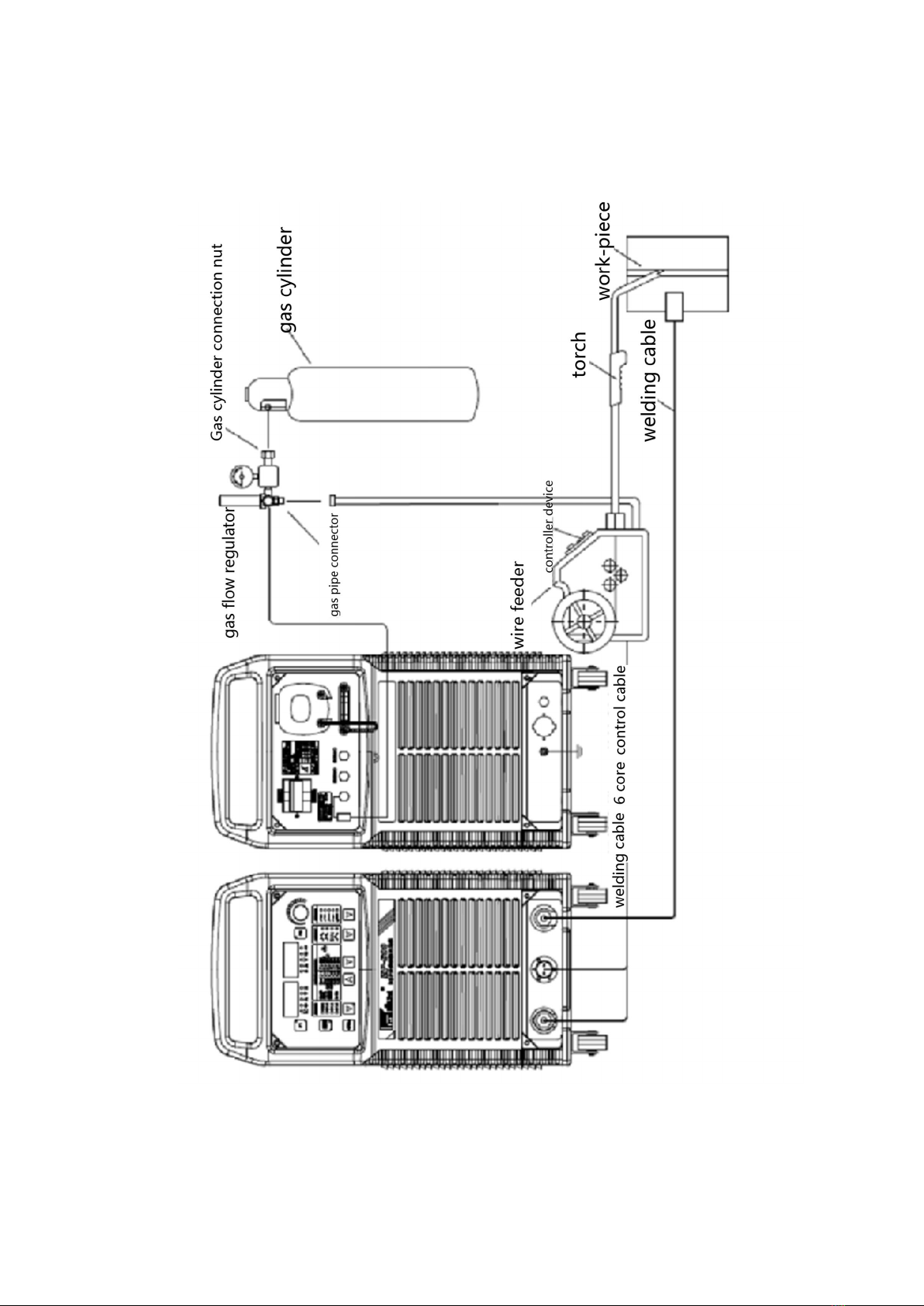
4、EQUIPMENT INSTALLATION & CONNECTION
4.1 Connection diagram (for example: melting pole welding)
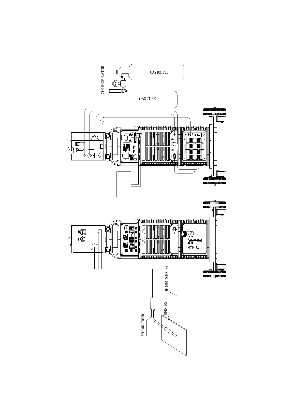
11
3-415V
Fig.1:connection diagram

12
4.2 Safety tips
Note:
Please strictly stick to the following steps for installation and debugging
The operation of connecting the gas cylinders can only start after turning
off the power switch of distribution box.
Warning
Electric shock
may injure
body or may be
fatal
Welding process may cause fire
or explosion
Spatter may ignite nearby
combustibles. Combustible
materials must be at least 10m
away from the arc, or else must
be covered over with approved
coverings
Avoid spatter falling on the
clothes or the body
Be sure turn off the power
switch of the power
distribution box when wiring
Do not touch the exposed
live parts
The fumes given off during
welding is harmful to health
Do not inhale any fumes or
noxious
Clean up the oil spill on the
workpiece
Keep air circulation of
welding site
Welding station should be
equipped with exhaust smoke
and dust cleaning equipment
Strong arc burns the eyes and
skin
The UV rays generated by arc
will damage skin and eyes, please
wear welding labor clothing when
welding
Overheated parts may
injure the skin
Do not touch the
overheated welding position
Do not touch the welding
cable or welding clamp with
bare hands due to the welding
heat
High speed mobile content may
cause injury
Do not insert hands or fine
content into the fan cover
Please ensure the case has
been covered before opening a
welding power
To prevent eyes and skin injury, please follow
labor safety and health rules, wear the necessary
protective equipment
Operation should be in accordance with the
relevant work safety operating rules

13
5、FUNCTION INTRODUCTION
5.1 MP front panel structure
Fig 2:MP-500 front panel diagram
Table 2:
No.
Item
Function
1
Operation panel
Adjust parameters, function selection, etc. read instructions for
operation manual of MP series welding machine panel
2
Cathode output
connector
Through the output cable to connect the welding workpieces (gas
metal arc welding)
3
Control cable interface
Connecting wire feeder control cable
4
Anode output
connector
Connecting wire feeder welding cable (gas metal arc welding)
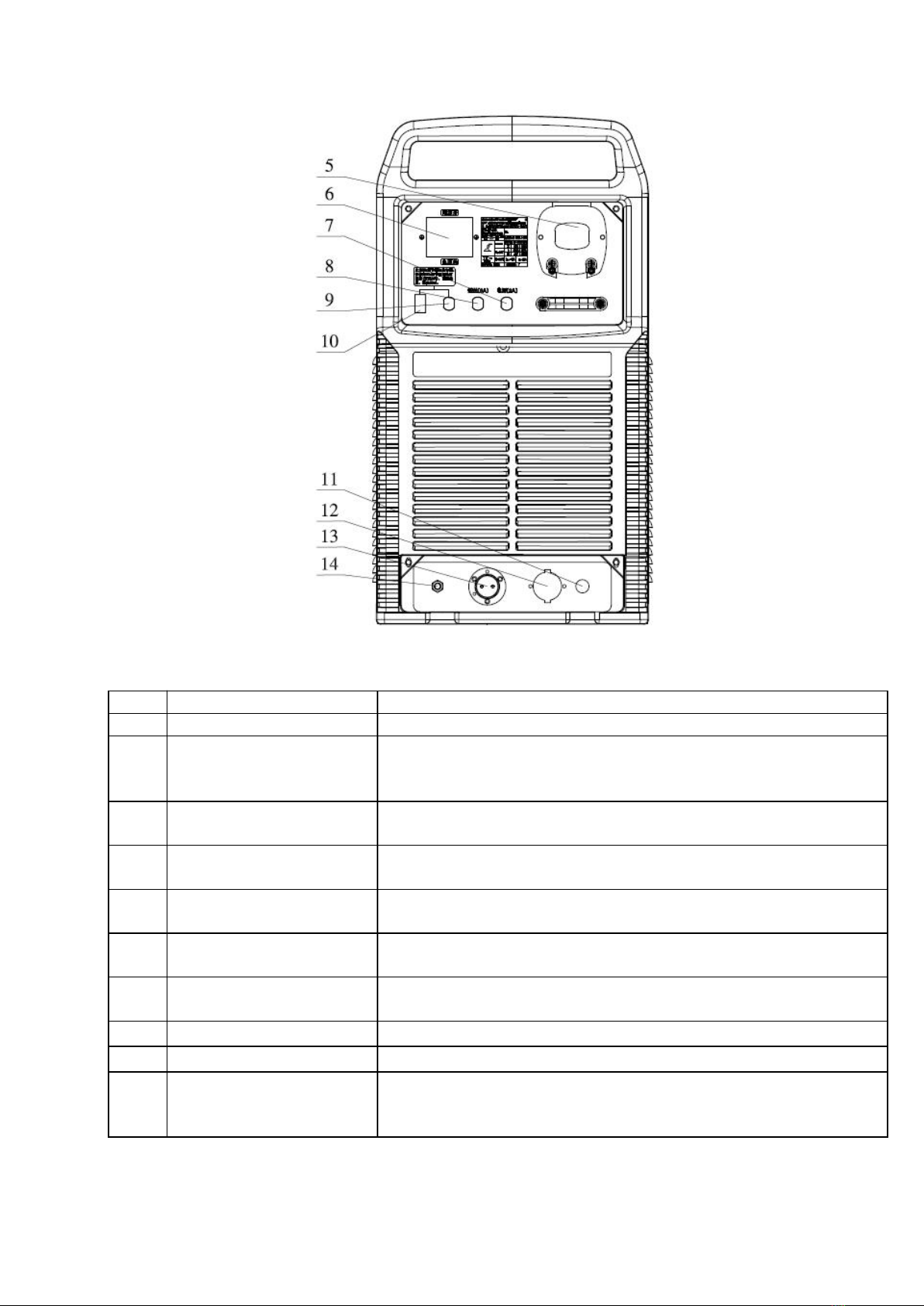
5.2 MP back panel structure
14
Fig3:MP-500 back panel diagram
Table 3
No.
Item
Function
5
Input power supply box
Used to connect the welding machine to 380V power supply
6
Air switch
This switch can automatically turn off power to protect the
welding machine during the overload or failure. In general, this
switch should be kept on
7
Control power fuse
When the control circuit short circuit occurs, this fuse will blow
to protect the voltage transformers, cooling fans and etc.
8
Wire feeder fuse
When the feeding circuit short circuit occurs, the fuse will blow
to protect the voltage transformer, cooling fan and etc.
9
Heating power fuse
When the heating regulator short circuit occurs, the fuse will blow
to protect control transformer ,cooling fan and etc
10
Heating output power
socket
Supply 36V heating regulator flowmeter
11
Water cooling switch
socket
Use for water cooling tank, water flow switch interface
(integrated machine)
12
Anode output connector
Connecting wire feeder cables (integrated machine)
13
Control cable connector
Connecting wire feeder control cables (integrated machine)
14
Grounding bolt
In order to ensure the personal safety, please be sure to use wires
to the bolt and reliable grounding, or reliable grounding line of
the input cable grounding.
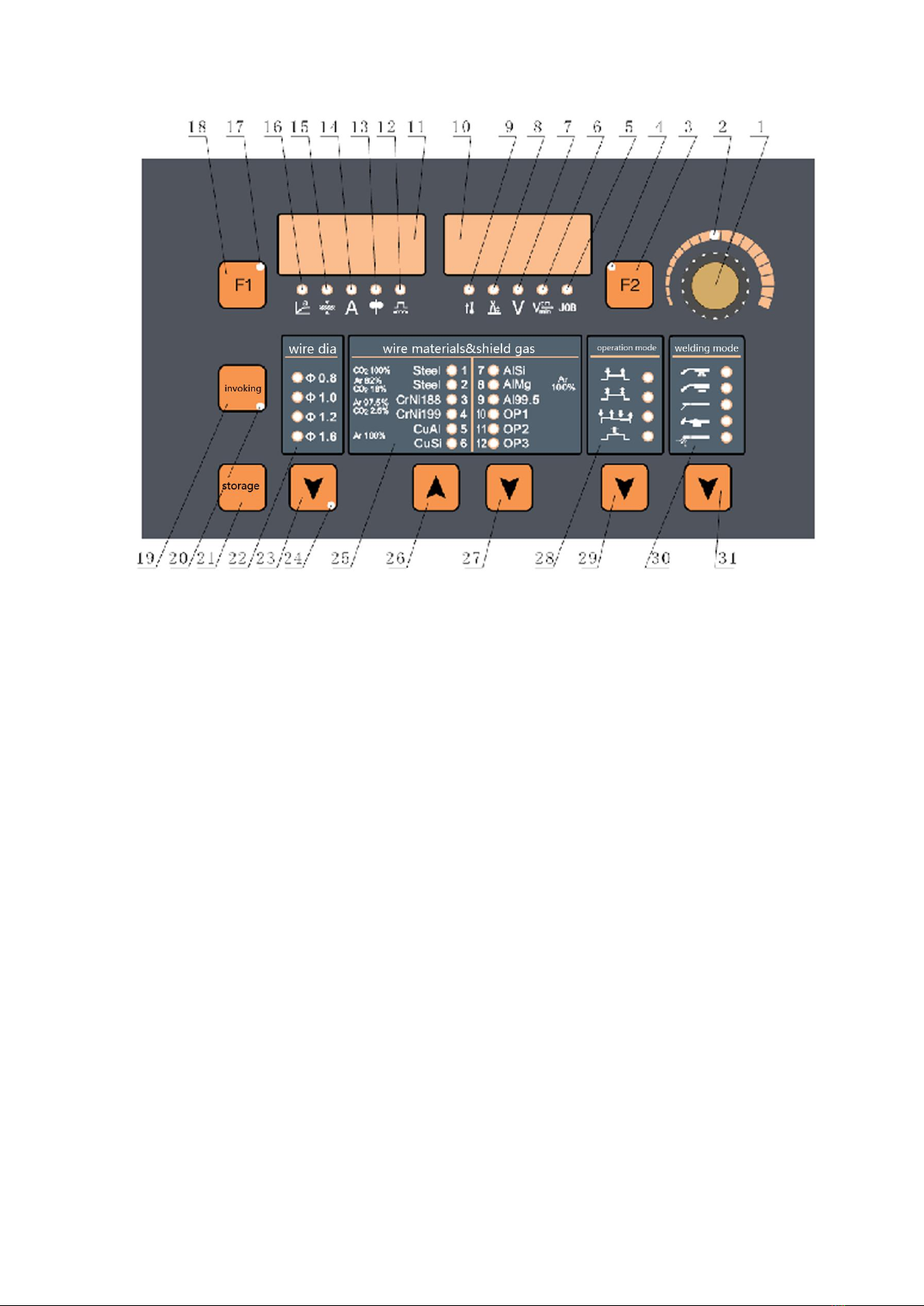
5.3、Mp series control panel instructions
15
Fig4:MP series welding machine operation panel schematic diagram
1)Adjusting knob
Adjust the parameter values. When Indicator light is on, it means the knob can be used to
adjust the corresponding parameter of the project.
2)Indicator light of adjusting knob
When indicator light is on, it means the knob can adjust the parameters
3)Selection key F2
Choose to operate the parameters of the project:
- Arc length correction
- welding voltage
- job no. n0
4)indicator light of key F2
When F2 indicator light is on, it means that F2 key has been selected and it can adjust the
parameters
5)indicator light of job no. n0
Obtain the preset parameters stored based on the job number

16
6)indicator light of welding speed
When indicator light is on, the display screen on the right shows the preset welding speed
(cm/min)
7)indicator of welding voltage
When indicator light is on, right display shows preset or actual welding voltage
8)indicator light of arc length correction
When indicator light is on, the display screen on the right shows arc length correction
value
— indicates Arc length shorter
0 indicates Standard arc length
+indicates Arc length longer
9)indicator light of inner temperature
The function is the reserve function; it is not operational at the moment
10)The display screen on the right
Display related parameters
11)The display screen on the left
Display related parameters
12)indicator light of the arc force/arc lamp
When using pulse MIG/MAG welding, it is used to adjust the arc force
— indicates arc force decrease
0 indicates standard arc force
+indicates arc force increase
When MIG/MAG unifies DC welding, it changes the arc stiffness of the short circuit
transition.
— indicates hard and arc stability
0 indicates secondary arc
+Soft arc, little splash
13)indicator of feeding speed
When indicator light is on, left display shows the feeding speed (M/min)
14)indicator light of welding current
When indicator light is on, the display screen on the left shows preset or actual welding
current
15)indicator light of base metal thickness

17
When indicator light is on, the display screen on the left shows the preset base metal
thickness
16)indicator light of welding angle
When indicator light is on, the display screen on the leftshows welding angle size ‘a’
17)indicator light of F1
When indicator light is on, it means that F1 key has been selected and it can adjust the
parameters
18)selection key F1
Choose to operate the parameters of the project:
- feeding speed
- welding current
- arc force/arc stiffness
19)Invoking key
Obtain parameters stored in advance
20)indicator light of invoking key
When indicator light is on, it means it can obtain the preset parameters stored
21)storage key
Enter the settings menu or store parameters
22)indicator light of wire diameter
When indicator light is on, it means it can adjust wire diameter
23)selection key of wire diameter
Select suitable wire diameter
24)indicator light of implicit parameter menu
When indicator light is on, it means that can adjust implicit parameter
25)indicator light of wire materials and protective gas
When indicator light is on, it means the corresponding wire materials and protective gas
are selected
26)Wire material selection button up
Welding wire materials and protective gas upward selection.
27)Wire material selection button down
Welding wire materials and protective gas downward selection
28)indicator light of welding torch operation mode
When indicator light is on, it means the corresponding operation mode is selected

18
29)welding torch operation mode button
Select the welding torch operation mode
Table 4:welding torch operation mode
Mode
Remark
Two steps
Normal operation mode
Four steps
Locked operation mode
Special four steps
Up, crater arc adjustable
model
Spot welding
Automatically control
working time
30)indicator light of welding method
When indicator light is on, it means the corresponding welding method is selected
31)selection button of welding method
Table 5:welding method
Welding methods
Note
P-MIG
Pulse welding
MIG/MAG
Unified dc welding
STICK
Manual welding
TIG
Tungsten argon arc
welding
CAC-A
Carbon arc air gouging
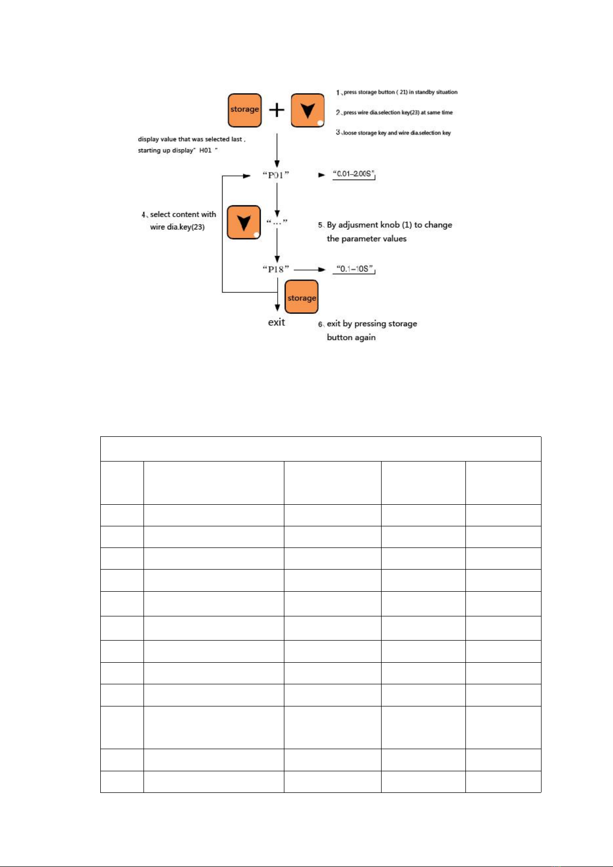
5.4 Implicit parameter adjustment
For implicit parameter adjustment method, see Fig5 and Fig6
At the same time press the store button (21) and the wire diameter selection key (23)
and then release, implicit parameter menu indicator (24) light is on, it means it has entered the
implicit parameter adjustment mode menu. Press the store button again (21) to exit the
implicit parameter menu adjustment mode; the implicit parameter menu indicator light is off.
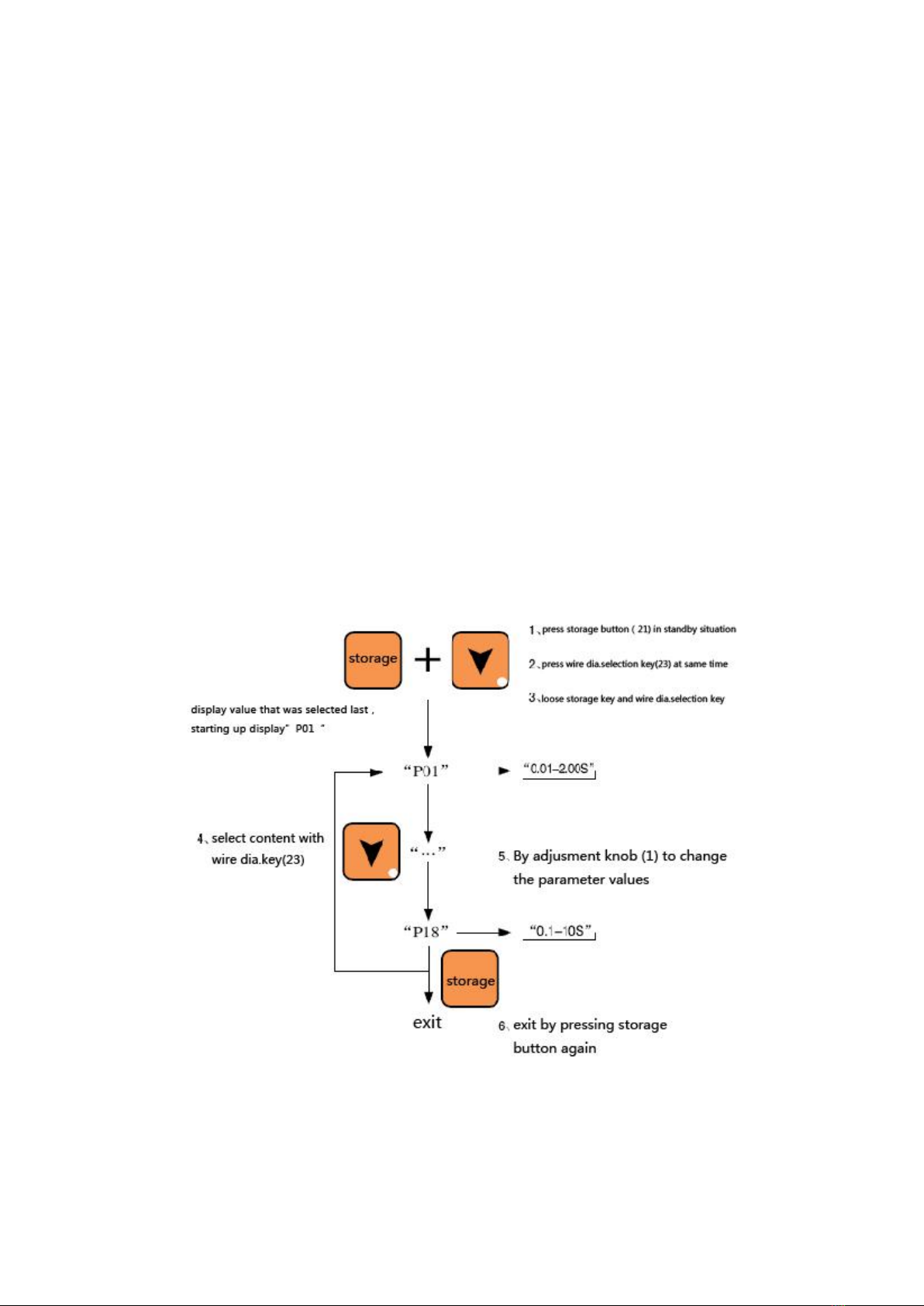
19
Use the wire diameter selection button (23) and choose to modify the content. Use the
adjusting knob (1) to adjust to parameter values. P05, P06 item are available for F2 key
switch to display current percentage, arc length offsets, and can also use (1) to modify the
parameter values.
Detailed operation reference (Fig 5 and 6):
Fig 5:Implicit parameter operation schematic diagram (melting polar gas shielded welding )
20
Fig 6:Implicit parameter operation schematic diagram (electrode MMA welding )
5.5 Modify the content and the corresponding parameters as shown in table 6
Gas shielded welding way implicit parameter is as follows:
Item
Function
Setting range
Individual-use
Unit
Factory
setting
P01
Back to the burning time
0.01-2.00s
0.01s
0.08s
P02
Slow wire feeding speed
1.0-21.0 M/min
0.1 M/min
3.6 M/min
P03
time of Plenum ahead
0.1-10.0s
0.1s
0.20s
P04
time of Stop lagging gas
0.1-10.0s
0.1s
1.0s
P05
early specification
1-200%
1%
135%
P06
Are-receive specification
1-200%
1%
50%
P07
transient time
0.1-10.0s
0.1s
1.0s
P08
Spot welding time
0.5-5.0s
0.1s
2.0s
P09
Close-control
OFF/ON
――
OFF
P10
Selection of water
cooling
OFF/ON
――
OFF
P11
Double pulse frequency
0.5-5.0Hz
0.1Hz
OFF
P12
Strong pulse group arc
-50-+50
1
0
This manual suits for next models
1
Table of contents
Other Hanshen Welding System manuals


Popular Welding System manuals by other brands

SAF
SAF NERTABLOC TH 400 PW Safety instruction for use and maintenance

Lincoln Electric
Lincoln Electric LINC 405-S Operator's manual

Lincoln Electric
Lincoln Electric US-CW139 datasheet

Magmaweld
Magmaweld ID 500 M/MW PULSE user manual

Migatronic
Migatronic CMI 183i user guide

LORCH
LORCH M-Pro BasicPlus Operation manual


