Panasonic PAN1740 Guide

PAN1740/1740A
Bluetooth®Low Energy Module
Design Guide
Rev. 1.0
Wireless Modules

PAN1740/1740A Bluetooth Module
Design Guide Rev. 1.0 Page 2
By purchase of any of the products described in this document the customer accepts the document's
validity and declares their agreement and understanding of its contents and recommendations. Panasonic
Industrial Devices Europe GmbH (Panasonic) reserves the right to make changes as required at any time
without notification. Please consult the most recently issued Design Guide before initiating or completing a
design.
© Panasonic Industrial Devices Europe GmbH 2019.
This specification sheet is copyrighted. Reproduction of this document is permissible only if reproduction is
without alteration and is accompanied by all associated warranties, conditions, limitations, and notices. Do
not disclose it to a third party.
All rights reserved.
This Design Guide does not lodge the claim to be complete and free of mistakes.
Engineering Samples (ES)
If Engineering Samples are delivered to the customer, these samples have the status “Engineering
Samples”. This means that the design of this product is not yet concluded. Engineering Samples may be
partially or fully functional, and they may differ from the published Product Specification.
Engineering Samples are not qualified and they are not to be used for reliability testing or series
production.
Disclaimer
The customer acknowledges that samples may deviate from the Design Guide and may bear defects due
to their status of development and the lack of qualification mentioned above.
Panasonic rejects any liability or product warranty for Engineering Samples. In particular, Panasonic
disclaims liability for damages caused by:
The use of the Engineering Sample other than for evaluation purposes, particularly the installation
or integration in another product to be sold by the customer,
Deviation or lapse in function of the Engineering Sample,
Improper use of the Engineering Sample.
Panasonic Industrial Devices EuropeGmbH disclaims any liability for consequential and incidental
damages. In case of any queries regarding the Engineering Samples, please contact your local sales
partner or the related product manager.

PAN1740/1740A Bluetooth Module
Design Guide Rev. 1.0 Page 3
Table of Contents
1About This Document .................................................................................................................. 4
1.1 Purpose and Audience......................................................................................................... 4
1.2 Revision History .................................................................................................................. 4
1.3 Use of Symbols................................................................................................................... 4
1.4 Related Documents............................................................................................................. 5
2Overview....................................................................................................................................... 6
2.1 PAN1740 ............................................................................................................................ 6
2.2 PAN1740A.......................................................................................................................... 6
3Reference Design......................................................................................................................... 8
3.1 USB-Dongle........................................................................................................................ 8
3.2 Mother Board ...................................................................................................................... 9
3.3 Adapter Board................................................................................................................... 10
3.4 Placement Recommendations............................................................................................ 11
4Run the Keil Project (Example).................................................................................................. 13
5Proximity Profile with two PAN1740/1740A USB-Dongles (Example) ....................................... 16
6Smart Snippets........................................................................................................................... 19
6.1 Program Structure............................................................................................................. 19
6.2 Application Demo: Proximity Profile.................................................................................... 23
7Dialog Serial Port Service (DSPS).............................................................................................. 25
7.1 Pro Kit with PAN1740/1740A Adapter Board (iPod)............................................................. 25
7.2 Two Pro Kits with PAN1740/1740A Adapter Board ............................................................. 28
7.3 Two PAN1740/1740A USB Sticks...................................................................................... 28
8Production Tools........................................................................................................................ 30
9Life Support Policy..................................................................................................................... 31
10 Appendix.................................................................................................................................... 32
10.1 Ordering Information.......................................................................................................... 32
10.2 Contact Details.................................................................................................................. 34
PAN1740/1740A Bluetooth Module
1 About This Document
Design Guide Rev. 1.0 Page 4
1 About This Document
1.1 Purpose and Audience
This Design Guide applies to the Bluetooth development modules PAN1740 and PAN1740A
Experimenter Kit (PAN1740 EXP and PAN1740A EXP). The intention is to enable our
customers to easily and quickly integrate Panasonic’s module PAN1740 and PAN1740A in their
product. The product is referred to as “the PAN1740/1740A” or “the module” within this
document.
This Design Guide describes the hardware and gives useful hints.
1.2 Revision History
Revision
Date
Modifications/Remarks
1.0
2019-11-07
First version
1.3 Use of Symbols
Symbol
Description
Note
Indicates important information for the proper use of the product.
Non-observance can lead to errors.
Attention
Indicates important notes that, if not observed, can put the product’s functionality
at risk.
Tip
Indicates useful information designed to facilitate working with the Module.
[chapter number]
[chapter title]
Cross reference
Indicates cross references within the document.
Example:
Description of the symbols used in this document 1.3 Use of Symbols.
Requirement
Indicates a requirement that must be met before the corresponding tasks can be
completed.
Result
Indicates the result of a task or the result of a series of tasks.

PAN1740/1740A Bluetooth Module
1 About This Document
Design Guide Rev. 1.0 Page 5
Symbol
Description
This font
GUI text
Indicates fixed terms and text of the graphical user interface.
Example:
Click Save.
This font
File names, messages, user input
Indicates file names or messages and information displayed on the screen or to
be selected or entered by the user.
Examples:
pan1760.c contains the actual module initialization.
The message Failed to save your data is displayed.
Enter the value Product 123.
1.4 Related Documents
Please refer to the Panasonic website for more information as well as related documents
10.2.2 Product Information.

PAN1740/1740A Bluetooth Module
2 Overview
Design Guide Rev. 1.0 Page 6
2 Overview
2.1 PAN1740
The PAN1740 is a short-range Bluetooth Low Energy (LE) single mode module used for the
implementation of Bluetooth functionality into various electronic devices. The PAN1740 is
fully compliant with the Bluetooth 4.1 standard. It includes dedicated hardware for Link Layer
Implementation of BluetoothLE and interface controllers for enhanced connectivity capabilities.
Block Diagram
2.2 PAN1740A
The PAN1740A is an optimized version of the PAN1740, offering a reduced boot time and
supporting up to eight connections. It has a fully integrated radio transceiver and baseband
processor for Bluetooth 5 LE. It can be used as a stand-alone application processor or as a data
pump in hosted systems. The device is optimized for remote control units (RCU) requiring
support for voice commands and motion/gesture recognition. Its integrated Audio Unit (AU)
offers easy interface for MEMS microphones over PDM, external codecs over PCM/I2S, and a
Sample Rate Converter unit. The Bluetooth LE firmware includes the L2CAP service layer
protocols, Security Manager (SM), Attribute Protocol (ATT), the Generic Attribute
Profile (GATT), and the Generic Access Profile (GAP). All profiles published by the Bluetooth
SIG as well as custom profiles are supported. The transceiver interfaces directly to the antenna
and is fully compliant with the Bluetooth 5 standard. The PAN1740A has dedicated hardware for
the Link Layer Implementation of Bluetooth LE and interface controllers for enhanced
connectivity capabilities.

PAN1740/1740A Bluetooth Module
2 Overview
Design Guide Rev. 1.0 Page 7
Block Diagram

PAN1740/1740A Bluetooth Module
3 Reference Design
Design Guide Rev. 1.0 Page 8
3 Reference Design
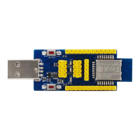
3.1 USB-Dongle
3.1.1 Functionality
•Atmel µC includes Segger USB-to-UART programmer (serial number on the backside)
•OTP cannot be damaged (fail-safe development)
•Runs with Dialog®’s Keil®Compiler projects
•Runs with Connection Manager
•Can be used for software development "on the fly"

PAN1740/1740A Bluetooth Module
3 Reference Design
Design Guide Rev. 1.0 Page 9
3.1.2 Schematic
3.2 Mother Board
3.2.1 Functionality
•Can be used with PAN1740/1740A Adapter Board
•OTP can be programmed
•Runs with Dialog’s Keil Compiler projects
•Runs with Connection Manager
•Can be used for software development "on the fly"
•Runs with Smart Snippets™ including Power Profiler
+3V3
391%
0.5R
+5V
1µ
4µ7
B3U-1000P
4k7
USB_A
BLM15BB121SN1
4µ7
+5V
10nF
100nF
BLM15BB121SN1
4µ7
Green 270
ATSAM3U2CA-CU
12MHz
6k8
10pF
18pF 18pF
391%
+3V3
10µ
10µ 100nF 100nF 100nF 100nF
10nF
0
+3V3
BLM15BB121SN1
100nF
+3V3
Green
Red
270
270
+3V3
150
150
100
100
150
nc
nc
nc
nc
1k
1k
nc
nc
+3V3
+3V3
100nF 100nF 100nF 100nF
4k7
4k7
4k7
100k
74LVC1G38DBV
4k7
+3V3
+3V3
+5V
0
W25X10CLUX
100nF
+3V3
EN
3IN
1
NC 4
OUT 5
IC3
TPS76933
R23
R27
C20
C19
S1
R21
DN 2
DP 3
GND@1GND@2
USB_GND 4
USB_VCC 1
X2
GND@3GND@4
L3
C21
C17
C15
L2
C16
LED
R26
VBG
A1
XIN
A2
XOUT
A3
PB17 A4
PB21 A5
PB23 A6
TCK/SWCLK
A7
VDDIN A8
VDDOUT A9
XIN32
A10
VDDCORE_1 D4
GNDUTMI
B2
VDDUTMI B3
PB10 B4
PB18 B5
PB24 B6
NRST
B7
TDO/TRACESWO
B8 TDI
B9
XOUT32
B10
DFSDP
C1 DHSDP
C2
GNDPLL
C3
PB14 C4
PB19 C5
PB22 C6
TMS/SWDIO
C7
NRSTB
C8
JTAGSEL
C9
VDDBU C10
DFSDM
D1 DHSDM
D2
VDDPLL D3
VDDCORE_2 E7
PB20 D5
ERASE
D6
TST
D7
FWUP
D8 PA11/PGMD3 D9
PA12/PGMD4 D10
PA29 E1
GND_1
F6
PA28 E3
PB9 E4
GNDBU
E5
VDDIO_1 F3
VDDCORE_3 B1
PA10/PGMD2 E8
PA9/PGMD1 E9
PA8/PGMD0 E10
PB1 F1
PB12 F2
VDDIO_2 F5
PA31 F4
VDDIO_3 E6
GND_2
E2
PB16 F7
PA6/PGMM2 F8
VDDCORE_4 F9
PA7/PGMM3 F10
PB11 G1
PB2 G2
PB0 G3
PB13 G4
VDDCORE_5 G5
GND_3
G6
PB15 G7
PA3/PGMNVALID G8
PA5/PGMM1 G9
PA4/PGMM0 G10
VDDCORE_6 H1
PB5 H2
PA27 H3
PA22/PGMD14 H4
PA13/PGMD5 H5
PA15/PGMD7 H6
PA18/PGMD10 H7
PA1/PGMRDY H9
PA2/PGMNOE H10
PB6 J1
PB8 J2
ADVREF J3
PA30 J4
PB3 J5
PA16/PGMD8 J6
PA19/PGMD11 J7
PA21/PGMD13 J8
PA26 J9
PA24 H8
PA0/PGMNCMD J10
PB7 K1
VDDANA K2
GNDANA
K3
AD12BVREF K4
PB4 K5
PA14/PGMD6 K6
PA17/PGMD9 K7
PA20/PGMD12 K8
PA23/PGMD15 K9
PA25 K10
IC1
VCC 8
VPP 14
SW_CLK 16
SW_DIO 18
P0.0
12 P0.1
11 P0.2
10 P0.3
9P0.4
6P0.5
5P0.6
4P0.7
3
P1.0
24 P1.1
23 P1.2
22 P1.3
21
N.C.
13 RST
2
GND 1
GND 7
GND 15
GND 17
GND 19
GND 20
GND A
GND B
GND C
GND D
MOD1 PAN1740
X1
R25
C18
C13 C14
R24
C6
C1 C2 C3 C4 C5
C11
R7
L1
C12
LED1
LED2
R19
R20
R12
R14
R13
R15
R1
R2
R8
R9
R10
R11
R16
R17
R18
C7 C8 C9 C10
R3
R4
R5
R6
1
24
IC2
3 5
IC2P
GND VCC
R22
VBUS
SWDIO
NRST
SWCLK
GND
SWO/TDO
P0.0
P0.1
P0.2
P0.3
P0.4
P0.5
P0.6
P0.7
P1.0
P1.1
P1.2
P1.3
R28
ERASE
TDI
GND_TP
/CS
1DO
2/WP
3GND
4DI 5
CLK 6
/HOLD 7
VCC 8
IC4 C22
VPP
SW_CLK
SW_CLK
SWDIO
SWDIO
RESET
RESET
CTS
CTS
RTS
RTS
RX
RX
TX
TX
M_RESET
M_RESET
V1.1
PAN1740ETUReference Design
DS-DG-1740ETU-
ForprogrammingSAM3U2C
A B Y
L L H
LLH
H
H
H
H H L
J-Link OB
www.segger.com
GND

PAN1740/1740A Bluetooth Module
3 Reference Design
Design Guide Rev. 1.0 Page 10
3.2.2 Placement
3.3 Adapter Board

PAN1740/1740A Bluetooth Module
3 Reference Design
Design Guide Rev. 1.0 Page 11
Schematic
3.4 Placement Recommendations
Antenna “Keep-Out Area”
Do not place any ground plane under the red marked restricted antenna area
in any layer! This would be affecting the performance of the chip antenna in a
critical manner.
Impact of Placement on the Antenna Radiation Pattern
The placement of the module, surrounding material, and customer
components has an impact on the radiation pattern of the antenna.
It is recommended to verify the perfect position of the module in the target
application before fixing the design.
VCC
PCI-E-64 PCI-E-64
VCC
VCC
0.1
VCC
n.c./0
VCC 8
VPP 14
SW_CLK 16
SW_DIO 18
P0.0
12 P0.1
11 P0.2
10 P0.3
9P0.4
6P0.5
5P0.6
4P0.7
3
P1.0
24 P1.1
23 P1.2
22 P1.3
21
N.C.
13 RST
2
GND 1
GND 7
GND 15
GND 17
GND 19
GND 20
GND A
GND B
GND C
GND D
MOD1 PAN1740
A1
A2
A3
A4
A5
A6
A7
A8
A9
A10
A11
A12
A13
A14
A15
A16
A17
A18
A19
A20
A21
A22
A23
A24
A25
A26
A27
A28
A29
A30
A31
A32
J1_A
B1
B2
B3
B4
B5
B6
B7
B8
B9
B10
B11
B12
B13
B14
B15
B16
B17
B18
B19
B20
B21
B22
B23
B24
B25
B26
B27
B28
B29
B30
B31
B32
J1_B
C1
R1
1
JP1 1
JP2
P0.0
P0.0
P0.1
P0.1
P0.2
P0.2 P0.3
P0.3 P0.4
P0.4 P0.5
P0.5 P0.6
P0.6 P0.7
P0.7 P1.0
P1.0
P1.1
P1.1
P1.2
P1.2
P1.3
P1.3
RST
RST
VPP
VPP SWCLK
SWCLK
SWDIO
SWDIO
ResetPINresistor isnot mountedifthemoduleisempty

PAN1740/1740A Bluetooth Module
3 Reference Design
Design Guide Rev. 1.0 Page 12
The following conditions must be met:
Keep this product away from heat. Heat is the major cause of decreasing the life of these
products.
Keep this product away from other high frequency circuits.
To download the design files, please refer to the download area on the product website
10.2.2 Product Information.

PAN1740/1740A Bluetooth Module
4 Run the Keil Project (Example)
Design Guide Rev. 1.0 Page 13
4 Run the Keil Project (Example)
The following requirements must be met:
SDK is installed.
USB-Dongle is installed.
Use always the latest release from Dialog website.
1. Open the Dialog SDK.
2. Open the proximity project example. The project is located in the following SDK folder.
3. Open Keil Compiler.

PAN1740/1740A Bluetooth Module
4 Run the Keil Project (Example)
Design Guide Rev. 1.0 Page 14
4. Configure the Flash Target: Flash > Configure Flash Tools). Choose Settings.
5. Click on the tab Debug (1).
6. Setup the Port to SW (2).
7. Click OK (3).

PAN1740/1740A Bluetooth Module
4 Run the Keil Project (Example)
Design Guide Rev. 1.0 Page 15
8. Click on the icon Build to build the target files.
9. Click on the icon Debug to run the debug session.
The proximity project has now been compiled and downloaded into the RAM of the
PAN1740/1740A ETU.
For more detailed information on project examples, please refer to Dialog’s
download website https://www.dialogs.com/. Recommended is the proximity
example as this is the most common profile.

PAN1740/1740A Bluetooth Module
5 Proximity Profile with two PAN1740/1740A USB-Dongles (Example)
Design Guide Rev. 1.0 Page 16
5 Proximity Profile with two PAN1740/1740A
USB-Dongles (Example)
This example uses Dialog’s SDK version 3.0.2.1.
The following requirement must be met:
Microsoft®Visual C++ 2010 Express –Freeware Compiler is installed.
Use always the latest release from Dialog website.
Receiver Configuration
1. Navigate to DA14580_SDK_3.0.2.1\dk_apps\keil_projects\proximity\
monitor_fe_usb.
2. Download the image proximity/monitor_fe_usb into the USB-Dongle.
For details please refer to 4 Run the Keil Project (Example).
3. Open Keil Compiler and compile this project.
Download the .hex-file
4. Start and stop the debug mode or load the .hex-file with the Connection Manager.
For debug mode using the Keil Compiler, be sure to check the Configure Flash Tool
setting described in 4 Run the Keil Project (Example).

PAN1740/1740A Bluetooth Module
5 Proximity Profile with two PAN1740/1740A USB-Dongles (Example)
Design Guide Rev. 1.0 Page 17
The Debug session must be stopped.
1. Open the folder Monitor Host Application in the SDK.
2. Open the project file host_proxm.sln with the Microsoft C++ Compiler.
3. Compile and run the software.
4. Determine the correct COM port using Windows®Device Manager and enter this port
number in the Proximity Host application (DOS window).
Transmitter Configuration
1. Download the image proximity/reporter_fe_usb into the USB-Dongle.
2. Open Keil Compiler and compile this project.
3. Start and stop the debug mode or load the .hex-file with the Connection Manager to
download the .hex-file.
4. Open the reporter host application.
5. Open the project file host_proxr.sln with the Microsoft C++ Compiler.
6. Compile and run the software.

PAN1740/1740A Bluetooth Module
5 Proximity Profile with two PAN1740/1740A USB-Dongles (Example)
Design Guide Rev. 1.0 Page 18
7. Determine the correct COM port using Windows Device Manager and enter this port
number in the proximity host application (DOS window).
The receiver side will show the connection status.
The USB-Dongles are connected with the proximity profile.
For more detailed information on Proximity Profile, please refer to Dialog’s
download website https://www.dialogs.com/.

PAN1740/1740A Bluetooth Module
6 Smart Snippets
Design Guide Rev. 1.0 Page 19
6 Smart Snippets
The following description describes the structure and the usage of Smart Snippets in a nutshell.
For more information as well as related documents, please refer to the Panasonic website
10.2.2 Product Information.
6.1 Program Structure
For details, please refer to the Smart Snippets help (Help/User Guide/Sleep Mode
Advisor).
6.1.1 Project and Port Selection
1. Open Smart Snippets.
2. Select a project, the virtual COM port, and the chip version to be able to control the
development kit.
When the application launches the first time, there will be no projects to select.
Click New to create a new project. The name should not contain any spaces
or special characters.
3. Select the chip version DA14580 and a virtual COM port which is assigned to the
connected dialog development kit.
4. Click Open to establish a connection to the development kit.
The software will show its default layout with a toolbar (Board Setup, UART Booter,
Power Profiler, Sleep Mode Advisor, OTP Programmer, SPI Flash Programmer,
EEPROM Programmer, and SPotA) and a few of these tools in the center of the dis-
play.

PAN1740/1740A Bluetooth Module
6 Smart Snippets
Design Guide Rev. 1.0 Page 20
6.1.2 Board Setup
The tab Board Setup in the toolbox has to be used before any other tool as it establishes a
communication with the development kit during the boot sequence and comes along with two
lists.
The upper list contains UART ports with its baud rate, which connect the FTDI chip version
“DA14580”. The other list selects the GPIO pin which enables 6.8 V for OTP programming.
6.1.3 UART Booter
The UART Booter enables to download application code directly into the RAM of the
“DA14580”to test its behavior in terms of power consumption for instance.
1. Click Browse (1) to select the desired code (.bin, hex., .ihex).
2. Click Download (2) and observe the Log (3) to handle the requested hardware reset.
3. Optional: Click Start Terminal (4) to receive debugging information via UART.
Note that an activated UART connection disables the OTP connection with the
result that the UART connection has to be closed to enable the OTP
connection and vice versa.
This manual suits for next models
14
Table of contents
Other Panasonic Wireless Module manuals

Panasonic
Panasonic PAN1780 Quick setup guide

Panasonic
Panasonic PAN1026A Guide

Panasonic
Panasonic INDUSTRY PAN9028 Quick setup guide

Panasonic
Panasonic PAN9026 User manual

Panasonic
Panasonic ET-WML100 User manual

Panasonic
Panasonic DNSK-P11 Manual

Panasonic
Panasonic DNSK-P11 User manual

Panasonic
Panasonic AJ-WM50P User manual

Panasonic
Panasonic PAN1026A Guide