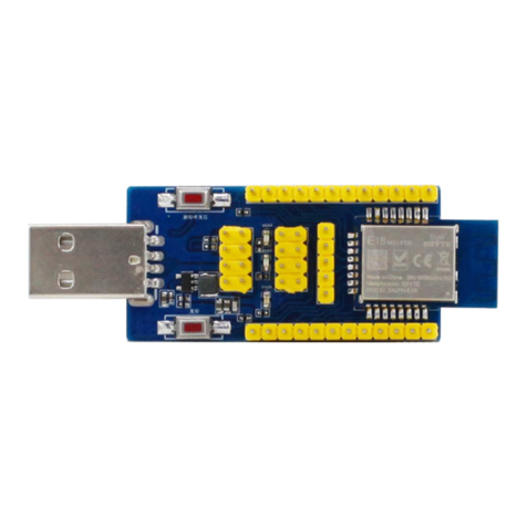
RF-WM-3235A1S
www.szrfstar.com V1.0 - Jun., 2020
Shenzhen RF-star Technology Co., Ltd. Page 5 of 28
Table of Contents
Wi-Fi Module List................................................................................................................................................................ 1
1 Device Overview............................................................................................................................................................. 2
1.1 Description............................................................................................................................................................ 2
1.2 Key Features....................................................................................................................................................... 2
1.3 Applications.......................................................................................................................................................... 3
1.4 Functional Block Diagram.............................................................................................................................. 3
1.5 Part Number Conventions.............................................................................................................................. 4
Table of Contents................................................................................................................................................................ 5
Table of Figures................................................................................................................................................................... 6
Table of Tables..................................................................................................................................................................... 7
2 Module Configuration and Functions...................................................................................................................... 8
2.1 Module Parameters........................................................................................................................................... 8
2.2 Module Pin Diagram......................................................................................................................................... 9
2.3 Pin Functions....................................................................................................................................................... 9
3 Specifications.................................................................................................................................................................12
3.1 Absolute Maximum Ratings.........................................................................................................................12
3.2 Recommended Operating Conditions .....................................................................................................12
3.3 Current Consumption Summary................................................................................................................12
3.3.1 Current Consumption Summary (2.4 GHz RF Band)...........................................................12
3.3.2 Current Consumption Summary (5 GHz RF Band)...............................................................14
3.4 TX Power Control for 2.4 GHz Band........................................................................................................16
3.5 TX Power Control for 5 GHz Band............................................................................................................17
3.6 WLAN Receiver Characteristics.................................................................................................................17
3.7 WLAN Transmitter Characteristics............................................................................................................18
4 Application, Implementation, and Layout.............................................................................................................20
4.1 Module Photos..................................................................................................................................................20
4.2 Recommended PCB Footprint....................................................................................................................20
4.3 Schematic Diagram.........................................................................................................................................21
4.4 Basic Operation of Hardware Design ......................................................................................................21
4.5 Trouble Shooting..............................................................................................................................................23
