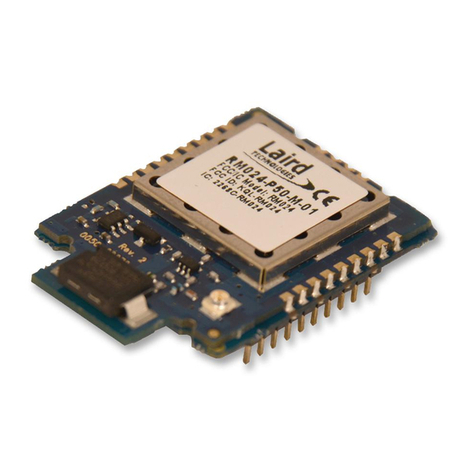
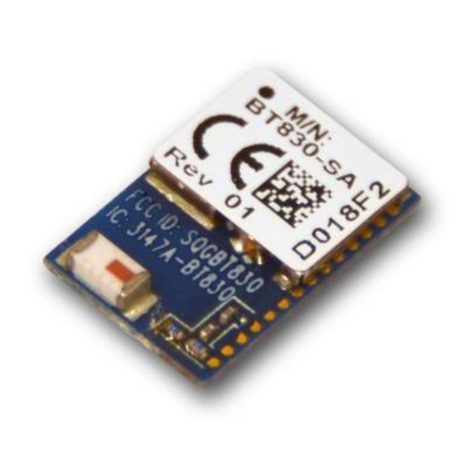
RF-Star RF-BM-BG22Ax Series User manual

RF-BM-BG22Ax
www.szrfstar.com V1.0 - Apr., 2021
Shenzhen RF-star Technology Co., Ltd. Page 2 of 23
Table of Contents
Table of Contents................................................................................................................................................................ 2
Table of Figures................................................................................................................................................................... 3
Table of Tables..................................................................................................................................................................... 3
1 Introduction ....................................................................................................................................................................... 4
2 Product Overview ........................................................................................................................................................... 5
2.1 Module Overview ............................................................................................................................................... 5
2.1.1 Module Pin Assignment...................................................................................................................... 6
2.1.2 Module Pin Function............................................................................................................................ 6
2.2 RF-BT02 Overview............................................................................................................................................ 8
2.2.1 Functions and Resources.................................................................................................................. 8
2.2.2 Adapter Modules ................................................................................................................................... 9
3 Preparation for Use......................................................................................................................................................10
3.1 Preparation of Hardware with RF-BT02..................................................................................................10
3.1.1 Pin Description between RF-BM-BG22Ax and RF-BT02....................................................10
3.1.2 Pin Wiring...............................................................................................................................................11
3.2 Preparation of Hardware without RF-BT02 ...........................................................................................12
3.2 Preparation of Software ................................................................................................................................14
4 Transparent Transmission Test by APP ...............................................................................................................16
4.1 Test by nRF Connect (Android)..................................................................................................................16
4.2 Test by BLE 调试宝 (Android) ....................................................................................................................18
5 Secondary Development ...........................................................................................................................................20
5.1 Downloads Address of Writer, DK, and SDK ........................................................................................20
5.2 Pin Description during Burning...................................................................................................................20
6 Trouble Shooting...........................................................................................................................................................21
6.1 Unsatisfactory Transmission Distance ....................................................................................................21
6.2 Vulnerable Module...........................................................................................................................................21
6.3 High Bit Error Rate ..........................................................................................................................................21
7 Revision History ............................................................................................................................................................22
8 Contact Us.......................................................................................................................................................................23
RF-BM-BG22Ax
www.szrfstar.com V1.0 - Apr., 2021
Shenzhen RF-star Technology Co., Ltd. Page 3 of 23
Table of Figures
Figure 1. Overview of RF-BM-BG22Ax series ............................................................................................... 5
Figure 2. Pin Diagram of RF-BM-BG22A1/A2/A3......................................................................................... 6
Figure 3. Function Area Distribution................................................................................................................... 8
Figure 4. Pin Diagram RF-BT02 (Left) and RF-BM-BG22A1/A2/A3 (Right) ....................................10
Figure 5. Pin Wiring between RF-BT02 and RF-BM-BG22A1/A2/A3.................................................12
Figure 6. Wire Connection of RF-BM-BG22A1/A2/A3..............................................................................12
Figure 7. Module Connected to USB-to-TTL Tool.......................................................................................13
Figure 8. Connect USB-to-TTL Tool to the Computer...............................................................................13
Figure 9. Wire Connection During Burning ...................................................................................................20
Table of Tables
Table 1. Pin Functions of RF-BM-BG22A1/A2/A3 ........................................................................................ 6
Table 2. Function Area Description..................................................................................................................... 9
Table 3. Table of Adapter Modules ..................................................................................................................... 9
Table 4. Pin Correspondence between RF-BM-BG22A1/A2/A3 and RF-BT02 ..............................10

RF-BM-BG22Ax
www.szrfstar.com V1.0 - Apr., 2021
Shenzhen RF-star Technology Co., Ltd. Page 4 of 23
1 Introduction
This is a user guide that helps you have a quick start on our module. There are two module test methods. The one is to
test the modules directly with the Dupont wire and the USB-to-TTL tool, the other is to test the module with the RF-star
RF-BT02 development board.

RF-BM-BG22Ax
www.szrfstar.com V1.0 - Apr., 2021
Shenzhen RF-star Technology Co., Ltd. Page 5 of 23
2 Product Overview
2.1 Module Overview
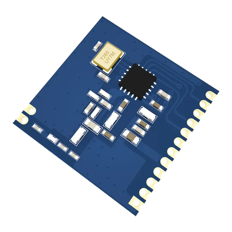
RF-BM-BG22Ax is an RF module based on EFR32BG22 series chip, one of Gecko family of SoCs from Silicon Labs,
with a 32-bit ARM® Cortex®-M33 core with 76.8 MHz maximum operating frequency. It integrates a 38.4 MHz / 76.8 MHz
crystal, a matching, an antenna matching, a low-pass filter and antenna options of a meander line inverted-F PCB
antenna and a half-hole interface. It supports Bluetooth 5.2 low energy, Bluetooth mesh, AoA/AoD and proprietary and
can be preprogrammed with a serial interface communication protocol for simple programming. It also has a range of
analog and digital interfaces such as PRS, ADC, UART, SPI, I2C, PWM, ISO 7816, IrDA, I2S, EUART and PDM. It
features low power consumption, compact size, robust connection distance, and rigid reliability. BG22A2 and BG22A3
reach up to 6 dBm TX power. 1.27-mm pitch stamp stick package for easy assembling and cost-effective PCB design.
Figure 1. Overview of RF-BM-BG22Ax series
Note:
1. RF-BM-BG22A1 and RF-BM-BG22A2 do not support AoA /AoD, and LE Long Range (125 kbps and 500 kbps) PHYs.
2. This user guide takes RF-BM-BG22A3 as an example to illustrate the testing methods.

RF-BM-BG22Ax
www.szrfstar.com V1.0 - Apr., 2021
Shenzhen RF-star Technology Co., Ltd. Page 6 of 23
2.1.1 Module Pin Assignment
Figure 2. Pin Diagram of RF-BM-BG22A1/A2/A3
2.1.2 Module Pin Function
Table 1. Pin Functions of RF-BM-BG22A1/A2/A3
Pin
Name
Chip Pin
Pin
Type
Description
1
EXT_ANT
-
-
External antenna interface
2
PB02
PB02
I/O
GPIO
3
PB01
PB01
I/O
GPIO
4
PB00
PB00
I/O
All parameters will be reset to factory settings after this pin is
set low for 5 s.
5
PA00
PA00
-
GPIO
6
PA03
PA03
I/O
The module input signal (Standard hardware flow control:
Clear To Send). When it is at a high level, the MCU serial port

RF-BM-BG22Ax
www.szrfstar.com V1.0 - Apr., 2021
Shenzhen RF-star Technology Co., Ltd. Page 7 of 23
is busy, and the module will not send data to the MCU serial
port. When it is at a low level, the module will send data to the
MCU serial port.
7
PA04
PA04
I/O
The module output signal (Standard hardware flow control:
Require To Send). When it is in high low, the module serial
port is busy, and the MCU is not allowed to send data to the
module serial port. When it is at a low level, the MCU is
allowed to send data to the module serial port.
8
PA05
PA05
I/O
Serial port TX
9
PA06
PA06
I/O
Serial port RX
10
GND
GND
-
Ground
11
RESET
RESET
-
Reset pin, active low (internal pull-up)
12
PA01
PA01
I/O
GPIO / SWCLK (connect JLink)
13
PA02
PA02
I/O
GPIO / SWDIO (connect JLink)
14
GND
GND
-
Ground
15
VCC
VCC
VCC
Power supply: 1.71 V~ 3.8 V, recommended to 3.3 V
16
PD01
PD01
I/O
Slave role (including Beacon) connection status indicator: in
low level during connection (LED always on)
17
PD00
PD00
I/O
Master role connection status indicator: in low level during
connection (LED always on)
18
PC00
PC00
I/O
GPIO
19
PC01
PC01
I/O
GPIO
20
PC02
PC02
I/O
GPIO
21
PC03
PC03
I/O
GPIO
22
PC04
PC04
I/O
GPIO
23
PC05
PC05
I/O
GPIO
24
GND
GND
-
Ground

RF-BM-BG22Ax
www.szrfstar.com V1.0 - Apr., 2021
Shenzhen RF-star Technology Co., Ltd. Page 8 of 23
2.2 RF-BT02 Overview
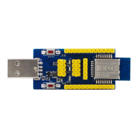
The RF-BT02 development board is a complete set of test products formed by a serial port module and a USB-to-TTL
baseboard for customer testing and development, which greatly reduces the difficulty of customers’ testing and
development.
2.2.1 Functions and Resources
The function area distribution is shown in Figure 3 and Table 2.
Figure 3. Function Area Distribution

RF-BM-BG22Ax
www.szrfstar.com V1.0 - Apr., 2021
Shenzhen RF-star Technology Co., Ltd. Page 9 of 23
Table 2. Function Area Description
Area
Name
Function
A
Module expansion area
The adapter modules are shown in Table 3.
B
Pin output area
All pins are accessible, which is convenient for tests.
C
USB-to-TTL area
USB-to-TTL function can be used as a USB-to-TTL tool when there
is no module.
D
3.3 V power supply area
Output voltage 3.3 V / 5 V
E
Button function area
Reset by pushing buttons.
2.2.2 Adapter Modules
Table 3. Table of Adapter Modules
EFR32BG22Cx
nRF52832/10
nRF52805
CC2640R2F
CC254X
RS02Ax-A/B
RF-BM-BG22A1
RF-BM-ND08
RF-BM-ND09
RF-BM-4044B2
RF-BM-S02
RSBRS02AA
RF-BM-BG22A2
RF-BM-ND08C
RF-BM-ND09A
RF-BM-4044B3
RF-BM-S02A
RSBRS02AI
RF-BM-BG22A3
RF-BM-4055B1L
RF-BM-S02I
RSBRS02ABR
RSBRS02ABRI
This user guide mainly introduces the use of the BG22Ax series modules.

RF-BM-BG22Ax
www.szrfstar.com V1.0 - Apr., 2021
Shenzhen RF-star Technology Co., Ltd. Page 10 of 23
3 Preparation for Use
3.1 Preparation of Hardware with RF-BT02
3.1.1 Pin Description between RF-BM-BG22Ax and RF-BT02
The following figure 4 is the pin diagram of RF-BT02 and RF-BM-BG22A1/A2/A3. Table 4 shows the pin correspondence
between the module and the development board. A1 ~ A4 pins of RF-BT02 correspond to pin 2 ~ pin 5 of the module,
A6 ~ A9 pins of RF-BT02 correspond to pin 7 ~ pin 10 of the module and A10 ~ A18 pins of RF-BT02 correspond to pin
16 ~ pin 24 of the module.
Figure 4. Pin Diagram RF-BT02 (Left) and RF-BM-BG22A1/A2/A3 (Right)
Table 4. Pin Correspondence between RF-BM-BG22A1/A2/A3 and RF-BT02
Outside Pins
of RF-BT02
Description
Inside Pins
of RF-BT02
Description
B1
GND
A1
PB02
B2
VCC
A2
PB01
B3
GND
A3
RESTORE (PB00)

RF-BM-BG22Ax
www.szrfstar.com V1.0 - Apr., 2021
Shenzhen RF-star Technology Co., Ltd. Page 11 of 23
B4
GND
A4
PA00
B5
BG22Ax CTS pin (PA03)
A5
RESET (RF-BT02)
B6
GND
A6
Module RTS pin (PA04)
B7
GND
A7
Module TX pin (PA05)
B8
GND
A8
Module RX pin (PA06)
B9
GND
A9
GND
B10
GND
A10
Connection status indicator of slave role (PD01)
B11
GND
A11
Connection status indicator of master role (PD00)
B12
GND
A12
PC00
B13
GND
A13
PC01
B14
GND
A14
PC02
B15
GND
A15
PC03
B16
RXD (CP2102)
A16
PC04
B17
TXD (CP2102)
A17
PC05
B18
GND
A18
GND
B19
GND
B20
VCC (5 V)
B21
VCC (3.3 V)
B22
RXD (CP2102)
B23
TXD (CP2102)
B24
RST
B25
SWD (J-Link)
B26
SWC (J-Link)
B27
VCC (3.3 V)
B28
GND
Remark: B5 is the GPIO PA03 of the module, and A5 is the RESET pin of the RF-BT02.
3.1.2 Pin Wiring
Prepare RF-BT02, RF-BM-BG22Ax, and USB to Type-C cable.
When using the BG22Ax series modules, the following pins need to be connected by Dupont wires: A7 and B22/B16
(TX → RXD), A8 and B23/B17 (RX → TXD). Remove the 0 R resistance in the red box at first.
When do the test, pls connect CTS to GND.

RF-BM-BG22Ax
www.szrfstar.com V1.0 - Apr., 2021
Shenzhen RF-star Technology Co., Ltd. Page 12 of 23
As shown in the figure below:
Figure 5. Pin Wiring between RF-BT02 and RF-BM-BG22A1/A2/A3
3.2 Preparation of Hardware without RF-BT02
1. As shown in Figure 6, the five key pins about testing PA03, PA05, PA06, GND, and VCC are accessible by DuPont
wires.
Figure 6. Wire Connection of RF-BM-BG22A1/A2/A3

RF-BM-BG22Ax
www.szrfstar.com V1.0 - Apr., 2021
Shenzhen RF-star Technology Co., Ltd. Page 13 of 23
Note: Be careful short-circuit. If you have a multimeter, it is best to check whether the adjacent pins are short-circuited
before powering on, as the short-circuit will easily damage the module.
2. As shown in Figure 7, the module is connected to the USB-to-TTL tool.
Module Pin
USB-to-TTL Pin
Pin 15 (VCC)
3.3 V
Pin 14 (GND)
GND
Pin 6 (PA03 CTS)
GND
Pin 8 (PA05 TX)
RX
Pin 9 (PA06 RX)
TX
Figure 7. Module Connected to USB-to-TTL Tool
3. As shown in Figure 8, connect the USB-to-TTL tool to the COM port of the computer, and check the port number of
the computer.
Figure 8. Connect USB-to-TTL Tool to the Computer

RF-BM-BG22Ax
www.szrfstar.com V1.0 - Apr., 2021
Shenzhen RF-star Technology Co., Ltd. Page 14 of 23
3.2 Preparation of Software
1. Install USB-to-TTL driver, the driver file is as follows:
2. After unzipping the driver file, according to the type of computer operating system, click to install the corresponding
program. Take the 32-bit computer operating system as an example, install the program shown in the following. (64-
bit operating system installs the program suffixed with * 64).
3. After installation, connect to the RF-BT02 and right-click on "Computer - Management - Device Manager - Port" to
see if the driver has been installed successfully. The successful installation is shown below (Repeat step 2 if it is
shown as a yellow exclamation mark).
4. Install and open the SSCOM5.13.1 software, this software will automatically identify the USB-to-TTL tool driver. The
software configuration is shown below. After the settings are correct, click to open the serial port.

RF-BM-BG22Ax
www.szrfstar.com V1.0 - Apr., 2021
Shenzhen RF-star Technology Co., Ltd. Page 16 of 23
4 Transparent Transmission Test by APP
4.1 Test by nRF Connect (Android)
1. Install nRF Connect (this APP can be found in the APP store):
2. Open nRF Connect, turn on cellphone Bluetooth, press “scanner”, press and hold the screen drop-down to search
surrounding devices. As shown in the following figure, there will be a Bluetooth device list broadcasting nearby.
After click on the BLE device you want to connect to, the connection process begins.
3. The operations after successful connection are shown in the following seven figures.
3.1. The process of transmitting transparent data: click "Nordic UART Service" (5), click "RX Characteristic" (6), and
send the transparent data "123456" (7, 8) from the mobile phone to the PC SSCOM5.13.1 tool, soon the PC
serial port tool receives the data (18), and the data sent can also be seen on the mobile phone (9). Click "TX
Characteristic" (10), and send the transparent data "12345678" (19) from the PC SSCOM5.13.1 tool to the "nRF
Connect". Soon the mobile phone will receive the data (11). The data sent can also be seen in the tool window
(20).
3.2. The process of transmitting AT commands:
Note: RF-BM-BG22Ax series modules need a "CRLF" as an end of the AT commands. AT commands with
"CRLF" cannot be input via the "nRF Connect".
If "nRF Connect" is used to send AT commands, the commands need to be in hexadecimal. Select the "BYTE
ARRAY" format (13) and add the 0D0A (it means the CRLF) at the end of every AT command to transmit
commands. The return value is also in hexadecimal. The hexadecimal return value needs to be decoded.
For example, "AT+NAME?", first convert AT+NAME? to hexadecimal: 41542B4E414D453F, and add 0D0A at
the end: 41542B4E414D453F0D0A (14), click "SEND" "(15), swipe right to see the data records of the operation

RF-BM-BG22Ax
www.szrfstar.com V1.0 - Apr., 2021
Shenzhen RF-star Technology Co., Ltd. Page 18 of 23
4.2 Test by BLE 调试宝 (Android)
1. Install APP “BLE调试宝” (this APP can be found in the APP store or ask RF-star to get the APK):
2. Open the "BLE调试宝", turn on cellphone Bluetooth, the operations are similar to "nRF Connect".
18
20
19

RF-BM-BG22Ax
www.szrfstar.com V1.0 - Apr., 2021
Shenzhen RF-star Technology Co., Ltd. Page 20 of 23
5 Secondary Development
5.1 Downloads Address of Writer, DK, and SDK
RF-BM-BG22A1/A2/A3 and other EFR32BG22Cx modules: Burn tool is J-Link, and the development environment is
simplicity IDE 4. Install the Bluetooth SDK package in simplicity ide 4 to obtain the SDK.
The development environment and SDK download address:
https://www.silabs.com/products/development-tools/software/simplicity-studio
5.2 Pin Description during Burning
Pls kindly refer to the pins when burning.
Figure 9. Wire Connection During Burning
This manual suits for next models
3
Table of contents
Other RF-Star Wireless Module manuals

RF-Star
RF-Star RF-WM-3235A1S User manual

RF-Star
RF-Star RF-BM-ND09A User manual

RF-Star
RF-Star RF-BM-2652P2 User manual

RF-Star
RF-Star RF-BM-ND08CI User manual

RF-Star
RF-Star RF-BM-S02 User manual

RF-Star
RF-Star RF-SM-1277B1 CC1312R User manual

RF-Star
RF-Star RF-WM-3200B1 User manual

RF-Star
RF-Star RF-BM-ND09 User manual

RF-Star
RF-Star RF-CC2540A1 User manual

RF-Star
RF-Star SimpleLink RF-BM-2652P1 CC2652P User manual