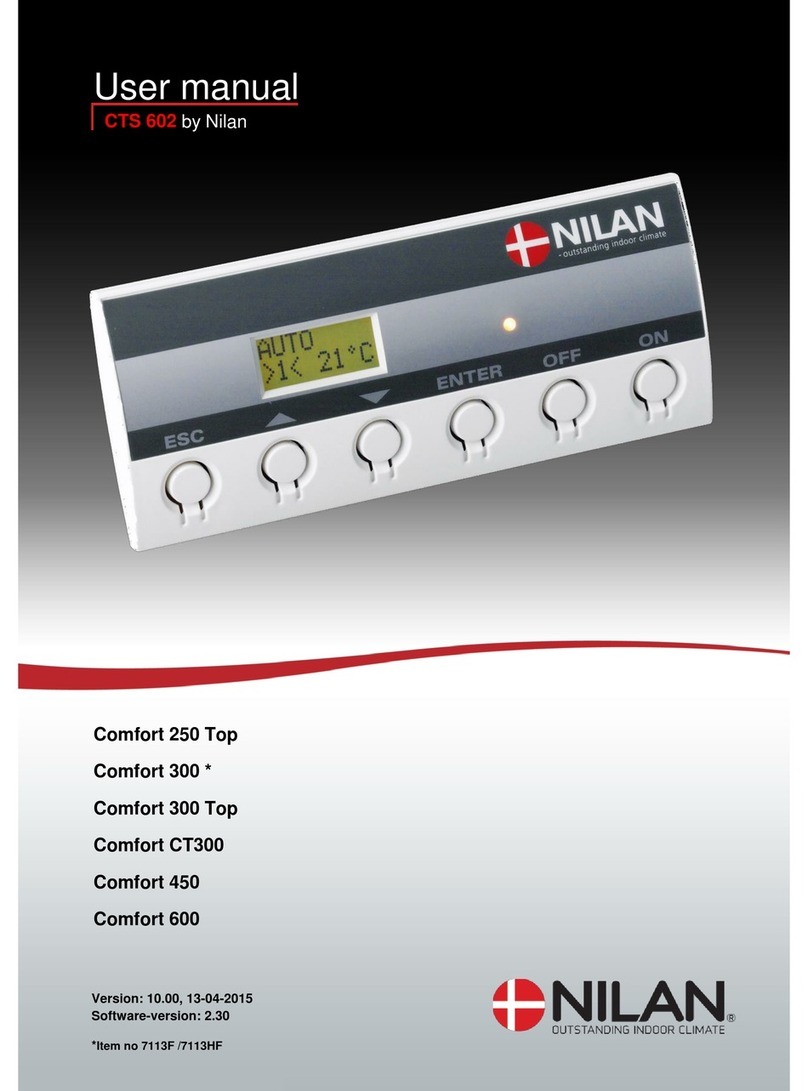
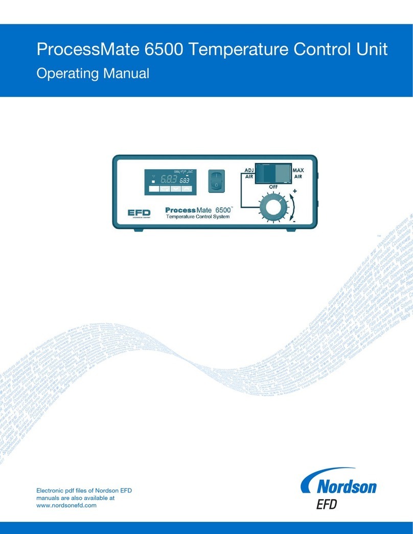
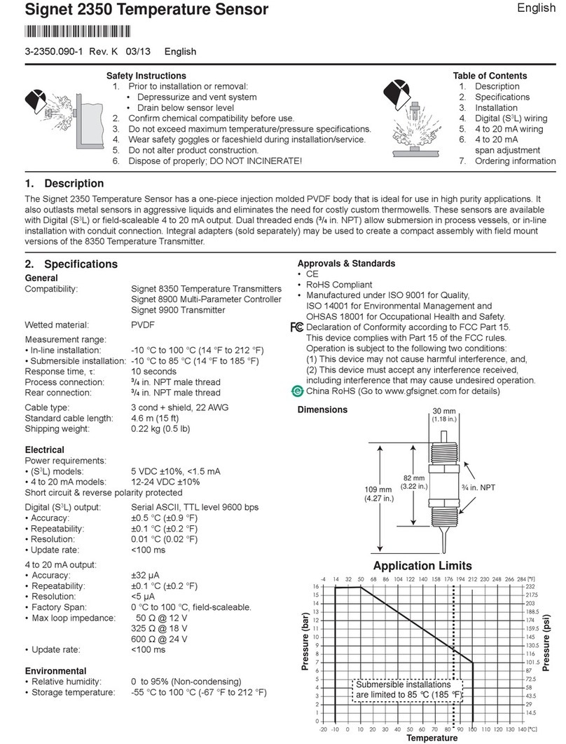
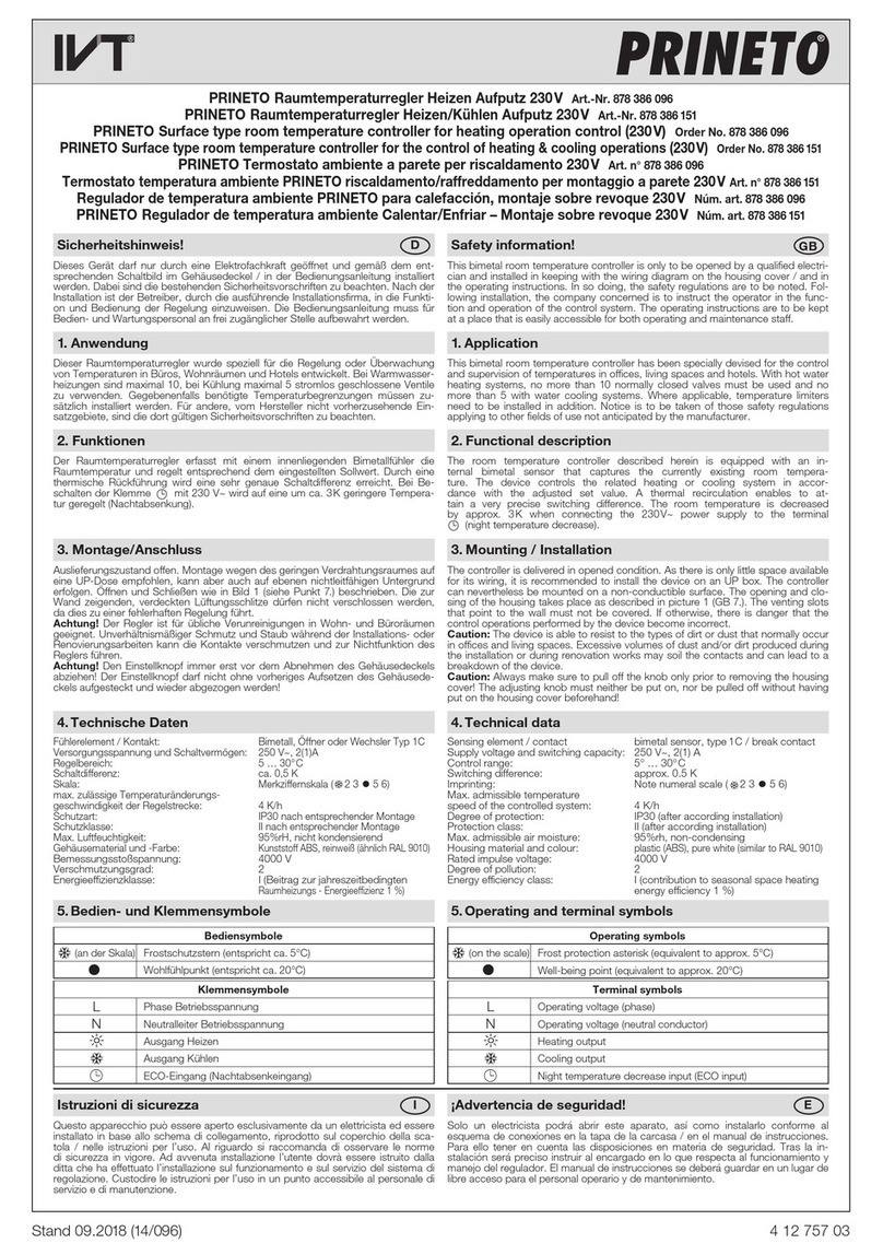
Hansung XH-KG55B User manual

R
X H - K G 5 5 B
R
X H - K G 5 5 B
XH-KG55B Temperature Controller
USER’S MANUAL
一 OVERVIEW
X H -KG55B is a in te l ligent te mpera t u re con t r o ller,
desig n ed by ob ject’s c h a rac te r is tics, contro l ling
programmed te mperature according to pr o c ess cu rs e
It s i mp l ifie s sys tem op er a tio n o f KG66 and decrea s e s
output in terface, to going to smaller and more
in t elligen t d irection A nd i t is st r o n g versat i le , fit for
controlled tempera ture which is le s s than 150
℃
, i e
wa s h ing mechanis m an d ele ctric hea t e r
二 MAIN SPECIFICTIONS
2.1
I/O interfaces
1 input channe l f o r temperature mea su r e me n t
3 output chann e ls wi th switching var i a b le o f which :
2 heating c o nt ro ls 1 cal l c o n tr o l
relay output : AC 2 4 0 V / 3 A
2 2 Temp erature control specif ications
te mp era ture measu r e me n t c o mponent
:
Pt100 platin u m t h e rmo -resistor
1

R
X H - K G 5 5 B
R
X H - K G 5 5 B
te mp era ture measu r e me n t r ange
: 000.0℃ ~ 153.0℃
te mp era ture contro l ra nge
: 030.0℃ ~ 150.0℃
te mp era ture contro l a ccuracy
:
sta ble error
≤ ±
1 2
℃
2.3
Programma le Funct i on s
programmab le p rocess No
.:
(0
~
9)
,
to tal 10
P
rogra mma ble p ro c e s s s teps of each p rocess is t e n
Each s tep is b e set objec t te mp era ture, gradi e n t and
iso t h e rm time
2.4
Temperature Control Method:
optimize self-adaptive method
2.5
Temperature p ara m e t ers setting range
object t e mp e r atu re
:(
030 0
~
150 0
) ℃
gradien t
:(
0 2
~
9 9
) ℃
/min
time of iso t h e rmic phase
:(
00
~
99
)
mi n
2.6
Programming Checkout Functions
Press
“△”
key to ch ec k w heth er se tt in g
parameters cor r e s p o n d with pa r a me t ers in the
process flo wcha r t or not
2.7
Safekeeping
(
1
)
Suddenly power cu t o ff , a r u n ning con tro ller
can continual l y ru n in retr ie vi n g the old proc ess step
data after p o we r is o n again
2

R
X H - K G 5 5 B
R
X H - K G 5 5 B
Reader’s Card
Dear Sir
,
Thank you for accep ting our p roduct.
Please fill in Re ader’s Card and se nd to us.
We ’d like to give you excelle n t s e rvice.
✄
Type of Controller
ty.
Da t e
Company
Conta c t Pers on
Te l.
Add
P.C.
Advice
Add:Building1NanhaiTiananCyberPark,FoshanGuangdong
Tel
:
0757-81230666 Fax
:
0757-81230666
1 4
(2) Du ring running probe is
broken,
th e con t r oller
calls 18 t i m e s , th e n it s t o p s
(3) When te mp e ra ture is hi g her than 150
℃ ,
th e
controller ca ll s a n d auto mat ica lly stops
2.8
Power Range
AC
(
180
~
250
)
V
、
50/60HZ Power consumption
≤3W
2.9
Dimension of Apparatus
W( 96) ×H( 96) × ( 100) mm
3
2.10
Dimension of Install ation
W( 92) ×H( 92) mm
2
2.11
Work Env i ronment
Te mpera t u r e
≤
50
℃
re l a tive humidi t y
≤
90
%
三 OPERATING GUIDE
3.1
Functional Keys
( 1)
RST
— —
— —— —
— —
When press it,”P” wi l l flash on pan e l In
runnin g state pu sh S TOP a t fi rs t, then push R S T
( 2)
PRG
— —
— —— —
— —
P r e s s i t t o g o t o p r o g r a m mi n g s t a t e
( 3)
RUN
— —
— —— —
— —
In rese t sta te press it to displa y
F*L*
F*L*F*L*
F*L*
, it
me a n s pro c e s s No & s t e p No A f ter en t e r
F*L*
F*L*F*L*
F*L*
it
sta rt t o run During r u n n i n g pr e ss i t to displa y
process No & s t e p N o for 3 sec s
3

R
X H - K G 5 5 B
R
X H - K G 5 5 B
(4)STOP
— —
— —— —
— —
In op erating s t a te press it to pause
controller
(5)
— —
— —— —
— —
(Page up
)
Press it to page u p d ata of each s te p
in sequence and me mo r ize paramete rs And ch e c k
program step b y s te p
(6)
— —
— —— —
— —(
((
(
Page down
)
Press it to pa g e do wn data of ea ch
ste p in sequen c e And c heck program i n n e g a tive s t ep
(7)
“
0
00
0~
~~
~ 9
99
9
”
— —
— —— —
— — (
((
(
number
)
Enter decimal number
0
00
0~
~~
~9
99
9.
..
.
(8)
— —
— —— —
— —
(
shif t ri g h t
)
Digital d i sp l ayin g place s h if ts
to w a rds righ t
3.2
Operat i ng Flowchar t
(1)program
F
FF
F
—
process No
.
L
LL
L
—
step No
.
i e pro c e s s No
.
F2,
step No
.
1
4
Problem Reason Troubleshooting
Can’t
program
Don’t push RST or
PRG key Don’t enter
finish code 00000000
in programming mode
Program again
Or turn on
controller to
program again
When
controller is
on, it’s in
isothermic
phase STOP
and RST key
can’t be
operated
Up-gradient rate and
down-gradient rate is
set 00 in
programming mode
Quickly push
STOP and RST
key, it can
return to
normal state
Check error
parameter and
program again
operation
error
Can’t run to
next step
Set data is unsuitable,
i e , set temp is 30
℃ ,
set time is 10
min But actual temp
is higher than 30
℃
in summer
Readjust
parameters
Abnormal
Don’t display
Press STAET key of
sampling dyeing
machine, but keys
can’t run rightly It
results in wrong initial
state
Cut off power
for 8-10
seconds, then
power on again
八 Service
A wa rran t y of time fo r o u r produc t i s one ye a r We
provid e ou r customers w ith cons i s te n t bes t a fter- s a le s
support If you h a ve an y p roblem, p lea s e don ’t hes i ta t e to
contact with u s
1 3
p r e s s
【
RST
】
to display P
press
【
P R G
】
to display F0L0
enter
【
F2
】
,press
【
►
】
to input
【
L1
】
enter data & next step
press
【
▲
】
memorize
ente r e n d co d e 00000000
press
【
RST
】
press
【
▲
】
memorize and page up

R
X H - K G 5 5 B
R
X H - K G 5 5 B
8.0 Trou leshooting
Problem Reason Troubleshooting
Display 000
℃
or 153
℃
P
robe circuit is short
or cut
Probe flex connected
wrongly
Check probe
and lines
Instable temp
during up-
gradient phase
Joins in probe line or
three-core insulating
line can’t be
connected or bad to
ground
Probe wet
Probe
Circu
it
Temp
inaccurate
which is up to
95
℃
Water come into
probe It become
vapor at high temp
Vapor influences
probe
Check and
connect probe
line again
Blow out water
in probe, then
seal and fix it
If necessary,
change new
one
Can’t increase
or decrease
temp when
controller runs,
but lights is on
Output is ok
AC contactor can’t
run or heated flex is
burnt out
Maintain
external electric
apparatus
Increase temp
slowly
Power of heated flex
is smaller
Val
ve
Increase temp
rapidly Temp
continually rise
in isothermic
phase
AC contactor is bad
or can’t run
change a new
one
1 2
( 2) Check Program
( 3) Run process(F2L1)
:
( 4) Re-run process after halt
ru n n i n g s t at e
pr e s s S TO P
pr e s s R N
( 5) Process Step Jump:
running state
press STOP
press
△
towards object process
push RUN twice
( 6) Process Parameters Correction:
d i s p l a y
P
PP
P
pr e s s P RG t o d i s p l a y
F0L0
F0L0F0L0
F0L0
enter
F
FF
F*
**
*L
LL
L*
**
*
press △ modify data press △
press
【
RST
】
5
display P
press
【
0
~
~~
~
9
】
to display F0L0
enter F*L*
p r e s s
【
▲
】
to check
press
【
RST
】
display P
press
【
R N
】
to display F0L0
enter F2 L1
press
【
R N
】
to start

R
X H - K G 5 5 B
R
X H - K G 5 5 B
3.3
Su routine Fun c t i o n
(1) Ru n n in g p a u se sub 161 0 0 0 0 0 & e nd sub 00000 0 0 0
,
th e c o ntrolle r s to p s and calls
(2)Temperatur e co r r e c ti o n
:
i e enter F9L9, see
corre ction func ti on a s belo w,
1 6 2 0 0 0 0 9 press
△
△△
△
to memo rize
subroutine No 0—positive correction
1—negative correction
Note
:
A
、
During run n in g pu sh
(
0
~
9
)
key to d i s p lay
corre cted te mp, i e + 5
℃
displa y 5
,
-5
℃
displa y - 5
B
、
If c h an ge new IC, r e-s e t temp cor rec tion program
If n eedn’t correct te mp , p l e ase set 16200000
C
、
Temperature deflection of KG55B is less than
±
0 6
℃
And temperature correction subroutine is 16200000 Only there
is old apparatus and bad probe, we have to correct temperature
The corrected temp value is used under 99
℃
after the controller
is in isotherm time 20mins It is right correction method that 6
bits standard resistor corresponds with standard temperature
Moreover, three-core insulating line can’t effect measured
temperature within 50 meters
6
Temperature (
℃
℃℃
℃)
))
)
PT100 resistor(
Ω
ΩΩ
Ω)
))
)
24 109 352
26 110 230
28 110 904
30 111 670
40 115 540
50 119 400
60 123 240
70 127 070
80 130 890
90 134 700
100 138 540
110 142 290
120 146 060
130 149 820
140 153 580
148 156 570
150 157 310
Start cont ro ll er to pre-heat f o r 3mins
Then calibrat e low p oint 50
℃
and high p o in t
130
℃
Pri mar i l y ca lib rate th i s two points and
th e n o thers Te mpe r a tu r e deflection o f each
point is les s than 0 6
℃ 。
11
0
~
9: max corrected temp is 9
℃

R
X H - K G 5 5 B
R
X H - K G 5 5 B
K G55 B B a c k Pan e l
diagram 2
7.0 Method of Temperature Cali ration
Repla c e P T100 with 6 b i ts standard re s i st or
Temperature (
℃
℃℃
℃)
))
)
PT100 resistor(
Ω
ΩΩ
Ω)
))
)
10 103 900
20 107 790
22 108 576
1 0
4.0 Operation Attention
(1)The last bit flashes in isotherm phase, not flashing in up-
gradient temperature phase It is to identify if setting
temperature is equal with real temperature or not
(2)
It is easy to s t ar t at a n y proc es s No ( F) & s te p
No (L)
(3) Handle a b n o rma l situation : If a b n ormal s i tu a tio n
happens i n opera t ion , c u t off power f or 5 s e c s
before the con t ro ller runs aga i n o r press R S T
(4) Opera ti o n o f keys s h o u ld be on for one se cond to
avoid er r o r
(5) When programming, set temperature had better to be
integer(set zeroes after decimal point)
(6) In ru n n i n g state p u s h S TOP to o nl y display te mp r a -
tur e o f dyeing ta n k
(7) If c o r r ec t in g process p a r a me ters, needn ’t shif t la s t
place to press
“
△
”
to pa g e up
.
( 8 )
We pr o vide cu s to mers with ge n e ral software
wi th o u t temperature correc t io n If c u st o me rs ha ve
special o r d e r, we can g ive you te mpe r a tu re
corre ction sof t w a r e
7
CALL
CALLCALL
CALL
PT100
HEAT 1 COM
HEAT 2
17
18
19
20
0
21
22
23
24
25
1
2
3
4
5
6
7

R
X H - K G 5 5 B
R
X H - K G 5 5 B
5.0 Explanation of Programming
i e process No
F2
F2F2
F2
,
ste p No
.
L0
L0L0
L0.
..
.
Diagram of Programming
No
act i o n set t i n g
te mp
(
℃
)
gr ad
(℃
/min
)
i s o t h e r m
t i m e
(
min
)
Process
No
F *
Step No
L*
1
2
3
4
5
6
7
8
press
RST
RSTRST
RST
press
PRG
PRGPRG
PRG
press
0
0 0
0~
~~
~9
9 9
9
press
△
set parameters
press
△
set end program
press
RST
RSTRST
RST
P
PP
P
F0L0
F0L0F0L0
F0L0
F2L0
F2L0F2L0
F2L0
000.0
000.0000.0
000.0
0 8 0
0 8 00 8 0
0 8 0.
..
.0
00
0
000.0
000.0000.0
000.0
000.0
000.0000.0
000.0
P
0.0
0.00.0
0.0
1
11
1.5
.5.5
.5
0.0
0.00.0
0.0
0.0
0.00.0
0.0
0 0
0 00 0
0 0
3 0
3 03 0
3 0
0 0
0 00 0
0 0
0 0
0 00 0
0 0
enter F*L*
enter F2
enter data
F2L1
enter data
F2L2,set 0
end
8
6.0 Diagram of KG55B Output Connection
KG 5 5 B F r o nt P a n el
Diagram 1
9
XH
-
KG
55B
DYEING CONTROLLER
TEMP (℃) *GRAD
(℃
/min)
*TIME
(min)
*
HEAT HOLD CALL RUN
R
FO
SHAN HAN
SU
NG AUTOMATION Co., Ltd.
R N
STOP
PRG
RST
0
~
~~
~
9
holding te mpe r at u re
80℃
for 30
END
up-gradient
1.5℃ /
mi n
amb i e nt temperatu r e
Table of contents
Popular Temperature Controllers manuals by other brands

Tzone
Tzone TZ-Tag06 user manual
Autonics
Autonics KPN Series User Manual for Communication
DirekTronik
DirekTronik LSN50v2-D20 user manual
Autonics
Autonics TM Series user manual
Viessmann
Viessmann Vitotrol 100 UTDB-RF2 Installation and service instructions

Middleby Marshall
Middleby Marshall 37626 Installation, programming and troubleshooting instructions
TE Technology
TE Technology TC-48-20 instruction manual
Autonics
Autonics TK Series User Manual for Communication
Sentera
Sentera RXTP Series Mounting and operating instructions
Gira
Gira KNX/EIB operating instructions

dixell
dixell XH360L operating instructions
Lutron Electronics
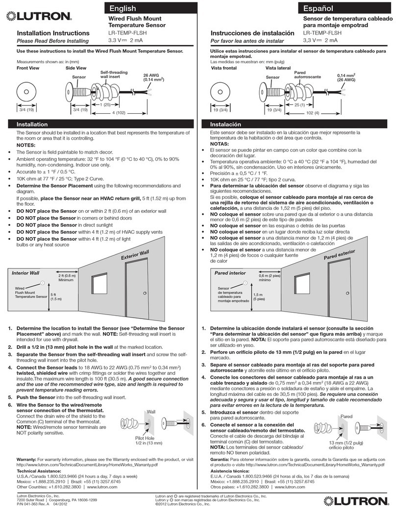
Lutron Electronics LR-TEMP-FLSH installation instructions
