nilan Compact S CTS 602 User manual

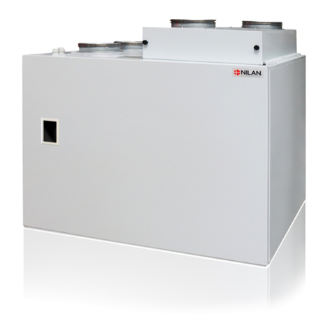
Comfort 250 Top
Comfort 300 *
Comfort 300 Top
Comfort CT300
Comfort 450
Comfort 600
Version: 10.00, 13-04-2015
Software-version: 2.30
*Item no 7113F /7113HF
User manual
User manual
CTS 602 by Nilan

Contents
Contents......................................................................................................................................... 2
List of figures.................................................................................................................................. 2
Introduction..................................................................................................................................... 3
System types.................................................................................................................................. 4
Temperature sensor overview......................................................................................................... 5
Control panel.................................................................................................................................. 6
Using the menus......................................................................................................................... 6
Menu overview ............................................................................................................................... 7
Menus......................................................................................................................................... 7
Operating status ............................................................................................................................. 8
Main menu.................................................................................................................................. 9
Show alarms............................................................................................................................. 10
Show data................................................................................................................................. 13
User options.............................................................................................................................. 14
User select 2............................................................................................................................. 15
Date and time ........................................................................................................................... 16
Weekly program........................................................................................................................ 17
Factory settings for the 3 weekly programs:.............................................................................. 17
Heating surface......................................................................................................................... 19
Cooling ..................................................................................................................................... 20
Humidity.................................................................................................................................... 21
CO2........................................................................................................................................... 22
Air exchange............................................................................................................................. 23
Air filter ..................................................................................................................................... 24
Temp. control............................................................................................................................ 25
Language.................................................................................................................................. 26
Filter change Comfort CT300........................................................................................................ 27
System dimensions ...................................................................................................................... 28
Accessories/spare parts ............................................................................................................... 33
List of figures
Figure 1: System types................................................................................................................... 4
Figure 2: Diagram illustrating sensor location for Comfort 250-600................................................. 5
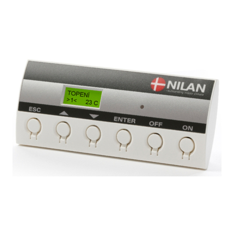
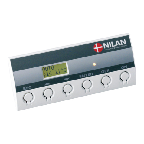
Figure 3: CTS 602 control panel..................................................................................................... 6
Figure 4: Menu overview ................................................................................................................ 7
Figure 5: Main menu....................................................................................................................... 8
Figure 6: Main menu options.......................................................................................................... 9
Figure 7: The "Show alarms" menu .............................................................................................. 10
Figure 8: The "Show data" menu.................................................................................................. 13
Figure 9: The "User select" menu................................................................................................. 14
Figure 10: The "User select" menu............................................................................................... 15
Figure 11: The "Date and time" menu........................................................................................... 16
Figure 12: The “Week program” menu.......................................................................................... 18
Figure 13: The "Heating surface" menu........................................................................................ 19
Figure 14: The "Cooling" menu..................................................................................................... 20
Figure 15: The " Humidity " menu................................................................................................. 21
Figure 16: The "CO2" menu.......................................................................................................... 22
Figure 17: The "Air exchange" menu............................................................................................ 23
Figure 18: The "Air filter" menu..................................................................................................... 24
Figure 19: The "Temp. control" menu........................................................................................... 25
Figure 20: The "Language" menu................................................................................................. 26
Figure 21: Filter change................................................................................................................ 27

May be subject to change Page 3 of 33
Introduction
Please check that the following documents have been supplied with the unit:
- Installation instructions
- Operating instructions for CTS 602 controls (this manual)
- Wiring diagram
The purpose of this manual is to provide a clear and concise description of the CTS 600 menus
and their possible settings.
The manual may contain functions and facilities which are not available on your system.
Unless otherwise stated in the titles, the descriptions apply to all systems listed on page 4.
When the display “shows” cooling”, the temperature of the inlet air is the same as the outside
temperature, and heat recovery is thus not performed.
PLEASE NOTE: If the system is damaged in any way, it must be inspected and repaired by
licensed personnel.
The system is delivered ready for use.
The factory settings are suitable for most user requirements and it should therefore not be
necessary to change any settings other than those found in the main menu.
The main menu is described on pages 8 and 9.

May be subject to change Page 4 of 33
System types
The controls are designed for use with the following systems.
The figure below describes the possibilities offered by the various models.
No.
Type
Heat recovery
Heating surface, water
Heating surface, electrical
Frost-protection of heating
surface
Cooling via by-pass damper
Defrosting
1
COMFORT 250 TOP
x
x
x
x
x
x
2
COMFORT 300
x
x
x
x
x
x
3
COMFORT CT300
x
x
x
x
x
x
4
COMFORT 300 TOP
x
x
x
x
x
x
5
COMFORT 450
x
x
x
x
x
x
6
COMFORT 600
x
x
x
x
x
x
Figure 1: System types

May be subject to change Page 5 of 33
Temperature sensor overview
Figure 2: Diagram illustrating sensor location for Comfort 250-600
Key to sensors described in figure 2:
T2 is the temperature sensor at the inlet ventilator (without heating surface).
T3 is the temperature sensor in the exhaust at the intake.
T4 is the temperature sensor in the outlet.
T7 is the temperature sensor in the inlet after the heating surface.
T8 is the temperature sensor in the outdoor air at the intake.
T9 is the temperature sensor of the heating surface.
T10 is the temperature sensor in the exhaust (accessory).
T15 is the temperature sensor located inside the CTS 602 control panel.
The temperature currently recorded by the various sensors can be seen in the VIEW DATA menu.

May be subject to change Page 6 of 33
Control panel
On the CTS 602 control panel, press:
- ESC to return to the previous menu
- qp to scroll upwards or downwards through the menus or to
adjust the setting of an activated menu option
- ENTER to activate a menu option
- ENTER to confirm a new menu option setting
- OFF to switch off the controls
- ON to switch on the controls
Figure 3: CTS 602 control panel
The yellow LED on the front of the control panel indicates the following:
Constantly lit: compressor in operation
Flashes: system in alarm condition
The control panel can display 2 lines of text, each containing 8 characters.
The upper line consists of explanatory text.
The lower line contains the setting or settings associated with the parameter described by the
explanatory text.
The text shown on the display remains "lit" as long as the system is connected to the power
supply. It will thus remain lit even if the system is turned off or if the control panel has not been
operated for some length of time.
Using the menus
To change a setting or function, the relevant menu must first be accessed by pressing por q.
To activate the required menu, press ENTER.
To change the setting of the required parameter, press and hold ENTER until the value flashes.
The setting can then be changed to the required value using pq.
To save the new setting, press ENTER.
When reading the following menu descriptions, it is a good idea to have access to the control panel
or menu overview.
If no buttons are pressed for one minute, the controls automatically return to the main menu.
If the controls return to the main menu during system configuration, any new data will be
automatically stored if they have been saved by pressing ENTER. It is always possible to continue
configuring the system by returning to the point reached.

May be subject to change Page 7 of 33
Menu overview
Menus
CTS 602 controls have 13 menus (if used for a system with cooling).
Usually, the main menu will be displayed on the control panel (i.e. the menu in the bold box in the
overview below). From here, it is possible to scroll through all the other menus using pq.
Opportunity for a low ventilating step at low outdoor temperatures.
Main menu: displays operating status.
Press ESC to return to the main menu.
Operating mode (heat, auto, cool), temperatures, fan speed, type of unit and
software version.
Alarm display and reset.
Alarm log containing the latest 16 alarms.
SHOW
ALARMS
SHOW
AUTO W/1
>2< 19°C
USER Options: exhaust, inlet, ventilation, OFF. The function selected is activated via a
switch or pressure.
10-09-13
TM.. 12:10 Date and time settings . The time and date must be reset if the system has been
without power for more than 24 hours. Summer and winter time must also be set
manually.
Weekly program can be set to ON or OFF . When the program is active , 1, 2
or 3 is displayed in the main menu.
SELECT
WEEK
PROGRAM
COOLING Option for choosing a higher ventilation level when the system is
cooling via open bypass valve.
AIR
EXCHANGE
AIR
FILTER
TEMP.
CONTROL
LANGUAGE
ENGLISH
The controls are factory set to activate a filter alarm every 90 days. The alarm
is reset in the VIEW ALARMS menu.
Setting the minimum temperature required in order for the bypass valve to
close. Maximum inlet air temperature can be set for a heating element.
Select the required language: English, German, French, Swedish,
Danish, Norwegian or Finnish.
HEATING The system has a heating surface installed. The heating surface can be
chosen ON/OFF. Frost-protection is still active when OFF is chosen.
SURFACE
DATA
HUMIDITY
CO2Possibility of high fan speed at high CO2–levels. The menu is only accessible
when the unit has CO2-sensors installed.
Offers the option to set a higher/lower fan speed at a high/low humidity level
USER User select 2 as user select
SELECT 2
Figure 4: Menu overview

May be subject to change Page 8 of 33
Operating status
Three parameters are shown in the main menu: operating mode, ventilation step and temperature.
These parameters determine operating status and are set by the user.
The main menu is shown on the display approx. 15 seconds after power has been connected,
allowing users to select the required settings.
By pressing ESC one or more times you will automatically return to the main menu.
AUTO */L/1
>2< 19°C
Ventilationstep
* : active user settings
1, 2, 3 : weekly program
active
L: low ventilation step at low
outdoor temperature
Operating mode: OFF
AUTO
COOL
HEAT
Required room temperature.
(5-30°C).
Main menu
Figure 5: Main menu
The required room temperature can be set by pressing ENTER once. The number beside °C will
begin to flash and the setting can then be changed using pq. Finally, confirm the new setting by
pressing ENTER.
As for systems without a post-heating element, the display shows the current room temperature.
Operating mode can be changed by pressing ENTER twice. The current mode will begin to flash,
allowing it to be changed using pq and confirmed by pressing ENTER. When the system is set to
“Auto”, the bypass valve opens and closes automatically, depending on the temperature setting.
“Cooling” means that the bypass valve is open, and “Heating” means that it is closed.
Ventilation step can be changed by pressing ENTER three times. The current ventilation step will
begin to flash, allowing it to be changed using pq and confirmed by pressing ENTER.

May be subject to change Page 9 of 33
Main menu
The main menu is displayed approx. 15 seconds after the power has been connected. Options that
flash are indicated by ” ”.
The options available on the main menu are shown in the figure below:
You will always return to the main menu if you press ESC one or more times.
On the CTS 602 control panel, press:
- ESC to return to the previous menu
- qp to scroll upwards or downwards through the menus or to
adjust the setting of an activated menu option
- ENTER to activate a menu option
- ENTER to confirm a new menu option setting
- OFF to switch off the controls
- ON to switch on the controls
AUTO
>2< ”19°C”
AUTO
”>3<” 19°C
”COOL”
>2< 19°C
”HEAT”
>2< 19°C
”AUTO”
>2< 19°C AUTO
”>2<” 19°C
ENTER ENTER
AUTO
>2< 19°C
AUTO
>2< ”5-30°C”
ENTER
When operating in
AUTO mode, the
controls automatically
call for cooling or
heating to maintain the
required room
temperature. A weekly
program can be used.
Heating to achieve the
set temperature. A
weekly program can be
used.
Cooling to achieve the set
temperature. Cooling via
by-pass damper only when
T8, outdoor air, is lower
than T3, exhaust. A
weekly program can be
used.
The indicated
ventilation step is for
exhaust air.
Main menu
Figure 6: Main menu options

May be subject to change Page 10 of 33
Show alarms
If an alarm condition occurs, the yellow LED on the CTS 602 control panel will begin to flash.
The SHOW ALARMS menu allows users to identify the alarm condition and the time at which it
occurred. Alarms can also be reset in this menu.
06-05-30
TI 11:32 ENTER
06-05-30
TI 10:28
STATUS
ALARM
T1 20°C
T2 20°C
T3 0,00
T4 0,00
OUT 1-8
00000000
OUT 9-16
00000000
OUT 17-24
00000000
ALARMLOG:
Is retained after
power has been
disconnected.
Contains the latest 16
alarms. AL 1 is the
most recent.
ALARM
DEFROST
SHOW
ALARMS ENTER ENTER
ALARM 19
FILTER
ALARM 8
FROST
ALARMLOG AL 1:
DEFROST
AL 19:
FILTER
AL 8:
FROST
ALARM LIST:
Displays 0-3 active
alarms.
The most recent and
most critical are
displayed first. The
list is deleted if power
is disconnected.
ALARMLOGDATA:
Data readings at the
time the alarm was
activated.
ENTERENTER
00-00-00
TI 00:00
Alarm reset: Alarms must be reset
individually. Only inactive alarms
can be reset. All alarms when
Alarm 0 None is displayed.
71
Figure 7: The "Show alarms" menu

May be subject to change Page 11 of 33
Alarm codes are given for specific alarm situations or where users are to be provided with
important information.
Alarms are grouped in the following categories:
C
Critical
Operation partially or totally discontinued as long as the alarm situation
persists.
W
Warning
Situation will become critical if not remedied within a reasonable period of
time.
I
Informative
Standard operation is not affected. The alarm is reset as soon as the user
acknowledges it.
Alarm
code
Category
Display text
Description/cause
Remedy
00
--
--
No alarm
01
C
HARDWARE
Fault in controls hardware.
Reset controls. Contact
service centre if fault
persists.
02
C
TIMEOUT
Warning alarm (W) has become a
critical alarm.
Make a note of the alarm
and reset.
Contact service centre if
alarm persists.
03
C
FIRE
Fire detecting thermostat.
Unit is stopped because the fire
detecting thermostat has been
activated.
If there has not been a fire
please contact service.
07
C
FROST
1) Frost-protection of heating
surface: the inlet air over the
heating surface is too cold
which can be caused because
the by-pass damper is open.
2) The water from the central
heating is too cold.
1) Close by-pass damper,
activate heating surface
and reset alarm.
2) Check that the heating
supply for the heating
surface is OK. Reset
alarm when fault has
been repaired.
08
C
FROST
One of the temperature sensors in
the unit is short circuit or defect.
Note the sensor and contact
service.
09
C
OVERTEMP
One of the temperature sensors in
the unit is disconnected or defect.
Note the sensor and contact
service.
10
C
OVERHEAT
Electrical heating surface has
been overheated due to lack of
airflow.
Check filters, air intake and
ventilators. Reset alarm.
Contact service centre if
system fails to operate
satisfactorily.
11
C
AIRFLOW
Lack of airflow in inlet. See alarm
code 10.
See alarm code 10

May be subject to change Page 12 of 33
Alarm
code
Category
Display text
Description/cause
Remedy
15
W
ROOM LOW
If room temperature falls below
10°C, the system will stop
operating in order to prevent
further cooling.
This could, for example, occur if
the house is unoccupied and the
heating system switched off.
Switch heating on and reset
alarm.
16
I
SOFTWARE
Error in controls software.
Contact service centre.
17
I
WATCHDOG
Error in controls software.
Contact service centre.
18
I
SET
System configuration has been
partially lost.
Can be caused by prolonged lack
of power or lightning.
The system will continue to
operate using standard settings.
Reset alarm.
Configure weekly program
as required.
Contact service centre if
system fails to operate
satisfactorily or as it did
before as subsettings may
have been lost.
(Such subsettings can only
be accessed by a service
technician.)
19
I
FILTER
The system is set to activate an
alarm for filter
inspection/replacement after a
specific number of days (30, 90,
180 or 360 days).
The default setting is 90 days.
Clean/replace filter.
Reset alarm.
21
I
SET TIME
Occurs during power failure.
Check weekly program
settings and reset if
necessary.
Reset alarm.
22
I
T AIR
The heating of the set
temperature cannot be reached.
Heating surface and system
cannot lift the temperature to the
required level.
Set a lower inlet
temperature. Reset alarm
27-57
C
TxSHORT
One of the temperature sensors
connected to the system has
short-circuited/is defective.
Short-circuited sensor = +99°C
Make a note of which sensor
(Tx) has short-circuited (e.g.
T1 short) and contact service
centre.
28-58
C
Tx OPEN
One of the temperature sensors
connected to the system has
been disconnected/is defective.
Disconnected sensor = -40°C
Make a note of which sensor
(Tx) has become
disconnected (e.g. T1
discon) and contact service
centre.
71
W
DFR EXCH
The maximum defrosting time for
the counter flow heat exchanger
has been exceeded. This could
be due to the fact that the system
has been exposed to very low
temperatures.
Contact our after sales
department if resetting the
alarm does not help.
If possible, inform the after
sales department of the
current working temperature
from the menu SHOW
DATA.
91
I
OPTIO
Accessories circuit board
Contact service centre.
92
i
PRESET
Error by writing or input of the
electrician’s adjustments
Contact service centre.

May be subject to change Page 13 of 33
Show data
Current operating data are displayed in the SHOW DATA menu.
The location of the various sensors is shown in figure 2 on page 5.
SHOW
DATA
EXHAUST
T3 40°C
STATUS
HEATING
PANEL
T15 20°C
INLET
T2 50°C
EXTERNAL
T10 9°C
Room temperature
recorded by T15
(sensor in CTS 600
control panel).
The software version
used by the system.
The software
version used by
the controls.
INLET
FLOW 2
SOFTWARE
1 2.21
EXHAUST
FLOW 2
OUTLET
T4 40°C
SOFTWARE
2 1.02
ENTER
FRESHAIR
T8 25°C
TYPE
COMFORT
T10 is an external sensor that can be
installed in an exhaust fitting in the
sitting area. T10 can be chosen as a
controlling room sensor in the service
menu.See the installation instruction
Sensor in the exhaust
air. T3 can be chosen
as a controlling room
sensor in the service
menu. See the
installation instruction.
For systems without
heating element, T2 is
shown. For systems
with heating element,
T7 is shown.
HUMIDITÉ %
100
CO2 588ppm
BYPASS
CLOSED
WATER
T9 25°C
Figure 8: The "Show data" menu

May be subject to change Page 14 of 33
User options
The menu CUSTOM OPTIONS overrides the operating mode of the main menu by activating an
external switch.
”VENTILAT”: There is a possibility here to run with a higher or lower speed on the air exhaust and
air inlet for a limited amount of time. The external pressure will activate the function. The function
has high priority.
”exhaust” and ”inlet”: These two options increase or reduce the velocity of the exhaust or inlet air
respectively for a limited period of time. The remaining functions of the operating mode remain
unaltered. An external switch activates the timer function.
Another external switch ensures that the fans remain at the desired ventilation level until the switch
is turned off.
”extend”: This option controls the velocity of the exhaust and inlet air and can be used to change
the temperature of the inlet air for a limited period of time. An external switch activates the timer
function.
“OFF”: Deactivates the external switch.
”ext offs”: Provides the possibility of choosing an afterflow time and changing the set point in
external rooms.
On the CTS 602 control panel, press:
- ESC to return to the previous menu
- qp to scroll upwards or downwards through the menus or to
adjust the setting of an activated menu option
- ENTER to activate a menu option
- ENTER to confirm a new menu option setting
- OFF to switch off the controls
- ON to switch on the controls
Time and speed must
be set in the same
way as described
under SELECT
EXTEND.
Required period in
which the selected
function is to remain
operative: stated in
hours and minutes.
Max 8 hours.
Switches user option
off.
Required ventilation
step: 1-4.
OFF allows the system
to be shut down via an
external switch.
TIME
FLOW
ENTER ENTER
TEMP
TIME 00:00
FLOW >4<
TEMP 23
ENTER
ENTER
ENTER
”00:00"
”OFF”
ENTER
ENTER
ENTER
°C
”>4<”
”23" °C
SELECT
SELECT
SELECT
SELECT
”EXTEND”
”INLET”
”EXHAUST”
SELECT
”EXTEND”
USER
SELECT
Required room temperature
(5-30°C).
T15 is the temperature sensor to
be used to control the system.
”EXT OFFS” ENTER
SELECT
.Choose the
afterrunning and
displacement of
the setpunkt, for
externak heating.
See SELECT
EXTEND
is an accessory and
via accessory pcb
the option is only possible
Option for an extra relay output
R8. R8
The temperature is added
or subtracted to/from the
set point shown in the main
menu.
”VENTILAT” ENTER
SELECT
Possibility to run at
a higher or lower
rate. High priority.
SELECT
”C HOOD”
RE1:NO contact for
controlling the hood
damper motor
Figure 9: The "User select" menu

May be subject to change Page 15 of 33
User select 2
User select 2 as user select. (Only if the option board is installed)
Time and speed must
be set in the same
way as described
under SELECT
EXTEND.
Required period in
which the selected
function is to remain
operative: stated in
hours and minutes.
Max 8 hours.
Switches user option
off.
Required ventilation
step: 1-4.
OFF allows the system
to be shut down via an
external switch.
TIME
FLOW
ENTER ENTER
TEMP
TIME 00:00
FLOW >4<
TEMP 23
ENTER
ENTER
ENTER
”00:00"
”OFF”
ENTER
ENTER
ENTER
°C
”>4<”
”23" °C
SELECT
SELECT
SELECT
SELECT
”EXTEND”
”INLET”
”EXHAUST”
SELECT
”EXTEND”
USER
SELECT 2
Required room temperature
(5-30°C).
T15 is the temperature sensor to
be used to control the system.
”EXT OFFS” ENTER
SELECT
.Choose the
afterrunning and
displacement of
the setpunkt, for
externak heating.
See SELECT
EXTEND
is an accessory and
via accessory pcb
the option is only possible
Option for an extra relay output
R8. R8
The temperature is added
or subtracted to/from the
set point shown in the main
menu.
”VENTILAT” ENTER
SELECT
Possibility to run at
a higher or lower
rate. High priority.
SELECT
”C HOOD”
RE7:NO contact for
controlling the hood
damper motor
Figure 10: The "User select" menu

May be subject to change Page 16 of 33
Date and time
The clock will continue to operate for at least 24 hours during power failure. If date and time
settings are lost, the "Set time" alarm will be activated.
Remember to set summer and winter time manually.
Options that flash are indicated by ” ”.
On the CTS 602 control panel, press:
- ESC to return to the previous menu
- qp to scroll upwards or downwards through the menus or to
adjust the setting of an activated menu option
- ENTER to activate a menu option
- ENTER to confirm a new menu option setting
- OFF to switch off the controls
- ON to switch on the controls
Is only displayed the
first time the clock is
set, Monday = 1.
06-05-30
TI 12.10 YEAR 06 ENTERENTER YEAR
”06"
MONTH
”05"
Seconds are zeroed when
minute is set.
MONTH 05
DAY 30
WEEK
DAY 2
HOUR 12
MINUTE 10
DAY
”30"
HOUR
”12"
MINUTE
”10"
ENTER
ENTER
ENTER
ENTER
ENTER
ENTER
ENTER
ENTER
ENTER
Figure 11: The "Date and time" menu

May be subject to change Page 17 of 33
Weekly program
The controls offer a choice of 3 weekly programs.
The controls are factory set to OFF.
In addition to these programmes it is possible to programme your own week programme which can
be one of the standard programmes with minor alterations.
Options that flash are indicated by ” ”.
Factory settings for the 3 weekly programs:
Program 1 is suitable for the working family
Program 2 is suitable for the non-working family
Program 3 is suitable for offices
Program
Week day
Function
Time
Ventilation
Temperature
Program 1
Monday -
Friday
1
2
3
4
6.00
8.00
15.00
22.00
3
1
3
1
21
21
21
21
Saturday -
Sunday
1
2
8.00
23.00
3
1
21
21
Program 2
Monday -
Sunday
1
2
8.00
23.00
3
1
21
21
Program 3
Monday -
Friday
1
2
7.00
16.00
3
OFF
21
21
MO 1 08.00
>1< 17°C
Time of program step activation.
If a program step should not be used
OFF should be chosen.
(OFF is located instead of 24.00)
Required room
temperature.
Week
day.
Program step.
6 program steps are
available each day.
Fan speed.
Weekly program settings

May be subject to change Page 18 of 33
On the CTS 602 control panel, press:
- ESC to return to the previous menu
- qp to scroll upwards or downwards through the menus or to
adjust the setting of an activated menu option
- ENTER to activate a menu option
- ENTER to confirm a new menu option setting
- OFF to switch off the controls
- ON to switch on the controls
Once settings have been made for
Monday , the values can be copied
to any other day the same settings
are to apply using in the copy
function.
System operation in
accordance with main
menu settings
”PROG 1"
MO1 06.00
>3 < 21°C
”CLEAR”
TU1 06.00
>3 < 21°C
MO TU
COPY
ENTER
ENTER
ENTER
”PROG 2"
MO2 08.00
>1 < 17°C
”PROG 3"
ENTER
ENTER
ENTER
ENTER
ENTER
ENTER ENTER
MO TU
”COPY” TU WE
COPY
TU2-6
SELECT
OFF ENTER ENTER
MO4-6
MO3 AUS
>1 < 17°C
PROG 1
WEEK
PROGRAM SELECT
”OFF”
SELECT
SELECT
SELECT
SELECT SELECT
Here it is possible to make your own
programme or adjust one of the
standard programmes. If there is more
than one function at the same time only
the last one is active.
Here it is possible to
chose one of the 3
standard programmes.
The 3 programmes can
be altered but not deleted.
The original programme
can always be found.
Here it is possible to delete all
user made programmes. The unit
will continue in AUTO mode
without any week programme.
Figure 12: The “Week program”menu

May be subject to change Page 19 of 33
Heating surface
The menu HEATING SURFACE is only accesssible when the system has a heating surface
installed and when the control has been set up to a heating surface in the SERVICE MENU
Options that flash are indicated by ” ”.
On the CTS 602 control panel, press:
- ESC to return to the previous menu
- qp to scroll upwards or downwards through the menus or to
adjust the setting of an activated menu option
- ENTER to activate a menu option
- ENTER to confirm a new menu option setting
- OFF to switch off the controls
- ON to switch on the controls
HEATING
SURFACE SELECT
OFF SELECT
”OFF”
SELECT
”ON”
ENTER ENTER ENTER
ENTER
When a heating surface is
installed T2 is replaced
with T7, which is the
sensor placed in the inlet
at the heating surface.
If you wish to disconnect the
heating surface this position should
be chosen.
The frost-protection is still active
and T7 is the active temperature
sensor for the inlet air.
Figure 13: The "Heating surface" menu

May be subject to change Page 20 of 33
Cooling
The Comfort range offers the ability to cool the air by opening a bypass damper. However, the
system will still recover a minimum of heat when in bypass mode.
The menu COOLING allows you to set the system to automatically run at a higher/the highest
ventilation level at high outside temperatures
Options that flash are indicated by ” ”.
On the CTS 602 control panel, press:
- ESC to return to the previous menu
- qp to scroll upwards or downwards through the menus or to
adjust the setting of an activated menu option
- ENTER to activate a menu option
- ENTER to confirm a new menu option setting
- OFF to switch off the controls
- ON to switch on the controls
COOLING VENTILAT
HIGH 2
ENTER ENTER
The options are OFF, 2,
3, 4.
VENTILAT
HIGH ”2" ENTER
Figure 14: The "Cooling" menu
Other manuals for Compact S CTS 602
11
Table of contents
Other nilan Temperature Controllers manuals
Popular Temperature Controllers manuals by other brands

MULTISPAN
MULTISPAN UTC-121P user manual

WIKA
WIKA Obsolete CF1M operating instructions

Nibe
Nibe HTS 40 Installer manual

Zhongshan Shangfang Instrument Meter
Zhongshan Shangfang Instrument Meter SF-105 quick start guide

dixell
dixell XR572C Installing and operating insructions

Oregon Scientific
Oregon Scientific THN132N user manual