Hantarex MTC 9000 Owner's manual

N R
X®
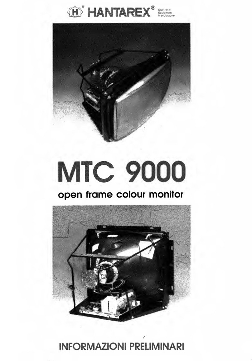
MTC 9000
open frame colour monitor
ADVANCE
INFORMATION
COMPATIBILITY
The
MTC
9000 has
been
created
bearing
in
mind
its
numerous
predecessor
that
are
still
in
daily
service,
so
that
its
technical
specification,
its
connexions,
and
its
mechanical
fixing points
are
all totally
compatible
with
its
antecedants,
thus
making
possible
any
variation
of
"crosses" with chassis,
picture
tubes
and
metal
structures
of
the
old
MTC
900
and
its
derivatives.
':

INTRODUCTION
The
principal
new
features
of
the
MTC
9000
are
as follows:
•
All
the controls which directly
affect
the display, horizontal frequency, vertical frequency, vertical
amplitude,
horizontal
amplitude,
horizontal
phase
and
vertical shift,
are
mounted
on a small
printed
circuit
board
connected
to
the
main
board
by
a
connecting
cable.
The monitor
is
supplied
complete
with a
connecting
cable
1.5 metres long,
which
permits
the
remote
mounting
of
the control
board
in
the
most
convenient
position for
any
particular
application.
This
"remote"
feature
is
exclusive to the Hantarex MTC 9000.
•Addition
of
two
connectors
to
each
deflexion yoke with inverted connexions which,
by
choice
of
connector,
permits
the easy inversion
of
the
image
both
vertically
and
horizontally for
certain
applications.
• Introduction
of
a novel
circuit
into
the
power
supply, which,
at
an
excessive
drop
in
supply
voltage,
transforms
the
stabilizer
circuit
into
an
anti-ripple
circuit
so
permitting
the use
of
the
monitor
outside the limits
of
stabilization.
•
Use
of
a
special
three-position switch
in
the
video
input
circuit
using close
tolerance
resitors,
permitting
the monitor
to
be
connected
to
input
signals varying
between
2
and
5 V p.p. without
the
introduction
of
tracking
errors,
which
would
otherwise
cause
undesirable
colour
changes.
• Introduction
of
a
new
integrated
circuit
(TDA
1670) for
vertical
deflexion
which
permits
the
achievement
of
a short
vertical
fly-back
time
(0.9 ms),
and
extends the use
of
the
monitor
where
a short vertical
blanking
period
is
required
.
• Introduction
of
a
new
integrated
circuit
in
the horizontal oscillator synchronization circuit, which,
among
otherthings,
provides for
more
accurate
intervention of the x-ray
protection
circuit
as required
by
the
principal
international safety
standars, such as F.D.A.,
the
Federal Drug Administration.
TECHNICAL
SPECIFICATION
TUBE
SIZE
POWER
REQUIRED
(excluding
degaussing)
14",
16"
and
20"
a.c.
current*
Voltage
Frequency
r.m.s. Current
d.c.
current**
Voltage
Current
115-142 V a.c.
50-400
Hz
at
lb
0 = 0.3 A
at
lb
1
mA,
= 0.7 A
155-200 V
d.c.
at
lb
0 = 0.3 A
at
ib
1
mA,
= 0. 7 A
*
IMPORTANT:
It
is
mandatory
to
use
an
isolating transformer with a
capacity
of
at
least 100 VA
built
to
local
safety standards.
Hantarex
declines
all responsibility for
eventual
damage
or
injury
caused
by
non
observance
of
the
above
standards.
•*
IMPORTANT:
It
is
mandatory
that
the
d.c.
supply
is
floating, viz. with
no
·
reference
to
earth
and/or
chassis (as
is
the
case
when
using
Hantarex Power Supply
US
300)
POWER
REQUIRED
Voltage
220 V
a.c
.
±20%
50-60
Hz
(degaussing) Frequency
Current 4 A for
approx
0.2 s
EARTH
SAFETY
CONNEXION
This
connexion
must
be
made
to the
metallic
structure
of
the
monitor which
is
not
separable
from the
electrical
earth.
SYNC.
AND
DEFLEXION
Sync. signals
Composite:
Amplitude
1.5 - 5 V
p.p.
Polarity
positive/negative
(switchable
by
switch on
p.c.b.)
Timing conforms
to
t.v.
standards±
10%
Separate:
Amplitude
1.5 - 5 V p.p.
Polarity
positive/negative
(switchable
simultaneously* **
by
switch on
p.c
.b.)
H width 1-10
us
H Freq. 15-16
kHz
V width 80-1000
us
V Freq. 45-70
Hz
H Phase with
standard
European t.v. signals the H
phase
control
permits a
displacement
of
the
image
(of
nominal
ampl
.)
of±4
cm
V Linearity errors <
3%
H Linearity errors < 3%
H
Amplitude
with
standard
European t.v. - signals
the
H
ampl
. permits
active
video
of
40-51
us
.
V
Amplitude
with
standard
European t.v. signals the V
ampl.
permits
active
video
of
16-19
ms
.
·
•*
The polarity
of
the
separate
synchronizing pulses
can
be
different
(between
H
and
V)
only by
modification
of
the
circuit
,
substituting
the
switch
by
a
bridge.
VIDEO
SIGNAL
Type
Polarity
Amplitude
Bandwidth
Rise/Fall Time
RGB
anal/TIL
compat.
positive, white (high-level)
2-5 V
p.p.
(by use
of
input
switch)
10
MHz
at
40 V
pp.
< 50
ns
at
70 V p.p.
NOTE
(a): The
MTC
9000
is
provided
with
both
horizontal
and
vertical
blanking
signals,
which
permits
the
use
of
the
monitor with
signals without
blanking.
(b): The three
RGB
video
amplifiers
are
d.c.
coupled:
there
is
thus
no
lower limit
to
the
pass
band.

PROTECTION
CIRCUITS
The
MTC
9000
is
provided
with the
following
protection
circuits:
a) Protection
against
excessive x-ray radiation.
This
circuit
is
obligatory
in
many
countries,
and
ensures that, with
the
worst
cathode-ray
tube
and
with a
breakdown
in
any
part
of
the
monitor, x-ray
radiation
will not
exceed
0.5 mR/h.
This
is
the international safety limit; however,
in
practice,
statistical measurements
made
on Hantarex
production
show
that
radiation
never
exceeds
0.1
mR/h.
b) Protection
of
the Power Supply Unit.
This
circuit protects the
power
unitfrom
accidental
short-circuit which
could
happen
during
installation or adjustment
of
the monitor.
DEGAUSSING
CIRCUIT:
Demagnetizing
time
5 s
Time
between
successive
Demagnetizations <30 min.
NOTE:
•
The
monitor must
be
left switched-off
between
successive de-magnetizations.
•
Normally
the
degaussing
circuit
operates
automatically
each
time
it
is
switched on; there
is
available
, on request,
an
accessory
comprising
a
connector,
a
cable
and
a push-button,
which
provides for
manual
operation
of
the
de-gaussing
circuit
.
BEAM
CURRENT
LIMITER:
FUSES:
NOTE:
Level
of
1imit
F1
F2
1
mA
approx
.
2
AT
(slow-blow)
3
AT
(slow-blow)
Fuse
F1
protects
the
whole
monitor with
the
exception
of
the
de-gaussing
circuit
.
Fuse
F2
protects
the
de-gaussing
circuit
only.
INSTALLATION
a)
Connect
to the
power
source as follows via
connector
CC:
Contacts 1-2 to
an
isolated source (see note)
of
alternating
current
at
128V, 50-400
Hz
capable
of
supplying
100VA.
Alternatively
one
may
use a
direct
current
supply
in
the
range
155-200.
V,
irrespective
of
polarity,
subject
to
its
being
isolated from chassis or earth, as, for
example,
one
of
the
Hantarex series
US
200/US 250/US 300. (see the note)
Contacts 3-4 to
the
mains supply
at
220-240 V a.c., 50-60
Hz.
b)
Connect
to the signal source as follows via
connector
CA:
Contact
1 positive
video
signal
BLUE
(B)
Contact
2 positive
video
signal
GREEN
(G)
Contact
3 positive
video
signal
RED
(R)
Contact
4
common
signal
earth
(GND)
Contact
5 vertical sync.
(V
SYNC)
(or no
connexion
if
using
composite
sync.)
Contact
6 horizontal or
composite
sync
(H
SYNC)
Important
The
use
of an isolating transformer
is
obligatory;
it
needs a power
capacity
of at least 1
OOVA
and
to
be
constructed to
meet
local safaty regulations. Hantarex accepts no responsability for any harm to persons
or
property resulting from non-observance
of
this
warning.
) Important
It
is
obligatory that the direct current source
shall
be
«floating», i.e. without any reference
to
earth
or
chassis,
such
as
in
the
case of the Hantarex
US
200/US
250/US
300.
c)
Connect
the
Earth wire to the
metal
structure as
prescribed
by
safety regulations.
d)
Set the sync. selector switch
(SW4)
to
adjust
the
monitor for
the
type
of
synchronizing signals
available;
SW4
functions
on
both
composite
sync.,
and
on
separate
sync. (simultaneously).
e)
Set
the
input selector
SW3
to
adjust the monitor to
accept
the
level
of
video
signal
available;
the
monitor functions
in
the
range
1.5 - 5 V p.p.
f)
If
necessary
is
possible
to
invert
the
image
(vertically
and
horizontally)
by
inserting the
connector
to
the
deflexion
yoke
in
position
CL
.
g)
If
it
is
necessary
to
adjust
the
controls on the
removable
control
panel
(either with the
panel
inserted
in
the chassis
or
connected
via
its
extension
lead)
the
image
characteristics
are
optimized
as follows:
H freq. -horizontal scan
frequency
Adjust within the
range
15.625 +/- 0.3
kHz
to
obtain
the
most
stable
display.
V freq. -vertical scan
frequency
Adjust from the
condition
where
the
image
scrolls
upwards
to
obtain
a
stable
display
.
V ampl. -vertical
scan
amplitude
Adjust for
optimum
display
height.
H ampl.- horizontal scan
amplitude
Adjust for
optimum
display
width.
H phase -horizontal
phase
Adjust for
correct
horizontal positioning
of
the display.
V
shift
-vertical shift
Adjust for
correct
vertical positioning
of
the
display
.

SETTING-UP
SPECIFICATION
regulation
or
control
test
signal measurement conditions point of point of value
measurement regulation
monitor
supply
voltage
grid
TP10
130 ± 3% V
d.c.
horiz. synchronization
grid
set
SW4,
bridge
TP6
screen
RV5
adjust
to
obtain
most
&
TP7
stable
display
unbridge
TP6
&
TP7
vert. synchronization
grid
check
50 & 60
Hz
screen
RV1
adjust
to stabilize
upward
scrolling
display
horiz. oscillator
supply
grid
TP12
12
v ± 5% V
d.c.
voltage
vert. oscillator
supply
grid
TP13
26 ± 5% V
d.c.
voltage
video
amplifier
supply
grid
TP1
24 ± 5% V
d.c.
voltage
video
output
stage
grid
SP11
190 ± 5% V
d.c.
supply
voltage
diode
modulator
grid
horizontal
amplitude
TP9
B3
adjust
for
maximun
*
RV4
set
to
minimun
G2
voltage
grey
scale
p.c.b.
ZG
TH2
'screen' set for 600 V
d.c.
(100:1
probe)**
black
level
grey
scale
set RV203, 204 & 205 to screen
RV?
adjust
to
make
the
min &
RV
201
& 202
half
darkest
band
disappear
and
the
adjacent
band
just v!sible
c.r.t. cut-off
none
faintly
illuminated
screen RV203, 204
eliminate
the
dominant
screen
by
G2 & 205
colour
by
adjustment
of
the
other
two
colours,
adjusting
brightness
white
level white field
KR
&
KG
RV
201
& 202
adjust
the
level
of
green
p.c.b.
ZG
and
red
cathodes
to
sarr.ie as
blue
focus
dot
medium
brightness screen
TH2
focus
adjust
for best focus
horizontal linearity
grid
screen
B1
adjust
width
of
first
square
equal
to
last
*The
maximun voltage at
TP9
can vary between approximately 34 and 50 V d.c. according
to
the type
of
c.r.t.
used.
**The position of the shaft of G2
is
marked
with
a reference point.
AN
R
x®
Electronic
Equipment
Manufacturer
(
50134
FIRENZE
-
ITALY
-30,
via
Riguccio
Galluzzi -tel.
055/4973
(20
linee
R.A.) -
telex
572341 Hantar-1 -
telefax
055/268486
Other manuals for MTC 9000
2
Other Hantarex Monitor manuals

Hantarex
Hantarex MTC 900 Instruction manual

Hantarex
Hantarex 10" User manual
Hantarex
Hantarex MTC90 User manual
Hantarex
Hantarex EQ/3 User manual

Hantarex
Hantarex MTC 900 User manual
Hantarex
Hantarex MTC-900E User manual
Hantarex
Hantarex MTC 9110 User manual

Hantarex
Hantarex MTC 9110 User manual
Hantarex
Hantarex MTC 9000 User manual

Hantarex
Hantarex MTC 9000 User manual
