Hanwell IM4772 iSense User manual

IM4772 –iSense
Instruction Manual

Doc No. IM4772-7
Page 2 of 14
iSense
Contents
1Introduction.................................................................................................................................................... 4
2Inventory........................................................................................................................................................ 5
3Product Description....................................................................................................................................... 6
3.1 Product Options....................................................................................................................................6
3.2 System Pre-requisites........................................................................................................................... 6
3.2.1 Hanwell Software.............................................................................................................................. 6
3.3 Wall Mounting Instructions....................................................................................................................6
3.4 Vehicle Mounting ..................................................................................................................................6
3.5 Adding iSense to Synergy .................................................................................................................... 7
3.6 Sensor operation ..................................................................................................................................7
3.7 Alarm Handling.....................................................................................................................................7
4Setting Up the iSense Hardware................................................................................................................... 8
4.1 Removing the Front Panel....................................................................................................................8
4.2 Connecting the Aerial ........................................................................................................................... 8
4.3 Connecting the Batteries ...................................................................................................................... 9
4.4 Connecting Vehicle Power Supply ....................................................................................................... 9
4.5 Operating Environment.........................................................................................................................9
5Sensor Input Wiring.....................................................................................................................................10
5.1 Connecting a Probe –Thermistor Example........................................................................................11
5.2 Connecting a Probe –JO91 Current Clamp Example........................................................................ 12

Doc No. IM4772-7
Page 3 of 14
iSense
Document History
Document Number: IM4772
Issue
No.
Issue Date
Changes
By
1
18 July 2010
First release.
MSH
2
23 December 2010
Adds information on redirector service and USB
configuration utility
MSH
3
28 September 2011
Add 3-channel thermistor connections
MSH
4
8 October 2014
Update for Synergy. Radiolog GPRS no longer
supported
CRB
5
18 September 2015
Update for Alarm Handling
RAB
6
11 November 2015
Mounting instructions added
RAB
7
30 May 2017
Vehicle usage instructions
CRB

Doc No. IM4772-7
Page 4 of 14
iSense
1 Introduction
Hanwell instruments offer a range of battery powered devices which can send their data to Synergy via GPRS
rather than low power radio. Data sent via GPRS is collected and stored on the IMC Remote Data Service,
from where your Synergy installation will retrieve it. Synergy then handles all data presentation and alarm
functionality in the normal way.
The devices log data on board and periodically send this logged data to the IMC Remote Data Service. This
send rate should normally be set low to save battery power, but in the event of an alarm the device will go into
a much faster transmission sequence. In the event of poor network coverage the device will retain data
packets and retry the send in due course
Synergy collects data associated with your iSense sensor(s), by making an outgoing TCP/IP connection to the
IMC Remote Data Service. As this connection is made to a standard HTTP port on the IMC Remote Data
Service, the system operates with the vast majority of network and Firewall configurations.
The device comes preconfigured with a SIM card fitted, so all that it is normally necessary to do is to connect
the sensor wiring (if required) and fit the battery.
A battery life of up to 3 years is achievable if the normal send rate is limited to once every 12 hours.
The actual desired send rate, logging rate and alarm levels will be sent from Synergy when first signal has
been received.
On first power up the device will send data every 5mins for 30minutes to verify correct operation.
It is also possible to have a remote radio system sending data to a CR2 which then transfers all of this
information via GPRS; in this configuration only one SIM card will be required.

Doc No. IM4772-7
Page 5 of 14
iSense
2 Inventory
Your iSense box should contain the following as standard:
1x iSense unit
1x Knuckle joint antenna (G205)
1x Battery Pack* (G213)
* If you have ordered an externally power unit then you will also either have a desktop power supply or 24V
DC truck power adaptor pre-fitted, instead of a battery.
WARNINGS
A battery pack must NOT be fitted when the external supply is used.
The desktop power supply is not rated for outdoor use, if you wish to use this outdoors then enclose
the whole in a suitable plastic or fibre glass enclosure
Use only the supplied mains adaptor with these devices.

Doc No. IM4772-7
Page 6 of 14
iSense
3 Product Description
3.1 Product Options
Extended antenna for low signal areas: AM36913
Standard input types include Thermistor, RH, 0...1V, 0...5V, 0...10V, 4...20mA, Current Clamps and Pulse
Counting.
Please ask for input options not listed above, as many sensor types can be accommodated.
3.2 System Pre-requisites
3.2.1 Hanwell Software
Synergy: Version 1.4.4 or above.
3.3 Wall Mounting Instructions
1. Use the three holes in the mounting box as a drilling template, ensuring that the keyhole is uppermost.
2. Screw the box mounting box to the wall.
3. Insert the iSense unit into the mounting box.
3.4 Vehicle Mounting
IMC strongly recommend that the iSense is mounted inside the vehicle body; in any case, the iSense unit
needs to be protected from extremes of temperature changes, and wind force.
The iSense unit has 4 mounting holes, adjacent to the lid fixing screw holes on each corner; these are
accessed by removing the lid; the unit should be mounted with 4mm diameter bolts, or equivalent self-tapping
screws.
Where radio reception inside the vehicle is likely to be affected by bodywork etc. use a GSM aerial mounted
externally to the vehicle body, this connects to the brass coloured aerial connector mounted on the iSense
side, (do not use excessive force tightening the aerial connection, finger tight is adequate).
See Connecting Vehicle Power Supply for vehicle power connection details.

Doc No. IM4772-7
Page 7 of 14
iSense
3.5 Adding iSense to Synergy
The iSense must be added to Synergy using the Family Type iSense; see Synergy User Manual ‘Adding
Sensors’, for full details on adding sensors to Synergy.
Note: Do NOT try to use the iSense with RadioLog, and do NOT attempt to configure the iSense with the
legacy iSenseConfig Utility or iSense USB Configurator.
3.6 Sensor operation
The devices will log data on-board at the pre-set log interval, and in due course send these to the IMC
Remote Data Service. This send process will occur under the following circumstances:
After the ‘SendInterval’
OR 300 logged points are available
OR 12hours has elapsed
OR the measurement is in alarm
In the event of communications failure the device will buffer up to 250k of data and gradually send this after
communications is restored, and in reverse time order. If and when this happens at each wake up the device
will send its current packet plus the most recent three packets whose sending was not successful
If the measurement goes into alarm then the unit will start to transmit every 15minutes for a period of up to 2
hours. At this time it will revert to its programmed behaviour. No alarm will be re-triggered until three logs have
been within the alarm limits.
The device sends its battery voltage with each message; this can be viewed via Synergy.
3.7 Alarm Handling
It is possible to set level alarms on each individual iSense channel. It is important to remember that as the
device only calls in, then these values can only be changed on a standard connect cycle. This cycle will
happen at some time later –possibly many hours later –after the Synergy change.
Prior to an alarm the sensors are sampled at the nominal interval and sent periodically, but if an alarm
condition is detected it will transmit this within the following 4 minutes. Thus the maximum iSense response
time to an alarm is (nominal logging interval +4 min).
Assuming that the GSM network is up and running perfectly then there will be up to a further 8 minutes before
it appears on screens because of redirector and Synergy delays. Any provider network delays are outside of
our control and may be added to this time.
The device will continue to send data rapidly for 2 hours (every 15 minutes) after the initial transition and then
revert to normal mode. If the alarm condition persists then this will start the sequence again.
To cope with the system delays you should set the alarm reactivation time on the PC to a minimum of
30 minutes, and not manually reset it prior to this or you risk seeing the same alarm reported twice.

Doc No. IM4772-7
Page 8 of 14
iSense
4 Setting Up the iSense Hardware
4.1 Removing the Front Panel
The iSense unit is fastened by four screws that are situated in each corner on the front of the device. By using
a screwdriver to unscrew these four screws the front panel will lift off from the rest of the device. See Figure 1
below for details:
Figure 1 iSense GPRS Unit Front Panel
Once the front panel has been removed the battery pack will be visible on its reverse side. This now leaves
the back panel open and the iSense circuit board accessible.
4.2 Connecting the Aerial
There are two types of aerials which can be attached to this unit, either the extended or the knuckled joint.
Choose one that will better suit the environment that this device will be situated in and simply screw it into the
Aerial connection found on the top of the iSense. The Aerial should be positioned to ensure a good RF signal,
(do not use excessive force tightening the aerial connection, finger tight is adequate).

Doc No. IM4772-7
Page 9 of 14
iSense
4.3 Connecting the Batteries
The battery pack is held in place against the front panel of the iSense unit by two Velcro fasteners. Simply
peel the Velcro apart to release the battery pack (see Figure 2). A new pack can then be fastened in place
using the same Velcro sleeves.
The connection of the new battery pack to the iSense circuit board is done by inserting the battery plug from
the pack into the battery terminal, located on the circuit board.
Figure 2 Connecting the Batteries to the iSense Circuit Board
4.4 Connecting Vehicle Power Supply
The vehicle power supply connects to terminals 7 and 8 on the PCB connector inside the iSense unit.
Unscrew and remove the lid, connect the vehicle supply cable as below:
Yellow/Red wires, iSense +ve, connect to terminal 8
Blue/Green wires, iSense -ve, connect to terminal 7
Black/Blue wires, Vehicle –ve, connect to vehicle negative
Brown wire, vehicle +ve, connect to vehicle positive
Vehicle power should be sourced from as clean a supply as possible; the inline fuse is 250mA, input range is
+15V to +30V.
If required, replacement fuse is IMC part number G097, 20MM 250mA anti surge fuse.
4.5 Operating Environment
Maximum temperature ranges are:
Operating range with battery 0C to +40C.
Operating range with external power supply -20C to +55C.
Operating range with vehicle power supply 0C to +55C.
Storage temperature range, (without battery), -40C to +80C.
Note: The above ranges apply to the iSense unit itself, these do not apply to input probes, check probe
operating ranges as these will vary from probe to probe.

Doc No. IM4772-7
Page 10 of 14
iSense
5 Sensor Input Wiring
In the following section of this document a table has been included which contains a list of all the possible
input sensor types that can be connected to the iSense device. The majority of these sensors will be
connected via the sensor connection terminal (JP1). This terminal has six pins with pin 1, 3 and 5 being
positive, while 2, 4 and 6 are negative.
The Thermistor/RH sensor differs from the other devices as it connects to the 5 Pin Lemo socket (JP5). Both
of these areas of the iSense are shown in Figure 3 below.
Input Type
JP1 Pin Connection
Channel Type
1 channel pulse counter
Pin 1(+) & 2(-)
channel 1
2 channel pulse counter
Pin 1(+) & 2(-)
channel 1
Pin 3(+) & 4(-)
channel 2
1 channel pulse & sync
Pin 1(+) & 2(-)
sync
Pin 3(+) & 4(-)
channel 1
2 channel pulse & sync
Pin 1(+) & 2(-)
sync
Pin 3(+) & 4(-)
channel 1
Pin 5(+) & 6(-)
channel 2
Single Thermistor
Pin 3(+) & 4(-)
channel 1
Dual/Triple Thermistor
Pin 1(+) & 2(-)
Pin 3(+) & 4(-)
channel 1
channel 2
Pin 5(+) & 6(-)
channel 3
Current Clamp
Pin 1(+) & 2(-)
channel 1
Pin 3(+) & 4(-)
channel 2
Pin 5(+) & 6(-)
channel 3
Thermistor and Digital
Pin 1(+) & 2(-)
Pin 3(+) & 4(-)
Thermistor
Digital
Input Type
JP5 Pin Connection
Channel Type
Thermistor/RH
5 Pin Lemo
n/a
Figure 3 Sensor Input Wiring

Doc No. IM4772-7
Page 11 of 14
iSense
5.1 Connecting a Probe –Thermistor Example
For this example a thermistor probe is used to demonstrate how to connecting one of the accompanying
devices to the unit.
The thermistor probe can be found coiled with the metal probe attached to one end and two exposed wires
(white and red) on the other.
Figure 4 Loosening the Input Glands
Figure 5 Opening Terminals 3 and 4
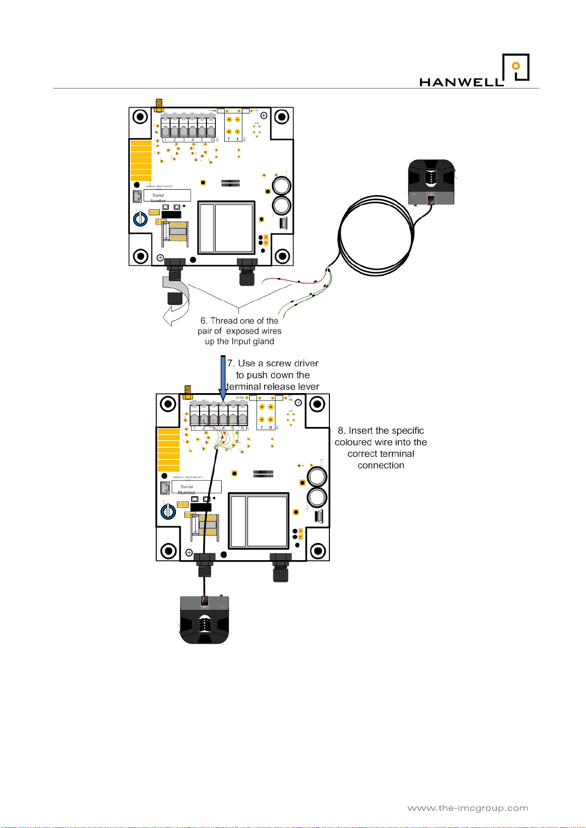
To attach the probe to the circuit board, loosen the input glands (Figure 4 above), thread the exposed wires up
the gland until there is enough length for the wire to reach the top of the circuit board, tighten the gland.
Using a screwdriver, press down on the terminal release lever to open terminals 3 and 4 and thread in to
these openings the red and white (respectively) exposed wires (Figure 5). If another probe is needed to be
fitted then follow the same procedure but open terminals 5 and 6 and thread in the new red and white wires.

Doc No. IM4772-7
Page 12 of 14
iSense
5.2 Connecting a Probe –JO91 Current Clamp Example
For this example a current clamp is used to demonstrate how to connect one of the accompanying devices to
the unit (Fig. 6). A J091 is illustrated. Other (DC only) clamps are connected in a similar manner.
Channel No.
+ve
-ve
1
Green (pin1)
Black (pin2)
2
Red (pin3)
White (pin4)
3
Yellow (pin5)
Blue (pin6)
Any unused pairs should be twisted together.
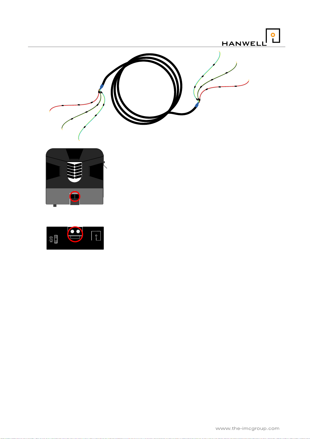
J091 OUTPUT
www.hanewll.com J091 OUTPUT
www.hanewll.com
1. Lift the latch found on the side
of the unit and open the
released clamp.
2. Thread the single core cable
through the middle of the clamp
and then secure the latch.
Figure 6 Connecting a JO91 –1
Doc No. IM4772-7
Page 13 of 14
iSense
Figure 7 Connecting a JO91 –2
V093
J091 OUTPUT
www.hanewll.co
m
HANWELL
MONITORING & CONTROL
-+
Amperage Range
120
60
30
0-5VDC
3. Thread one of the V093 coloured wires into the correct output
terminal situated on each of the clamps to be used.
4. The bottom of the clamp indicates which side of the terminal
is positive/negative. Use this in conjunction with the table on
page 29 to connect the correct coloured VO93 wire.
5. Use the screws found here to tighted the threaded wire to the clamp.
Ch. 1
Ch. 2
Ch. 3
Ch. 2
Ch. 1 Ch. 3
Doc No. IM4772-7
Page 14 of 14
iSense
Figure 8 Connecting a JO91 –3
Table of contents


