Hanwha HEBS II User manual

HEBSⅡ
User Guide
Electronic Blasting System

1. Before Use
1.1 Warnings 6
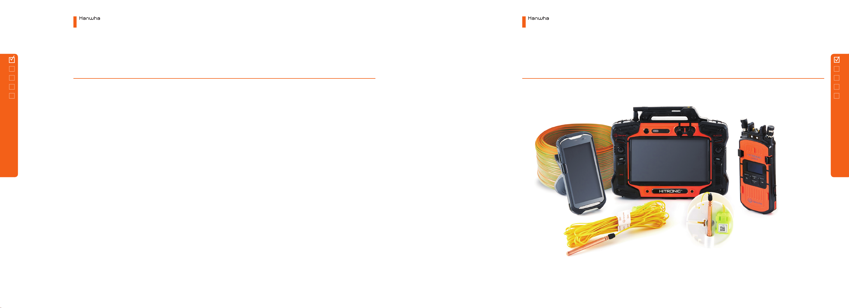
1.2 HEBS-II Components 7
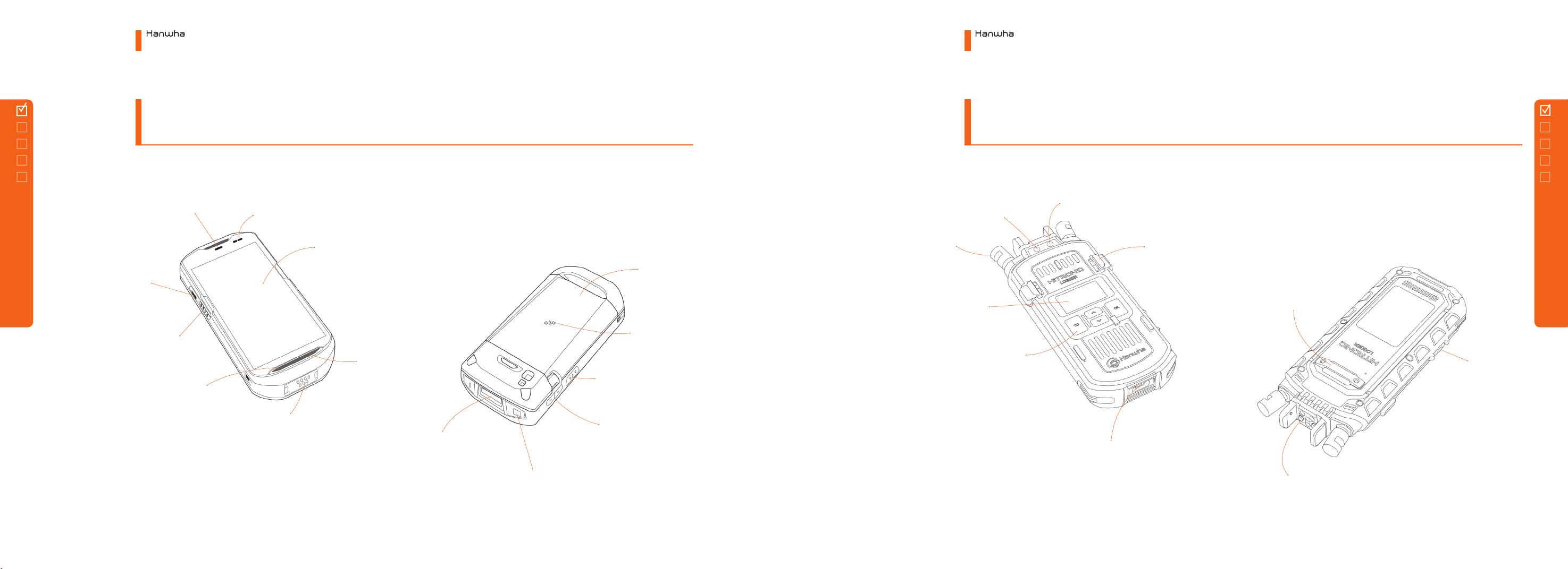
1.3 Each part name and role
1.3.1
Planner 8
1.3.2
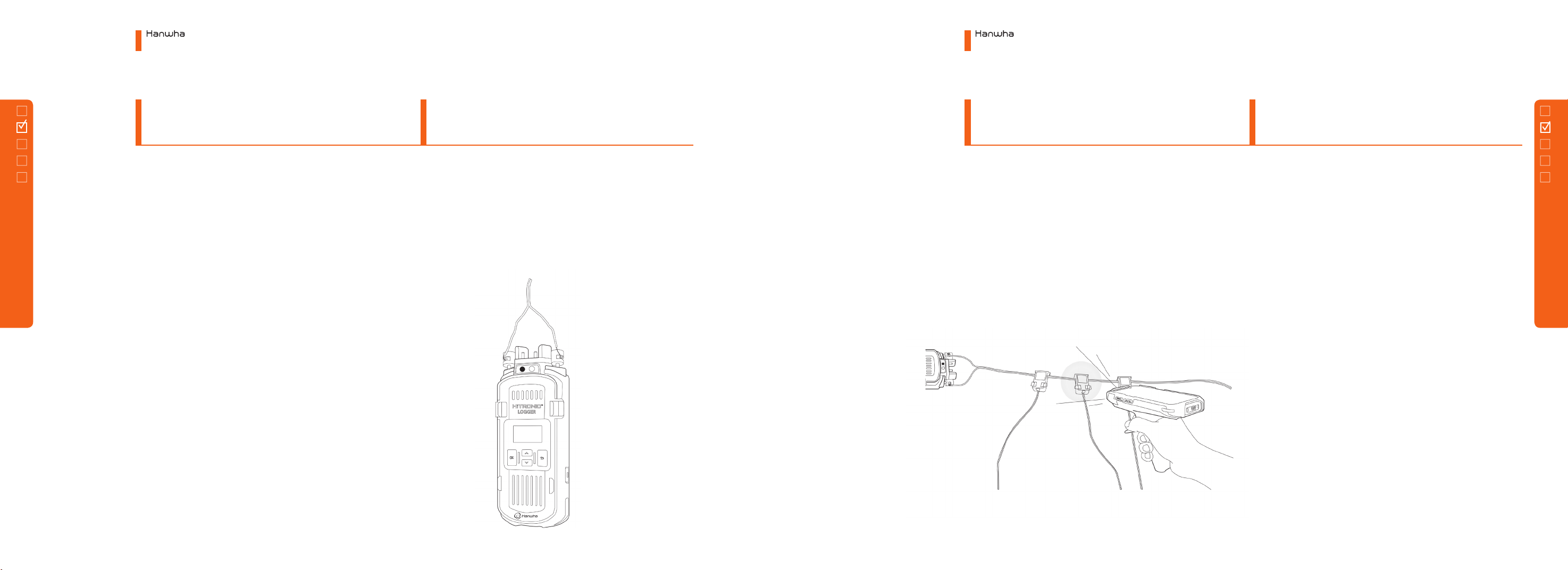
Logger 9
1.3.3
Blaster 10
2. How to Use Devices
2.1 Scanning Type 12
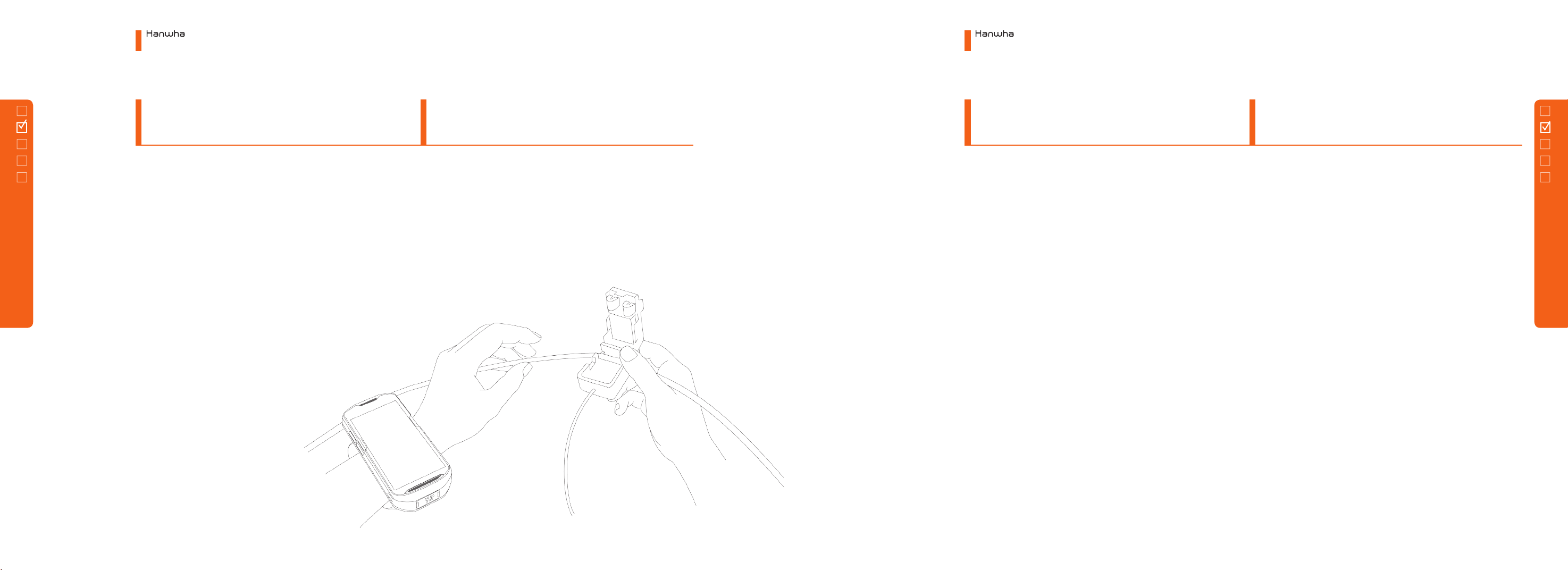
2.2 Logging Type 14
2.3 Tagging Type 16
2.4 Wireless Firing 18
3. Menu Structure
3.1 Planner
3.1.1 Intro 21
3.1.2 Main Screen 21
3.1.3 Main Menu 22
3.1.4 Start Blasting 48
3.1.5 Communication 58
3.1.6 Data transmission 63
3.1.7 Others 65
3.2 Logger
3.2.1 Main Menu 70
3.2.2 DET ID Check 70
3.2.3 Line Test 71
3.2.4 Information 73
3.3 Blaster
3.3.1 Intro 74
3.3.2 Main Screen 74
3.3.3 Setting 75
3.3.4 Configuration Setting 78
3.3.5 Start Blasting 92
4. Maintenance
4.1 Problem Solving
at Planner Work 111
4.2 Problem Solving
at Blaster Work 115
4.3 Problem Solving
for Misfire after Blasting 118
5. Troubleshooting
5.1 HEBS-II Technical Data Sheet 123
5.1 Contacts 129
Contents
1.
Before Use
1. Before Use
1.1 Warnings
1.2 HEBS-II Components
1.3
Each part name and role
7
◦This manual is described based on the settings before on-site provided.
◦If a problem occurs by installing an app that is not provided by Hanwha, it can be difficult to respond immediately.
◦
If a user arbitrarily modifies the system settings or operating system software and experiences functional and
compatibility problems, immediate response may be difficult. Modifying system settings may cause malfunction of
the product or app working.
◦
Any alteration of the software provided by Hanwha or leakage of the software through unofficial channels violates
Hanwha's software license rights.
◦These radio equipments may be radio-interference during operation.
◦
This product has been applied with electronic display of product information. To check the information, run the
Setup app and enter the Information part.
①Blaster
④Harnesswire
⑤HiTRONIC II TM
③Logger
②Planner
Be sure to read this manual
and use the product safely and
correctly before using HEBS-II.
Electronic Blasting System
1. Before Use
Electronic Blasting System
1. Before Use
1.1 Warnings
6
1.2
HEBS-II
Components
1.1
Warnings
1.2 HEBS-II Components
9
Touch Screen
Charging Status LED
Data Capture LED
MIC
Scanning Button
PTT Button
Speaker
Battery
NFC Antenna
Volume Control Button
Scanning Button
Power Button
Exit Window
Interface Connector
Blutooth Status LED
Planner Connector
Charging Port (USB-C type)
Buttons
(Back/Up/Down/OK)
Display
Power Button
Tagging Connector
Power LED
Binding Post
Hand Strap Holder
Electronic Blasting System
1. Before Use
Electronic Blasting System
1. Before Use
8
1.3
Each part
name
and role
1.3.2
Logger
1.3.1
Planner
1.3 Each part name and role
1.3 Each part name and role

Power LED
Power Button
Speaker
Binding Post
Status Indicator LED
Fire Button
Fire Button
Touch Screen Tripod Connector
Belt Strap Holder
Antenna
Charging Port
(USB-C type)
Electronic Blasting System
1. Before Use
10
1.3.3
Blaster
2.
How to Use
Devices
2. How to Use Devices
2.1 Scanning Type
2. 2
Logging Type
2. 3
Tagging Type
2.4
Wireless Firing
1.3 Each part name and role
13
◦Insert a detonator in the end of explosives.
* Insert the detonator to the end of plug (black rubber)
in the explosives.
◦Charge explosives according to the blast design.
◦After completing the charging of explosives, fill it up with
sand to harden.
◦
Set information about delay time after selecting mode at the
Planner (Refer to 3.1.4 Start New Blasting).
◦
Scan QR code of detonator's connector in desired sequence
as in the figure.
◦
Confirm the connection of detonator through
'COMMUNICATION' at the Planner after the scan completion
(Refer to 3.1.5 (3) Communication).
◦As shown in the figure, connect one end of harness wire to
a positive terminal of Logger.
◦Connect Logger on the Planner screen (Refer to 3.1.5 (1)
Logger Information). Running the ‘Line Test’at the planner.
◦Couple a connector of detonator with the harness wire
◦
Connect the harnesswire to a main bus wire and conncect
the wire to the blaster.
◦Turn on the blaster power and check RFID card.
◦
Touch ‘Start Firing’ and check recharging and
communication details.
◦Input password and proceed with ARM.
◦Firing (Refer to 3.3 Blaster).
Electronic Blasting System
2. How to Use Devices
Electronic Blasting System
2. How to Use Devices
12
2.1
Scanning
Type
2.1.3
Scanning
2.1.4
Blasting
2.1.1
Charging
2.1.2
Wiring
2.1 Scanning Type
2.1 Scanning Type
15
◦Equivalent to 1) Charging Explosives of 2.1 Scanning Type. ◦
Select the mode at the Planner to set the information of delay
time (Refer to 3.1.4 Start New Blasting).
◦Couple the detonator connector with the harness wire in
desired sequence.
◦
Check the detonator information through 'COMMUNICATION'
at the Planner after the completion of logging (Refer to 3.1.5 (3)
Communication).
◦
After connecting a detonator to the harness wire and
checking the entering of the next ID, the next detonator must
be connected. (In an open air, although it will not happen,
there is a possibility of an error if they are connected almost at
the same time.
◦Connect one end of harness wire to the positive terminal of
Logger (communicator).
◦Connect the Logger on the Planner screen (Refer to 3.1.5 (1)
Logger Information).
◦Equivalent to 4) Blasting of 2.1 Scanning Type.
Electronic Blasting System
2. How to Use Devices
Electronic Blasting System
2. How to Use Devices
14
2.2
Logging
Type
2.2.3
Logging
2.2.4
Blasting
2.2.1
Charging
2.2.2
Wiring
2.2 Logging Type
2.2 Logging Type

17
◦Equivalent to 1) Charging Explosives of 2.1 Scanning Type. ◦
Select the mode at the Planner to set the information of delay
time (Refer to 3.1.4 Start New Blasting).
◦
Tagging the detonator connector to the terminal of Logger in
desired sequence as shown in the figure.
◦
Check the connection of detonator through
'COMMUNICATION' at the Planner after the completion of
scanning (Refer to 3.1.5 (3) Communication).
◦Equivalent to 2) Wiring of 2.2 Logging Type.
◦Couple the Logger with the Planner as shown in the figure.
◦Equivalent to 4) Blasting of 2.1 Scanning Type.
Electronic Blasting System
2. How to Use Devices
Electronic Blasting System
2. How to Use Devices
16
2.3
Tagging
Type
2.3.3
Tagging
2.3.4
Blasting
2.3.1
Charging
2.3.2
Wiring
2.3 Tagging Type
2.3 Tagging Type
19
◦
Connect all blasters used for wireless blasting through
setting the configuration of blasting (Refer to 3.3.4 Blasting
Configuration Setting).
◦
Connect the harnesswire to a main bus wire and conncect the wire to the
blaster.
◦
Touch 'Start Blasting' on the blaster screen in blaster mode and touch ‘Start
Wireless Blasting'
◦Transmit detonator's data from Planner to Blaster.
◦Maintain the blaster in blaster mode as standby.
◦Proceed with the blasting at Remote (Refer to 3.3.5 Start Blasting).
◦Refer to 2.1 - 2.3 for charging explosives, wiring, scanning,
logging and tagging.
Electronic Blasting System
2. How to Use Devices
Electronic Blasting System
2. How to Use Devices
18
2.4
Wireless
Firing
2.4.3
Proceed with Wireless Blasting
2.4.1
Blast network conguration
2.4.2
Charging and Wiring
2.4 Wireless Firing
2.4 Wireless Firing

21
Available to check
the main menu.
Touch to start a
new blasting.
Electronic Blasting System
3. Menu Configuration
3. Menu Configuration
3.1 Planner
3.2 Logger
3.3 Blaster
3.
3.1
Planner
Menu Configuration
3.1 Planner
3.1.1
Starting Screen
3.1.2
Main Screen
23
◦Group Mode
Available to use for a group blasting when blasting
tunnel and outdoor.
◦Basic Mode Available to use for a small-scale simple pattern blasting.
◦S/W Mode Available to use in a blast design software mode.
◦Logger Available to check Logger connection, line test, detonator
communication and ID check.
◦Blaster Available to transmit data to the blaster.
◦Others Available to check and edit saved information, set
environment, and end.
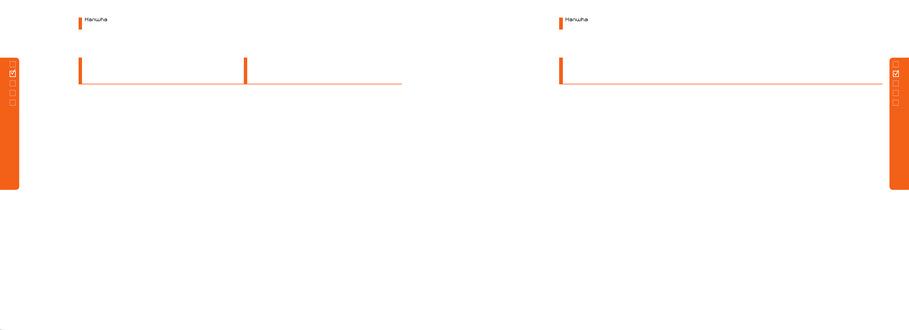
SECTION MOVE
long click ICON ,
and drag to change
the sequence.
◦ADD Touch the button at the
bottom to add a new section.
◦EDIT Click button( Button) on the section
to edit. As shown in the figure, if a section
information window is displayed, edit the
starting time and explanation and click
button.
◦DELETE Click EDIT button on the section item
to delete and click button. If the information
window is displayed, click button.
◦SECTION MOVE To change the sequence of
section, long click ICON ( ), and drag to
change the sequence.
Electronic Blasting System
3. Menu Configuration
Electronic Blasting System
3. Menu Configuration
22
3.1.3
Main Menu
①Section Design
3.1 Planner
3.1 Planner
3.1.3 Main Menu
1) Group Mode - (a) Plan
25
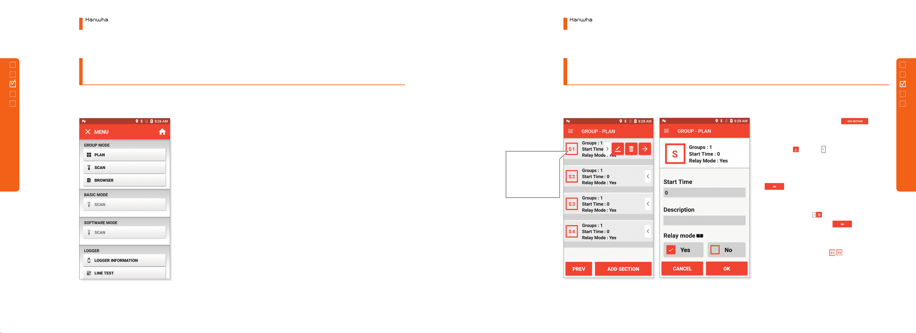
Template - Available
to reflect the preset
information that has
been set in advance.
◦ADD Click button at the bottom to add a group.
◦EDIT Click EDIT ( & Button) button of the group to edit. If a group information window is
displayed, edit group time gap, symbol, and explanation and click button. Click TEMPLATE
at the bottom to reflect the previously set information.
◦DELETE Click button of the group item to delete and click button. If the information is
displayed, click button.
◦GROUP MOVE To change the sequence of group, long click ICON, and drag to change the
sequence.
ADD GROUP
OK
OK
Electronic Blasting System
3. Menu Configuration
Electronic Blasting System
3. Menu Configuration
24
3.1.3 Main Menu
1) Group Mode - (a) Plan
3.1.3 Main Menu
1) Group Mode - (a) Plan
②Group Design
3.1 Planner
3.1 Planner

27
TIME GAP
Available to change the group time
gap.
SYMBOL TEXT
Available to change the symbol
text (Max. 2 alphabets).
EXPLANATION
Available to edit the group
explanation.
SYMBOL COLOR
Available to change the symbol
color.
FONT COLOR
Available to change the font color
of a symbol.
TEMPLATE
There are tunnel, group, user definition
TAPs. Select desired TAP to change at once
to a group information set previously.
Electronic Blasting System
3. Menu Configuration
Electronic Blasting System
3. Menu Configuration
26
3.1.3 Main Menu
1) Group Mode - (a) Plan
3.1.3 Main Menu
1) Group Mode - (a) Plan
3.1 Planner
3.1 Planner

29
Thermal
Movement
Available to
change the
order by clicking
the Icon button
long and
dragging to
move.
◦ADD Click button at the bottom to add a
new row.
◦EDIT Click button of the row to edit. If a row
information window is displayed, edit the name of
the row, the number of decks and the time gap of
holes and click button.
◦DELETE Click button of the row item to delete
and click button. If the information window is
displayed as shown in the figure, click
button.
◦ROW MOVE To change the sequence of rows, long
click and drag it to change the sequence.
◦BINDING There are two types of row. One is
the row for general use, and the other is the
binding row that binds two rows into one. For
the binding row, the delay time is designed
by a type to fire two rows in turn. If using the
binding, it is possible to design to fire left side
and right side in turn at the time of tunnel
blasting.
◦BINDING SETTING For row binding, add two
rows to click icon on right top. The row with
a hole for the first firing, namely, first check a
row which becomes a parent and check a row
which becomes a child. Check two rows and
click icon to change to a binding row.
◦BINDING SEQUENCE CHANGE To change
the roles of parent and child, enter EDIT of the
binding row to click SEQUENCE CHANGE icon.
OK
OK
ADD ROW
Electronic Blasting System
3. Menu Configuration
Electronic Blasting System
3. Menu Configuration
28
3.1.3 Main Menu
1) Group Mode - (a) Plan
3.1.3 Main Menu
1) Group Mode - (a) Plan
3.1 Planner
3.1 Planner
③Row Design

31
Viewing Delayed
Time - Available to
check the delayed
time of corresponding
detonator by clicking
the clock button. Group Add/Delete
Available to add or
delete a group by
dragging to the left
or to the right.
⑤DETONATOR DELETE
Scan QR code of the detonator to delete again.
Hearing beep sound three times to change to
a red color. At this time, click the icon at
the right bottom of a red box to display an
information window and press
button to delete ID.
⑥HOLE ADD
Click a button on right top of scan screen
to add a deck without ID. At this time, decks are
added as many as the number of decks in a row.
⑦Group ADD/DELETE
Click the arrow button at the
bottom of screen to display a window to move
as shown in the figure. At this time, add or delete
a group with button.
①SCAN
Aim to hit the red point on QR code of a detonator. Click
SCAN button to hear beep sound and scan QR code.
②SECTION, GROUP, ROW MOVE
Click icon at the bottom of screen to display
a window to move. Here, click the left or right arrow key
to change SECTION, GROUP, and ROW to move each block.
③ DELAY TIME VIEW
Click button to check the delay time of corresponding
detonator.
④ DETONATOR ID MANUAL INPUT
Click ID input window at the center of
screen to display keyboard. At this time, available to input
detonator ID directly.
OK
Electronic Blasting System
3. Menu Configuration
Electronic Blasting System
3. Menu Configuration
30
3.1 Planner
3.1 Planner
3.1.3 Main Menu
1) Group Mode - (b) Scan
3.1.3 Main Menu
1) Group Mode - (b) Scan
33
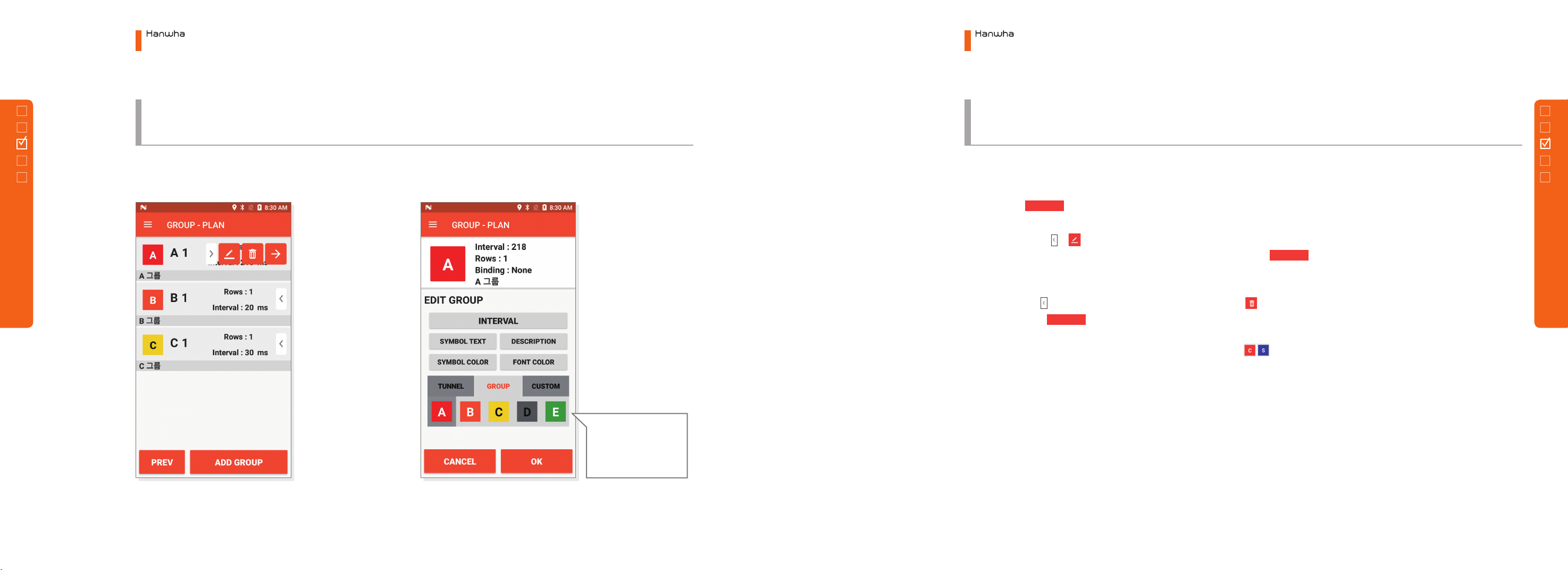
⑧ GROUP ADD ⑨GROUP DELETE
If you drag the Slide
button to the left
on the front page, a
Group Add button
appears as shown in
the figure.
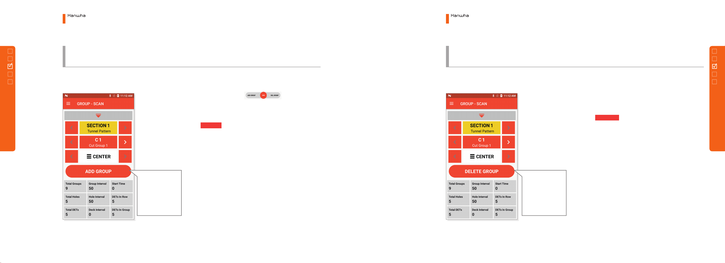
If you drag the Slide
button to the right
on the front page, a
Group Add button
appears as shown in
the figure.
◦Drag the slide button on the
previous page toward the GROUP ADD on the left to
move.
◦button is created. Click this button will
move to the added group with the same new group
information as the current group's information.
◦Other Information Information to refer during
the scanning from the information window at the
bottom.
◦Drag the slide button (Blue Circle from page 19)
toward the GROUP DELETE on the right to move
◦Click to delete the group immediately
if there is no ID in the group or to display DELETE
window if there is at least one ID.
◦At this time, to maintain the group and delete the
hole only, click ‘Delete All Holes of Group’. To delete
the hole of present hole, click ‘Delete All Holes of
Row' button.
◦Other Information Information to refer during
the scanning from the information window at the
bottom.
ADD GROUP
DELETE GROUP
Electronic Blasting System
3. Menu Configuration
Electronic Blasting System
3. Menu Configuration
32
3.1 Planner
3.1 Planner
3.1.3 Main Menu
1) Group Mode - (b) Scan
3.1.3 Main Menu
1) Group Mode - (b) Scan
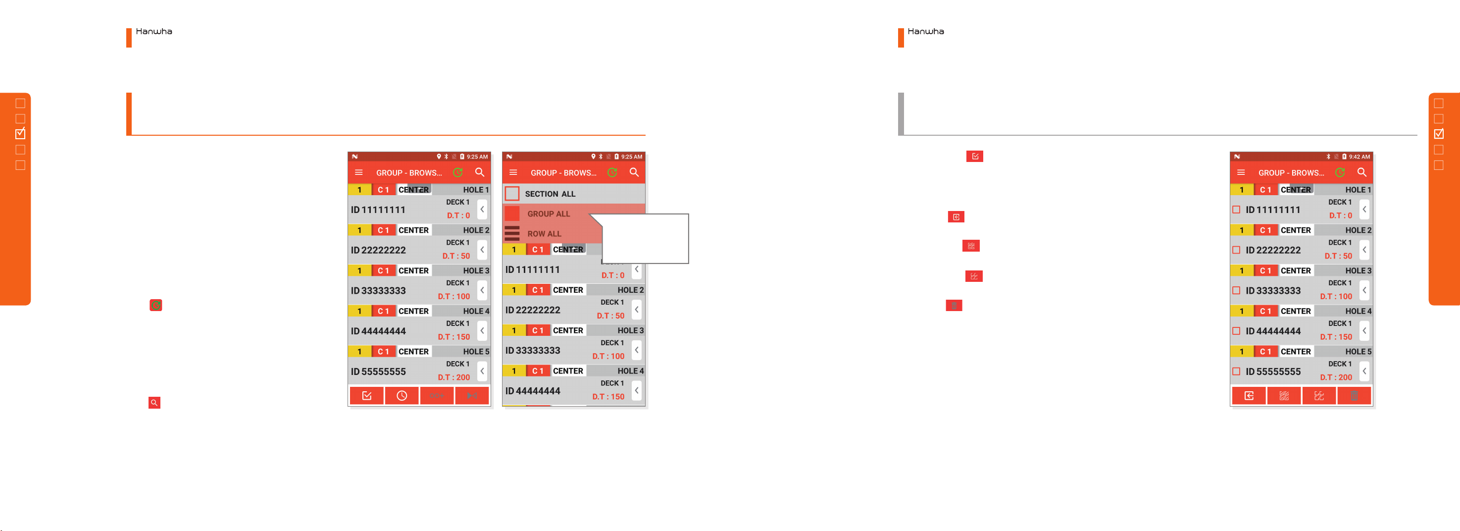
35
ID Search
Search in the list of
selected block only.
①LIST
Browser is the window to edit data looking at the
list of scanned detonator ID.
②BLOCK MOVE
Widget to move section, group and row on top of
the screen. Select each block to display the list of
decks at the bottom of corresponding block.
③DELAY TIME UPDATE
Click button to update the delay time of all
decks.
※Caution
Must edit data and press UPDATE
Please design well to see CAUTION.
④ID SEARCH
Click button on the right top to display a Text
Input window. Input ID to search to display ID on
the list.
※Caution
Search ID only at the list of selected block. To search
every ID, make sure to set entire section, entire group,
and entire row to search.
⑤SELECT Click Select the First button on the left bottom
to display CHECK box for each deck. To select several decks to
delete, work at the selection mode.
◦CANCEL Cancel the selection mode on.
◦ALL SELECT Available to check all decks on the list of.
◦ALL CANCEL Available to cancel all decks on the list of.
◦DELETE Available to delete selected decks on the list of.
Electronic Blasting System
3. Menu Configuration
Electronic Blasting System
3. Menu Configuration
34
3.1 Planner
3.1 Planner
3.1.3 Main Menu
1) Group Mode - (c) Browser
3.1.3 Main Menu
1) Group Mode - (c) Browser
37
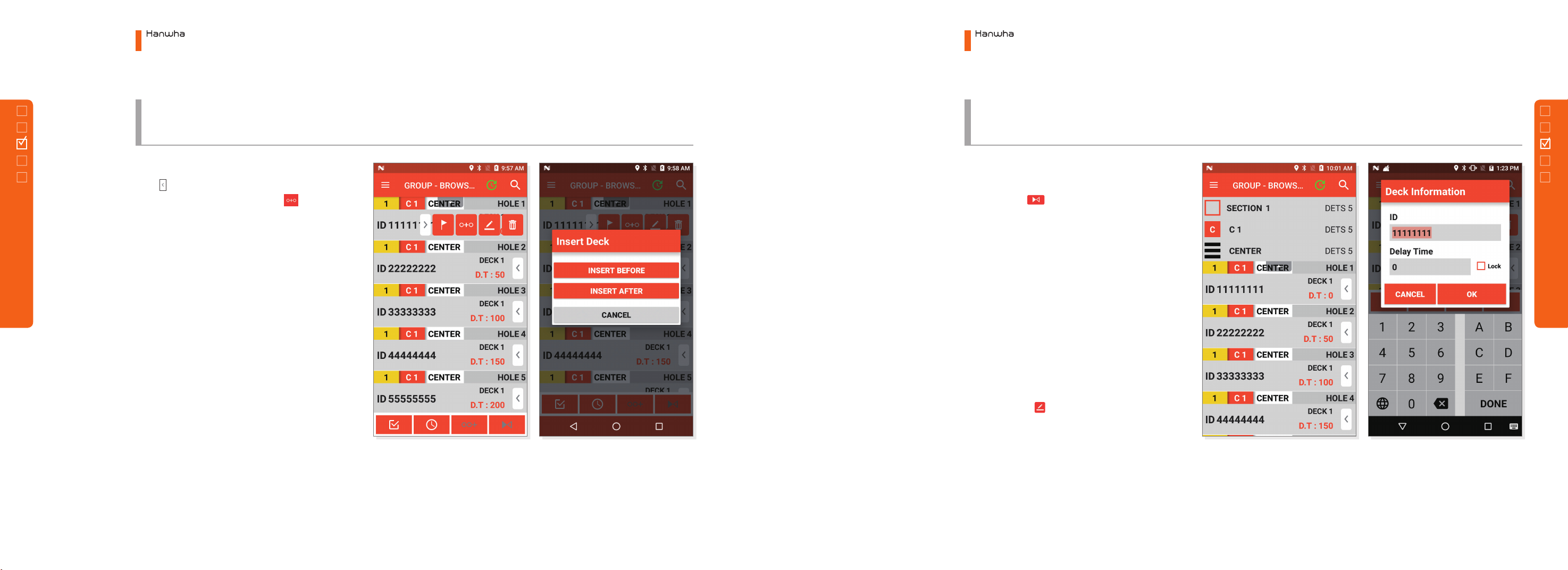
⑥HOLE ADD
Click button of the list item at the location to
add to open the menu, and click button. Add
by judging whether to insert before the selected
item or after.
⑦REVERSAL
Inactivated reversal icon when selecting the entire
block on the ( bottom). Must select a specific
row to activate the reversal. Select REVERSAL to
arrange all decks in the row reversely. Scanning the
sequence of firing reversely by each situation, use
the reversal function to arrange the list reversely.
⑧INSERT
◦Insert by Touch Refer to 6) HOLE ADD.
◦Insert by Scan First, scan ID at the location to
insert. Select the corresponding deck to scan
ID to insert again. On the Deck Insert window,
select whether to insert before or after to insert
at the corresponding location.
⑨EDIT
Click the arrow of the detonator to edit the
deck ID and delay time. At this time, changing the
delay time to become a lock condition.
※Caution
If the delay time becomes a lock condition, it will not
be available to update the delay time even after the
update.
In order to set for the update of delay time again,
you may cancel ‘Lock Check Box’.
Electronic Blasting System
3. Menu Configuration
Electronic Blasting System
3. Menu Configuration
36
3.1 Planner
3.1 Planner
3.1.3 Main Menu
1) Group Mode - (c) Browser
3.1.3 Main Menu
1) Group Mode - (c) Browser
39
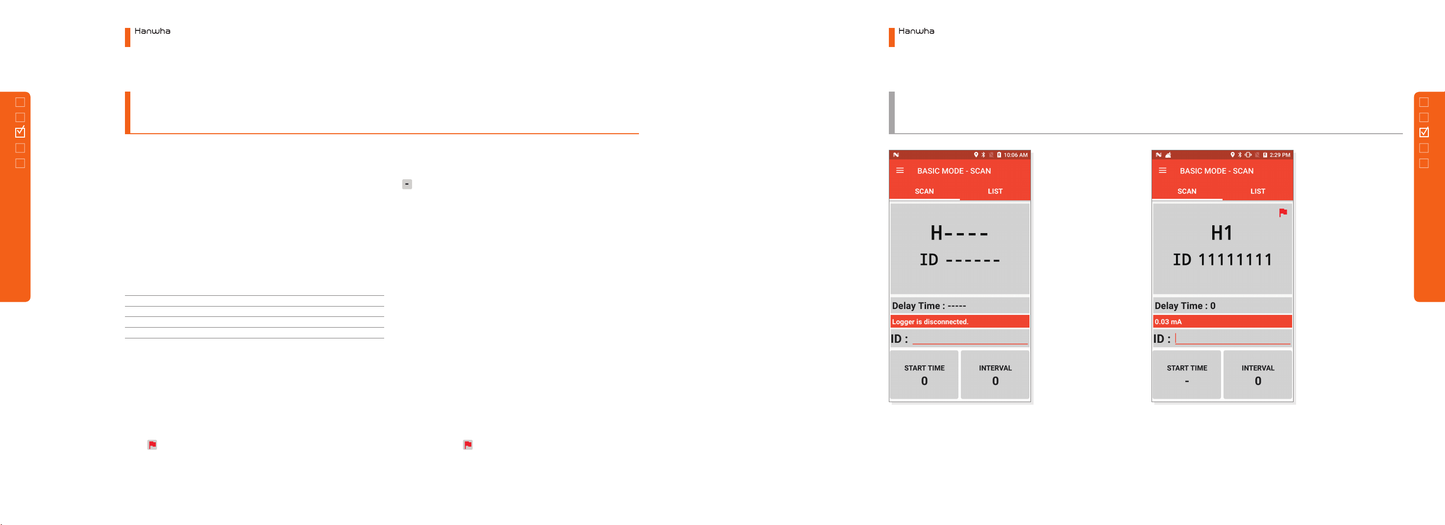
①STARTING TIME
Input the starting time for blasting before scanning. Without input, previously input value
becomes the starting time. The starting time shall be changed with mark after the first ID
scanning. This means to continue time gap without setting the starting time. If the starting time
is changed again in the middle to scan ID, the starting time shall be set again from that step.
②TIME GAP
Click TIME GAP button to display the Time Delay Gap window and change the time gap.
Changing the time gap, a new time gap shall be applied from the scanned detonator.
Ex) 3 shots start from 0 to 50 time gap, and 3 shots from 1000 to record 100 time gap
③DETONATOR ID MANUAL INPUT
Click the ID Input window (grey bar) at the center screen to display keyboard. At this time,
available to input detonator ID directly.
④FLAG SETTING
If it is not sufficient to set the time gap but to scan first, you may mark the location to change
with . If long clicking PTT button on the right side of a device after scanning ID, be
displayed on the scan screen with beep sound. After marking with the flag to finish scanning, it
will be available to set the time gap.
Sequence
Starting Time
Time Gap
Delay Time
1
0
50
0
2
-
50
100
3
-
50
100
4
1000
100
1000
5
-
100
110 0
6
-
100
1200
Electronic Blasting System
3. Menu Configuration
Electronic Blasting System
3. Menu Configuration
38
3.1 Planner
3.1 Planner
3.1.3 Main Menu
2) Basic Mode - (a) Scan
3.1.3 Main Menu
2) Basic Mode - (a) Scan
41
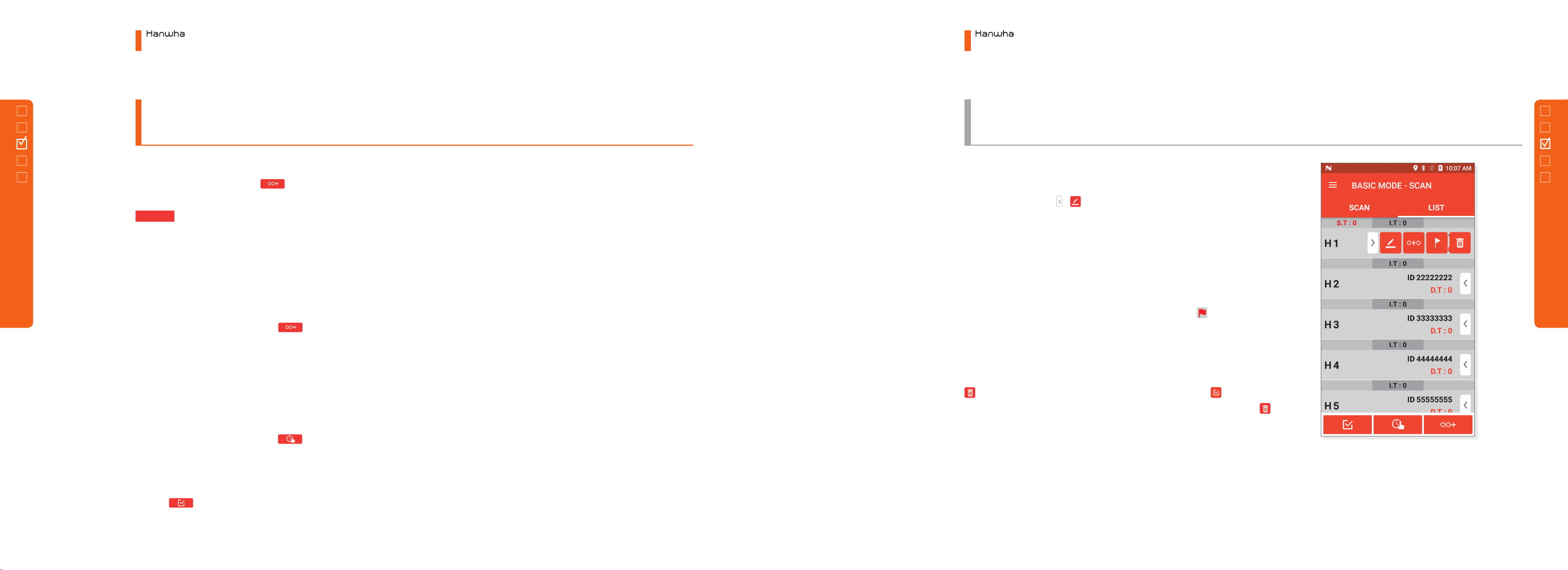
①DETONATOR ADD
To add new detonator, click button at the bottom screen to display
DETONATOR ADD screen. Input ID, starting time and time gap and press
button to add detonator.
②DETONATOR INSERT
◦Insert by Dragging To insert a detonator, proceed with DETONATOR
ADD in number 1) and long click newly added detonator. Then, with
a vibration feedback, available to drag the detonator item to move.
With such method, drag the detonator to the location to insert.
◦Insert by Item Menu Press button of the list item at the location
to add to open the MENU and click [O+O] button. Judge whether to
insert before the selected item or after.
③DELAY TIME EDIT
Difficult to edit one by one in order to comprehensively edit the time
information again in the list. At this time, It is a function to change the
time information simply. Click a button to display Starting Time and
Time Gap buttons. At this time, long click the desired button to display a
window to edit. After editing desired value, click one item by another item
of detonator desired to change for direct reflection. After editing, click the
button for EDIT button to disappear.
④DETONATOR INFORMATION EDIT
To edit one detonator information, click and select the detonator to edit
and press the arrow , button to display the Information window.
Here, edit the information of ID, starting time and time gap and press
OK button to complete the edition of detonator information.
⑤FLAG SETTING
Available to set and cancel the flag set on the scan screen in the list. If
it is not sufficient to set the time gap but to scan first, it is available to
mark with a flag at the location to change. Press the button to set
and cancel the flag.
⑥DELETE
To delete a detonator in the list, select the detonator to delete and click
button. To delete several detonators, click the check button on
the right top screen and check 'Detonator Item' to delete and click
button.
OK
Electronic Blasting System
3. Menu Configuration
Electronic Blasting System
3. Menu Configuration
40
3.1 Planner
3.1 Planner
3.1.3 Main Menu
2) Basic Mode - (b) List
3.1.3 Main Menu
2) Basic Mode - (b) List
Table of contents
Popular Diagnostic Equipment manuals by other brands


NetComm Wireless
NetComm Wireless NDD-0203-02 quick start guide

Pro-tec
Pro-tec PRS 500 C Instructions for use

Foxwell
Foxwell Premier Diagnostic Platform NT909 user manual

Midtronics
Midtronics DCA-8000 instruction manual

Heinzmann
Heinzmann Triton CPM 500 manual

VOLTCRAFT
VOLTCRAFT 10 35 46 operating instructions


