Pro-tec PROGNOST C User manual

PROTEC GmbH & Co. KG
In den Dorfwiesen 14, 71720 Oberstenfeld, Germany
Version: 4.0
Issued: 2021-05-26
Subject to alterations
PROGNOST C
Diagnostic X-ray system mechanics
odel/ID: 7073-9-000X
Basis-UDI-DI: 426050264X013ZJ
Instructions for use
Ident. No. 5073-0-0002

NOTE
All sheets of this document contain proprietary and confidential information of
PROTEC GmbH & Co. KG and is intended for exclusive use by current PROTEC GmbH
& Co. KG customers. Copying, disclosure to other or other use is prohibited without
the express written authorization of PROTEC´s law department. Report any
violations of this requirement to PROTEC GmbH & Co. KG.
© 2021 PROTEC GmbH & Co. KG, Oberstenfeld
These accompanying documents were created and distributed by the documentation department.
Comments and questions about the documentation, please contact:
PROTEC GmbH & Co. KG
In den Dorfwiesen 14 | 71720 Oberstenfeld
Germany
Phone: (+ 49) 7062 – 92 55 0
Fax: (+ 49) 7062 – 92 55 60
E- ail: protec@protec-med.com
Internet: www.protec-med.com

V4.0_2021-05-26 PROGNOST C Instructions for use 5073-0-0002
PROTEC GmbH & Co. KG, In den Dorfwiesen 14, 71720 Oberstenfeld, Germany 3 von 30
Table of contents
Page
Table of contents ........................................................................................................................... 3
Document Effectivity .................................................................................................................... 5
General Notes ................................................................................................................................ 6
echanical – Electric Warning .................................................................................................... 6
To the User ..................................................................................................................................... 6
1
Product description ............................................................................................................ 7
1.1 Introduction ......................................................................................................................................................................................... 7
1.2 Description............................................................................................................................................................................................ 7
1.2.1 Models ......................................................................................................................................................................................... 7
1.2.2 Hardware and Network System Requirements ................................................................................................. 7
1.2.3 Installation ................................................................................................................................................................................ 8
1.2.3.1 Floor capacity ................................................................................................................................................................... 8
1.3 Product specific characteristics ................................................................................................................................................ 8
1.3.1 Radiographic table .............................................................................................................................................................. 8
1.3.2 Floor railed X-ray system tube support .................................................................................................................. 8
1.3.3 Vertical Bucky Wall Stand ................................................................................................................................................
1.4 Intended Use .......................................................................................................................................................................................
1.5 Clinical Benefit ....................................................................................................................................................................................
1.6 Patient Target Group(s) .................................................................................................................................................................
1.7 Medical Conditions to be diagnosed ...................................................................................................................................
1.8 Indications and Contraindications .........................................................................................................................................
1. Intended Operator Group ...........................................................................................................................................................
1.10 Declaration of Conformity ...........................................................................................................................................................
2
Safety Instructions ............................................................................................................ 10
2.1 General safety notice ................................................................................................................................................................... 11
2.1.1 Requirements for operation ....................................................................................................................................... 11
2.1.2 Operating of the radiographic system ................................................................................................................. 11
2.1.3 Operating personnel ....................................................................................................................................................... 11
2.1.4 Pinching and Collision Hazards ................................................................................................................................ 12
2.1.5 Explosion protection ....................................................................................................................................................... 12
2.1.6 Interaction with external devices ............................................................................................................................ 12
2.1.7 Electromagnetic Environment and the influence of devices ................................................................ 12
3
Control elements and device displays ........................................................................... 13
3.1 Control elements and device display of Basic X-ray system ............................................................................... 13
3.1.1 Floor railed X-ray system tube support ............................................................................................................... 13
3.1.2 Radiographic table ........................................................................................................................................................... 14
3.1.3 Vertical Bucky Wall Stand ............................................................................................................................................. 14
4
Handling ............................................................................................................................. 15
4.1 Requirements before and during Operation ................................................................................................................ 15
4.2 Operation of the PROGNOST C ............................................................................................................................................. 15
4.2.1 Releasing the table top brake (positioning the table top) ....................................................................... 15
4.2.2 Positioning the image receptor from the wall stand .................................................................................. 15
4.2.3 Exposures with Mechanics for basic diagnostic X-ray systems ............................................................ 15
4.2.3.1 Position of patients on the table top .............................................................................................................. 15
4.2.3.2 Setting the X-ray unit on the mid moving Bucky, Grid entity ......................................................... 15
4.2.3.3 Inserting a cassette into the cassette tray .................................................................................................... 15
4.2.3.4 Adjusting the focus-film distance (SID) ......................................................................................................... 16
4.2.3.5 Adjusting the light resp. X-ray field .................................................................................................................. 16
4.2.3.6 Exposure preparation / exposure release .................................................................................................... 16
4.2.3.7 Overtable exposures ................................................................................................................................................. 16
4.2.4 Operation at vertical wall stand................................................................................................................................ 16

V4.0_2021-05-26 PROGNOST C Instructions for use 5073-0-0002
PROTEC GmbH & Co. KG, In den Dorfwiesen 14, 71720 Oberstenfeld, Germany 4 von 30
4.2.4.1 Adjustment of the X-ray unit to the mid of a cassette or Bucky/Grid entity of aX-ray
system image receptor stand (vertical center beam) ................................................................................................. 16
4.2.4.2 Adjustment of the source to image-receptor distance (SID) ........................................................... 16
4.2.4.3 Adjustment of the light-/ radiation field....................................................................................................... 16
4.2.4.4 Exposure preparation/ release ............................................................................................................................ 17
4.3 Function of the PROGNOST C ................................................................................................................................................ 17
4.3.1 Switching On/Off the PROGNOST C ...................................................................................................................... 17
5
Safety and aintenance ................................................................................................... 18
5.1 Introduction ...................................................................................................................................................................................... 18
5.2 Reusability .......................................................................................................................................................................................... 18
5.3 Cleaning and Disinfection ........................................................................................................................................................ 18
5.3.1 Cleaning .................................................................................................................................................................................. 18
5.3.2 Disinfection ........................................................................................................................................................................... 18
5.4 Inspection and maintenance ................................................................................................................................................. 1
5.4.1 Daily monitoring before and during investigation Operation .............................................................. 1
5.4.2 Regular Monitoring .......................................................................................................................................................... 1
5.4.2.1 Quality control by the user.................................................................................................................................... 1
5.4.3 Maintenance ........................................................................................................................................................................ 1
5.4.4 Warranty .................................................................................................................................................................................. 20
5.4.5 Product Service Life ......................................................................................................................................................... 20
5.4.6 Further Information ......................................................................................................................................................... 20
5.4.7 Applied Parts and parts which get handled like an application part ................................................ 20
5.4.8 Disposal ................................................................................................................................................................................... 20
6
Electrical data ..................................................................................................................... 21
6.1 Connection ........................................................................................................................................................................................ 21
6.2 Electromagnetic Compatibility (EMC) after EN 60601-1-2 ................................................................................... 21
6.2.1 Guidelines and Manufacturers declaration – electromagnetic interference (non-life
supporting device) ................................................................................................................................................................................... 21
7
Technical Data .................................................................................................................... 24
7.1 Dimensions ........................................................................................................................................................................................ 24
7.2 X-ray system table ......................................................................................................................................................................... 25
7.2.1 X-ray mattress ...................................................................................................................................................................... 25
7.3 Bucky unit ........................................................................................................................................................................................... 25
7.4 X-ray system tube support, floor stand ............................................................................................................................ 25
7.5 Vertical X-ray system image receptor stand .................................................................................................................. 25
7.6 Attenuation Equivalent .............................................................................................................................................................. 26
7.6.1 Protection Art and Protection Class ....................................................................................................................... 26
7.7 Environmental ................................................................................................................................................................................. 26
7.7.1 Environmental conditions during operation ................................................................................................... 26
7.7.2 Environmental Conditions for Shipping and Storage ................................................................................ 26
8
Description of symbols, labels and abbreviations ....................................................... 27
8.1 Symbols ............................................................................................................................................................................................... 27
8.2 Type label ........................................................................................................................................................................................... 28
8.3 Labels .................................................................................................................................................................................................... 28
8.4 Position symbols and labels .................................................................................................................................................... 2
8.5 Abbreviations ................................................................................................................................................................................... 30

V4.0_2021-05-26 PROGNOST C Instructions for use 5073-0-0002
PROTEC GmbH & Co. KG, In den Dorfwiesen 14, 71720 Oberstenfeld, Germany 5 von 30
NOTE
The information contained in this document conforms to the configuration of the
equipment as of the date of manufacture. Revisions to the equipment subsequent
to the date of manufacture will be addressed in service updates distributed to the
PROTEC Technical Service Organization.
Document Effectivity
Revision
No. Date List of effective
pages Comments Author
1.0 2020-11-26 all Original issue
2.0 2021-02-25 Front Page, 7, 11,
14, 15, 18, 23, 27
Product picture, Warning mattress,
Compatible components, mattress
at characteristic table added,
symbols and labels, cleaning,
mattress added to technical data
table
3.0 2021-03-11
7, 8, 18, 1 , 20,
21, 23, 24, 25, 26,
27
X-ray mattress description,
compatible components, note X-ray
mattress at characteristic table,
cleaning, disinfection, lifetime,
applied parts, symbols and labels,
chapter power supply connection,
X-ray mattress changed at technical
data table, note attenuation
equivalent
4.0 2021-05-26 all V3.0 transferred to new layout
(MDR)
MB

V4.0_2021-05-26 PROGNOST C Instructions for use 5073-0-0002
PROTEC GmbH & Co. KG, In den Dorfwiesen 14, 71720 Oberstenfeld, Germany 6 von 30
General Notes
WARNING!
In order to maintain the set and tested requirements of the 60601 series of
standards, the E system must not be modified during its actual operating
life.
echanical – Electric Warning
WARNING!
All of the movable assemblies and parts of this equipment should be operated
with care and routinely inspected in accordance with the manufacturer's
recommendations contained in the equipment accompanying documents.
aintenance and service is only to be performed by customers authorized by
PROTEC GmbH & Co. KG.
Live electrical terminals are deadly.
Do not remove flexible high-tension cables from X-ray tube cover or high-
tension generator and/or access covers from X-ray generator.
For all components of the equipment protective earthing means must be
provided in compliance with the national regulations.
Failure to comply with the foregoing may result in serious or fatal bodily
injuries to the operator or those in the area..
To the User
NOTE
The user of these accompanying documents is required to carefully read through
and carefully consider the instructions, warnings and cautions contained therein
before starting operation.
Even if you have already operated similar systems, changes in the design,
production and functional routine of the system described here may have been
made, which have a significant influence on the operation.
Assembly and service works on the system described here must be carried out by
authorised and qualified personnel from PROTEC GmbH & Co. KG. Assembly
personnel and other persons who are not employees of the technical service
department of PROTEC GmbH & Co. KG are requested to contact the local branch of
PROTEC GmbH & Co. KG before assembly or service work is started.
For assembly and service works, it is necessary to use the "Technical Description” of
the product and to observe the points it contains.
NOTE
The usage of the product in combination with accessories not authorized by
PROTEC is forbidden.
NOTE
According to Regulation (EU) 2017/745 of medical devices, all serious incidents
related to the device must be reported to the manufacturer and the responsible
authority of the Member State where the user and/or the patient is established.

V4.0_2021-05-26 PROGNOST C Instructions for use 5073-0-0002
PROTEC GmbH & Co. KG, In den Dorfwiesen 14, 71720 Oberstenfeld, Germany 7 von 30
1
Product description
1.1 Introduction
This user manual describes the special features and operational aspects of the PROGNOST C,
knowledge of which are required for efficient and effective use of the radiographic system.
Prior to working with the X-ray systems mechanics PROGNOST C, it is required that the user read the
safety notes as well as the chapter regarding operation.
1.2 Description
The mechanics for basic diagnostic X-ray systems PROGNOST C is constituted of a fixed elevating
patient positioning table with floating table top (incl. X-ray mattress), a completely integrated tube
column stand, a fixed double operating mode wall stand and an electronic cabinet (without X-Ray
components).
The floating table top can be locked in a longitudinal and transverse direction using an
electromagnetic brake. The brake is controlled by a light barrier.
The table is prepared for the installation of a longitudinally sliding Bucky or Grid entity, an anti-scatter
grid and a measuring chamber intended for use with an automatic exposure control.
The mechanics for basic diagnostic X-ray systems PROGNOST C integrates a on the radiographic table
fixed biocompatible x-ray mattress. This mattress is specially designed for X-ray imaging diagnostics.
The X-ray mattress can be removed for cleaning.
The tube column stand is guided by one rail, which is fixed on the ground behind the table. All
movements of the column stand are well guided and therefor smooth. The movements of the column
stand (horizontal and rotational) and desired positions are fixed using an electromagnetic braking
system. The carrying arm is prepared for the installation of an X-Ray tube assembly (X-Ray tube,
collimator and control panel with integrated controls).
1.2.1 odels
PROGNOST C 7073- -0001 Wall stand left
PROGNOST C 7073- -0002 Wall stand right
Optional Accessories
The PROGNOST C can be equipped or customized with the following accessories:
•Patient extending handle
Compatible components (stand-alone products) and possible combinations
The below mentioned components/products are not included with the standard delivery of
PROGNOST C but nevertheless can be combined with the PROGNOST C.
•Collimator
•X-ray tube assembly
•X-ray generator
•Measuring Chamber
•Dose area product meter system
•Anti-scatter grid
•Different direct X-ray-systems (RAPIXX-series)
(consisting of DR-detector, Interface Box, and Software)
1.2.2 Hardware and Network System Requirements
As a stand-alone product, the PROGNOST C has no hardware or network connection and therefore no
hardware or network requirements.

V4.0_2021-05-26 PROGNOST C Instructions for use 5073-0-0002
PROTEC GmbH & Co. KG, In den Dorfwiesen 14, 71720 Oberstenfeld, Germany 8 von 30
1.2.3 Installation
See separate “Installation manual” PROGNOST C.
Contact information of persons which are qualified to make installations are requestable at:
PROTEC GmbH & Co. KG
In den Dorfwiesen 14 | 71720 Oberstenfeld
Germany
Telephone: +4 (0) 7062 – 2 55 0
Fax: +4 (0) 7062 – 2 55 60
E-Mail: protec@protec-med.com
Internet: www.protec-med.com
1.2.3.1 Floor capacity
NOTE
The X-ray system is primarily made of metal pieces. This has a main role in the
weight of the device.
The X-ray system PROGNOST C has a weight of 545kg.
Every technician is obliged to check the ground load. Also double bottoms and
hollow floors have to be taken into account.
1.3 Product specific characteristics
1.3.1 Radiographic table
•Floating table top
•Table top colour – white
•Electromagnetic table top brake for effortless patient positioning
•A low (optimized) distance between the table top surface and the film (detector) surface
•Large adjustment range of the table top for position of the patient
•Reliable construction
•Prepared for the installation of a Bucky with anti-scatter grid and 3-field measuring chamber
intended for the use with automatic exposure control
•Useable for variable cassette/detector sizes. Formats from 13 cm x 18 cm (5” x 7”) to 43 cm x 43
cm (17” x 17”), depending on analogue or digital use.
•X-ray mattress (attached on the radiographic table, biocompatible, 21 0 mm x 800 mm x 15
mm, provides a convenient and comfortable patient positioning on the X-ray table)
1.3.2 Floor railed X-ray system tube support
•Ceiling-free column stand intended for use within rooms with a ceiling height of at least 2.20
meters
•Wide range of application
•Small wall distance allows good space utilization
•Control elements within the command arm well placed and easy to activate
•Reproducible positioning of the X-ray tube assembly (positions resulting from rotation around
the axis of the carrying arm) through angle indicator
•Vertical range of travel of the focus height from 40.0 cm up to 176.5 cm during horizontal
beam projection
•Electromagnetic brakes for the longitudinal movement of the column stand, the vertical
movements of the carrying arm, the rotational movements of the X-ray tube assembly around
the axis of the carrying arm +/-135°.
•Integrated safety connector for automatically centring the X-ray tube assembly and the Bucky
in the longitudinal direction.

V4.0_2021-05-26 PROGNOST C Instructions for use 5073-0-0002
PROTEC GmbH & Co. KG, In den Dorfwiesen 14, 71720 Oberstenfeld, Germany von 30
1.3.3 Vertical Bucky Wall Stand
•Space saving with minimal footprint
•Wall – floor mounting of floor mounting
•cassette loading from the right or left side (specified at installation)
•Useable for variable cassette/detector sizes. Formats from 13 cm x 18 cm (5” x 7”) to 43 cm x 43
cm (17” x 17”), depending on analogue or digital use.
1.4 Intended Use
The X-ray system mechanics PROGNOST C is designated as a component to be used for the assembly
of a diagnostic X-ray system for various routine applications in planar X-ray imaging in human
medicine.
1.5 Clinical Benefit
Considered in isolation, no clinical benefit can be shown for X-ray system mechanics.
As components of diagnostic X-ray systems in human medicine, they contribute to the clinical benefit
of X-ray systems, which consists of the generation of conventional two-dimensional X-ray images for
creation or specification of findings as a basis for treatment decisions.
1.6 Patient Target Group(s)
The intended patient group includes all people for whom a justifying indication for a medical X-ray has
been given by a physician with the necessary expertise in radiation protection.
There are no general or fundamental restrictions on the patient group regarding age, gender, origin
and patient condition.
1.7 edical Conditions to be diagnosed
As standalone products, X-ray system mechanics have no intended main effect in or at the human
body. Therefore, considered in isolation, no indications and contraindications can be shown for them.
1.8 Indications and Contraindications
As standalone products, X-ray system mechanics have no intended main effect in or at the human
body. Therefore, considered in isolation, no indications and contraindications can be shown for them.
1.9 Intended Operator Group
As a component of a diagnostic X-ray system, PROGNOST C is intended exclusively for use by
professional users who are trained in the operation of diagnostic X-ray systems in accordance with the
respective national regulations and who are familiar with the proper handling, use and operation and
also have been instructed in the permitted conjunction with other medical products, objects and
accessories.
Appropriate users can be, for example: X-ray technicians, X-ray assistants, medical technical X-ray
assistants, surgeons, casualty surgeons, orthopaedists and other trained medical personnel.
1.10 Declaration of Conformity
This product complies with the requirements of Regulation (EU) 2017/745 of the European
Parliament and of the Council of 5 April 2017 concerning medical devices, including all
applicable corrigenda.
The declaration of conformity is available upon request from PROTEC:
PROTEC GmbH & Co. KG
In den Dorfwiesen 14 | 71720 Oberstenfeld
Germany
Phone: (+ 4 ) 7062 – 2 55 0
Fax: (+ 4 ) 7062 – 2 55 60
E-Mail: protec@protec-med.com
Internet: www.protec-med.com

V4.0_2021-05-26 PROGNOST C Instructions for use 5073-0-0002
PROTEC GmbH & Co. KG, In den Dorfwiesen 14, 71720 Oberstenfeld, Germany 10 von 30
2
Safety Instructions
NOTE
Contains information that are relevant to the usage.
xxx
CAUTION!
Contains information that can cause damage to properties at
non conformity.
xxx
WARNING!
Contains information that can cause personal injuries at
nonconformity.
xxx
WARNING!
Warning of radioactive substances or ionisating rays. Contains
information that can cause personal injuries at non conformity.
xxx
Adjustments and calibrations that are described within the user manual must be made, with the aid of
The technical description for the system, by the PROTEC GmbH & Co. KG customer service
department or a PROTEC GmbH & Co. KG authorized service technician.
NOTE
Every delivered manual has to be read and the safety notes have to be observed.
NOTE
After installation the commissioning have to be recorded with the PROTEC
acceptance protocol.
CAUTION!
The instructions for use contain all the information relevant to safety in order
to generally put the PROGNOST C into operation. The device may only be
operated by appropriately trained and trained personnel. In this context,
operation is ensured by clear symbols on the control elements. All further
information and instructions can be found on the supplied data carrier (USB,
CD or DVD). This information applies in its entirety as an appendix to these
instructions for use and must be observed.
NOTE
Every operating elements are described in the corresponding manual.

V4.0_2021-05-26 PROGNOST C Instructions for use 5073-0-0002
PROTEC GmbH & Co. KG, In den Dorfwiesen 14, 71720 Oberstenfeld, Germany 11 von 30
2.1 General safety notice
2.1.1 Requirements for operation
WARNING!
Protection Class I E device
To reduce the risk of electric shock, this unit is designated exclusively for
connection to a supply network with protective earth.
The power for the components of radiographic system PROGNOST C is
designated to be exclusively supplied through a direct connection to the
available X-Ray generator.
The PROGNOST C is a E Class I product (according to EN 60601-1). To reduce
the risk of electric shock, this unit is designated exclusively for connection to a
supply network with protective earth.
WARNING!
The positioning and support of a patient on the X-ray system table must not
be carried out without an X-ray mattress!
2.1.2 Operating of the radiographic system
When having troubles with operating of the PROGNOST C, immediately call the Service of PROTEC or
an authorized service and stop the using of the PROGNOST C.
2.1.3 Operating personnel
The PROGNOST C should only be operated by personnel who are trained in accordance with the
corresponding national regulations in the use and operation of diagnostic X-Ray systems.
NOTE
Only properly trained and authorized personnel are allowed to word with the
PROGNOST C.
The user, as well as the service personnel, must pay attention to the warnings, notices and safety
instructions located on the device and in the user manual. Failure to comply with the information
provided can lead to injury.
NOTE
Operating personnel are required to acquaint themselves with all warnings
(warning signs) located on the device. They serve to ensure the safety of the
operator as well as others and set a basic for orderly operation.

V4.0_2021-05-26 PROGNOST C Instructions for use 5073-0-0002
PROTEC GmbH & Co. KG, In den Dorfwiesen 14, 71720 Oberstenfeld, Germany 12 von 30
2.1.4 Pinching and Collision Hazards
CAUTION!
Ensure that while using any product that can be lowered, raised or moved in
different directions, neither yourself (operator), the patient or any third party
finds themselves in a hazardous position (area of movement). Remove all
objects (e.g. chairs, pushcarts) from known collision areas.
Be aware that careless or improper adjustment of the radiographic system
(movement of column, detector Bucky, Vertical Bucky wall stand and table
top) can lead to damage of the X-Ray components, unusable X-Ray images
and injury to the patient. Failure to pay attention can lead to damage of the
radiographic system as well as external objects.
2.1.5 Explosion protection
These PROGNOST C is not designated for use within areas with explosive hazards.
2.1.6 Interaction with external devices
Unwanted interaction with external devices is not known.
2.1.7 Electromagnetic Environment and the influence of devices
CAUTION!
The use of other accessories, other converters and other cables than those
specified by PROTEC or provided in the documentation of the component
manufacturer can result in increased electromagnetic interference or reduced
electromagnetic immunity of the device and lead to defective operation.
CAUTION!
The use of the PROGNOST C immediately next to other devices or with other
devices in a stacked form should be avoided, as this could result in defective
operation. If use in the manner described above is nevertheless necessary, the
PROGNOST C and the other devices should be observed to ensure that they
are working properly.
NOTE
The properties of this device, determined by emissions, allow its use in industrial
areas and in hospitals (CISPR 11, class A). When used in residential areas (for which
class B is usually required by CISPR 11), this device may not provide adequate
protection for radio services. The user may need to take remedial measures such as
relocating or realigning the device.
The PROGNOST C is intended for use in an environment in professional health care facilities (e.g., clinics,
surgery centres, physiology practices ...)

V4.0_2021-05-26 PROGNOST C Instructions for use 5073-0-0002
PROTEC GmbH & Co. KG, In den Dorfwiesen 14, 71720 Oberstenfeld, Germany 13 von 30
3
Control elements and device displays
3.1 Control elements and device display of Basic X-ray system
3.1.1 Floor railed X-ray system tube support
Rail Slide
When operator wants to move the tube stand at desired position horizontally, it can
be moved manually while holding this button.
UP/DOWN
When operator wants to move the tube arm vertically at desired position, it can be
moved manually while holding this button.
Tube Rotation
When operator wants to rotate the tube, it can be rotated manually while holding this
button.
All Free Zone
It will allow to move the tube horizontally on the rail and up/down except the tube
rotation.
Tube Rotation
Rail Slide
All Free Tube UP/DOWN

V4.0_2021-05-26 PROGNOST C Instructions for use 5073-0-0002
PROTEC GmbH & Co. KG, In den Dorfwiesen 14, 71720 Oberstenfeld, Germany 14 von 30
3.1.2 Radiographic table
WARNING!
The positioning and support of a patient on the X-ray system table must not
be carried out without an X-ray mattress!
The red line in the figure is the "ALL-FREE" switch. By bringing a foot or any object in this
area, the "ALL-FREE" switch will be activated. With the switch checked, it is available to move
the table top in any direction.
3.1.3 Vertical Bucky Wall Stand
UP/DOWN lock
Release button
For vertical movement of Bucky, it is available to move either up or down the Bucky manually
while holding the UP/DOWN button as the figure
Detailed information please find in the enclosed User Manual of the PROGNOST C.
All Free Switch,
light barrier
Power ON/OFF

V4.0_2021-05-26 PROGNOST C Instructions for use 5073-0-0002
PROTEC GmbH & Co. KG, In den Dorfwiesen 14, 71720 Oberstenfeld, Germany 15 von 30
4
Handling
4.1 Requirements before and during Operation
It must be ensured that the surfaces in contact with patients are disinfected before the X-ray
examination of each patient (see chapter 5.3).
4.2 Operation of the PROGNOST C
4.2.1 Releasing the table top brake (positioning the table top)
By actuating the light barrier with the foot, the brakes of the table top are released, whereby the table
top can be moved floating by hand.
CAUTION!
The corner of the table top are relatively sharp.
When moving the table top horizontally as well as when getting on and off
the patient, the corners of the table top must be observed.
Prior to patient positioning, the X-ray unit must be brought into the required exposure
position.
4.2.2 Positioning the image receptor from the wall stand
By pressing the release button on the wall stand, the brakes for the Grid device are released, the Grid
device can be moved by hand.
4.2.3 Exposures with echanics for basic diagnostic X-ray systems
4.2.3.1 Position of patients on the table top
WARNING!
The positioning and support of a patient on the X-ray system table must not
be carried out without an X-ray mattress!
•Move the table to a position in which the patient can climb onto the table surface as easily as
possible.
•Center the table top as much as possible (back/front).
•The patient should take place in the middle of the table top and also leave at this position.
4.2.3.2 Setting the X-ray unit on the mid moving Bucky, Grid entity
•Press the button “Rail Slide” off the brake for the longitudinal motion of the tube stand.
•The handles on both sides of the control arm include.
•Moving the X-ray unit in the longitudinal direction of the Bucky table so unit the moving grid snaps
into the safety coupling.
4.2.3.3 Inserting a cassette into the cassette tray
•A film cassette may be placed into the cassette tray, when the X-ray tube assembly is positioned.
•Pull out the cassette tray by its handle from the Bucky unit until it hits the forward stop.
•The cassette clamps center the cassette transversely within the cassette tray. Rotate its latch
counter clockwise to unlock it.
•Open the cassette clamps far enough to insert a cassette of the desired size.
•At table Bucky insert the cassette, with its transverse centerline aligned with the notch in the
cassette clamps or by engaging the cassette positioner in the size of the cassette corresponding
detent (13 cm, 18 cm, 24 cm, 30 cm, 35 cm, 40 cm or 43 cm), push the cartridge to the cassette
positioner.

V4.0_2021-05-26 PROGNOST C Instructions for use 5073-0-0002
PROTEC GmbH & Co. KG, In den Dorfwiesen 14, 71720 Oberstenfeld, Germany 16 von 30
•Push the cassette clamps against the cassette, and rotate the latch into the locked position.
•Push the cassette tray fully into the Bucky unit.
4.2.3.4 Adjusting the focus-film distance (SID)
•Set the X-ray unit with a tape measure at the collimator or the display on the tube to the desired
focus-film distance (SID).
•Press the button “Tube UP/DOWN” off the brake to adjust the height of the X-ray unit.
4.2.3.5 Adjusting the light resp. X-ray field
•Press the collimator light switch (button 3, figure collimator) to turn on the collimator light, and
view the opening of the collimator shutter in both axes relative to the cassette size scales.
•Several FFD scale (adjuster 1 and 2, figure collimator) are provided to indicate the correct settings
of the collimator adjustment controls for the collimator shutters for several cassette sizes so that
the light beam and the X-ray filed can be limited to the desired cassette size in both axes. Adjust
cassette size as required using the collimator adjustment controls. Reduce shutter openings to
objects size for better image quality.
4.2.3.6 Exposure preparation / exposure release
•At the X-ray generator operator console control panel, select the desire X-ray equipment (Bucky
table with Bucky unit) by selecting the corresponding X-ray equipment/exposure technique switch.
•Press the desired Anatomically Programmed Radiography (APR) switch or manually select the
desired exposure factors. Start the exposure by pressing the switches for exposure
preparation/exposure release.
4.2.3.7 Overtable exposures
•Place a cassette to the desired position on the table top.
•Move X-ray tube to the desired position and adjust SID.
•Press the collimator light switch (button 3, figure collimator) to turn on the collimator light, and
view the opening of the collimator shutters in both axes relatives to the cassette and object size.
•Place object on cassette.
•Adjust the light field with the adjuster 1 and 2 (figure Collimator) onto the size of the used cassette.
So the radiation field will be limited to the size of the cassette.
•At the X-ray generator operator console control panel, select the desired X-ray equipment (Bucky
table without Bucky unit) by selecting the corresponding X-ray equipment/exposure technique
switch.
•Press the desired Anatomically Programmed Radiography (APR) witch or manually select the
desired exposure factors. Start the exposure by pressing the switches for exposure preparation and
exposure release.
4.2.4 Operation at vertical wall stand
4.2.4.1 Adjustment of the X-ray unit to the mid of a cassette or Bucky/Grid entity of aX-ray
system image receptor stand (vertical center beam)
•By pressing button “Tube Rotation” the brake for the rotation of the Collimator will be released.
•Swing the X-ray unit to the X-ray system image receptor stand.
•Set the Bucky, Grid entity on the vertical stand to the size of the patient, see figure vertical Bucky
Wall Stand.
4.2.4.2 Adjustment of the source to image-receptor distance (SID)
•Release the longitudinal movement brake of the column by pressing button “Rail Slide” and adjust
the source to image-receptor distance (SID) which will be used for the exposure. Notice the focus
area of the scanning unit, Bucky and Grid entity. Those settings have to be done with the
measuring tape inside the collimator or with the markings on the upper guidance of the column.
4.2.4.3 Adjustment of the light-/ radiation field
•By using the button “Tube UP/DOWN” the button of the brake for adjusting the height will be
released.

V4.0_2021-05-26 PROGNOST C Instructions for use 5073-0-0002
PROTEC GmbH & Co. KG, In den Dorfwiesen 14, 71720 Oberstenfeld, Germany 17 von 30
•Set the collimator to the requested height and align it to the Bucky by using the light-beam
localizer “Tube UP/DOWN”.
•Release Button “Tube UP/DOWN” to activate the height-adjustable brake for the collimator.
•By using button 3 (figure Collimator) the light-beam will be activated to control the vent of the
collimator to the used cassette.
•With the adjuster 1 and 7 (figure Collimator) set the lamellas of the Collimator to the size of the
used cassette. The settings will be done on the scale 6 and 7 (figure Collimator) to the according
cassette source to image-receptor distance (SID). So the light-/ radiation field is limited to the
according cassette.
4.2.4.4 Exposure preparation/ release
•Select the used device on the console of the generator (vertical-grid recording device).
•Select the requested organ program or the requested exposure details, and start the exposure by
using the control element for exposure preparation/ release.
4.3 Function of the PROGNOST C
4.3.1 Switching On/Off the PROGNOST C
NOTE
The Mechanics for basic diagnostic X-ray systems must be switched on!
The PROGNOST C starts automatically when the system is switched on and is not started separately.
The PROGNOST C switches off automatically when the system is switched off and is not switched off
separately.

V4.0_2021-05-26 PROGNOST C Instructions for use 5073-0-0002
PROTEC GmbH & Co. KG, In den Dorfwiesen 14, 71720 Oberstenfeld, Germany 18 von 30
5
Safety and aintenance
WARNING!
Caution, risk of electric shock!
Turn off the PROGNOST C before cleaning or disinfecting. This disconnects the
PROGNOST C from the power source and avoids the risk of electric shock.
5.1 Introduction
In this chapter you will find information about safety and maintenance that are necessary to ensure the
correct and reliable function of the device after installation.
5.2 Reusability
The PROGNOST C can be reused without any special preparation procedures.
However, it must be ensured that the surfaces in contact with patients are disinfected before the X-ray
examination of each patient (see also chapter 4.1).
The PROGNOST C must no longer be used with patients if it shows signs of wear (e.g., metal abrasion,
wear of insulations) or dangerous technical defects (e.g., torn cable, bent parts) or if the resulting image
quality (e.g., artifacts in the image) is insufficient.
In this case, please contact PROTEC service department or a service company authorized by them
immediately.
5.3 Cleaning and Disinfection
NOTE
Caution!
Possible material changes!
WARNING!
ake sure that no liquid enters the interior of the housing during cleaning
and disinfection in order to prevent electrical short circuits and/or corrosion.
5.3.1 Cleaning
The use of corrosive or abrasive cleaning agents as well as solvents is not allowed. These materials can
cause damage to the outer surface of the unit or to the coating of the individual components.
The X-ray mattress is equipped with a Velcro
®
system. To make cleaning easier, the mattress can be
removed to clean the areas underneath and the mattress itself. After cleaning, the X-ray mattress must
be reattached to the X-ray system table. Make sure that it is positioned correctly.
The X-ray mattress can be cleaned moist. Use warm water and a mild cleaning agent. If necessary, wipe
the product with a damp cloth and let it dry thoroughly. Don’t use any abrasive or bleaching agents
and sharp-edged objects for cleaning.
Clean the outer surfaces of the unit and all painted components using a damp towel and a mild – light
alkaline cleaning agent (e.g. RBS* Neutral T). Dry the components off following cleaning.
Chrome components should be cleaned by being wiped down with a dry woolen cloth
5.3.2 Disinfection
Disinfection must be performed in accordance with the applicable legal requirements and guidelines
corresponding to disinfection and explosion protection.

V4.0_2021-05-26 PROGNOST C Instructions for use 5073-0-0002
PROTEC GmbH & Co. KG, In den Dorfwiesen 14, 71720 Oberstenfeld, Germany 1 von 30
For reasons related to safety, the use of spray disinfection is not allowed. The mist from such
disinfection dispenser systems can find its way into the unit, resulting in short circuiting and/ or
corrosive build up.
All components within the radiographic system, including unit accessories, should undergo a wipe
down disinfection using appropriate surface disinfection agents (e.g. Melsept* SF, 15 min. reaction time
with a concentration of 2%). The information provided by the disinfectant manufacturer in regard to
concentration and reaction time must be closely followed.
No disinfection agent, which is classified as flammable, can be utilized.
Should explosive gas and / or vapors be created through the use of the chosen disinfection agents, the
unit can only be switched on when the gas/vapors have 100% dispersed.
The resistant material of the X-ray mattress can be treated with a commercially available wipe
disinfectant. Check the compatibility beforehand and if necessary use the instructions for the
disinfectant. We recommend aldehyde- and alcohol-free agents such as Trionic
®
, Mikrobac
®
tissues,
Mikrobac
®
forte, Bacillol
®
30 foam or Bacillol
®
30 tissues.
WARNING!
No highly flammable disinfectants may be used! For safety reasons, spray
disinfection must not be carried out, as the spray mist could penetrate the
device and cause short circuits or corrosion.
If disinfectants are used that can form explosive gas mixtures, the device may
only be switched on again when the gas mixtures have evaporated!
5.4 Inspection and maintenance
WARNING!
No maintenance or repair work may be performed while the PROGNOST C is
being used with a patient!
All maintenance and repair work may only be performed by personnel trained
or authorized by PROTEC.
5.4.1 Daily monitoring before and during investigation Operation
•Check that the table top moves smoothly when the table top brake is released.
•Check the table top brakes when they are activated (table top should not be able to move)
5.4.2 Regular onitoring
5.4.2.1 Quality control by the user
Quality controls for X-ray components must be performed at regular intervals in accordance with the
relevant national guidelines.
•Check the surface of the X-ray mattress for damages (scratches, cracks, etc.)
•Check the movement of the components (table top, X-ray column, wall stand)
5.4.3 aintenance
The required maintenance must be carried out by PROTEC service department or a service company
authorized by them in order to ensure the safe and reliable functionality of the device. The
maintenance intervals depend on the frequency of use. The required specifications can be found in the
corresponding Technical Description in chapter 3 Maintenance and Safety Inspection.
In the event that the planned maintenance is not carried out, PROTEC GmbH & Co. KG assumes no
liability for damage to the user or third parties, if damage results from inadequate or not carried out
maintenance.

V4.0_2021-05-26 PROGNOST C Instructions for use 5073-0-0002
PROTEC GmbH & Co. KG, In den Dorfwiesen 14, 71720 Oberstenfeld, Germany 20 von 30
Before starting the operation, the user must ensure that all the equipment concerning safety, listed in
the instructions for use, are functional and that the device is ready for use.
See the technical description of the device.
Wear parts are to be replaced with original components.
In the event that the scheduled maintenance is not carried out, PROTEC GmbH & Co. KG assumes no
liability whatsoever for damage to the user and third parties if and to the extent that damage results
from inadequate or non-performed maintenance.
Prior to test operation, the user must satisfy himself that all devices listed in the operating instructions
and serving safety are in working order and that the product is ready for operation.
See the technical descriptions of the system.
Wear parts are only to be replaced with original parts.
5.4.4 Warranty
NOTE
You will find the current warranty conditions in your order documents or in the
price list valid at the time of purchase.
Repairs and spare parts in the event of improper use are also excluded.
Warranty work may only be carried out by trained specialists.
5.4.5 Product Service Life
The PROGNOST C is designed for a service life of 7 years when used in accordance with the
specifications and regular maintenance by PROTEC service department or a service company
authorized by them. After the product has reached the end of its service life, further use is at your own
risk.
5.4.6 Further Information
Detailed information to the individual chapters and for a safe operation, transport or storage can be
found in the Technical Description of the PROGNOST C.
5.4.7 Applied Parts and parts which get handled like an application part
Part Definition (as applied part or parts which get handled like an
application part but not defined as applied part)
X-ray mattress Applied part
Cover – vertical wall stand Applied part
Housing pars PROGNOST C Part, get handled like an application part
Optional accessory
Patient extending handle
(optional; mounted at the
vertical wall stand)
Part, get handled like an application part
5.4.8 Disposal
The
PROGNOST C contains
various plastics
and heavy metal. When disposing
exchange and spare parts, or if necessary, the entire system, the valid rules
and regulations must be observed. Please contact your contractual partner or
service company or commission a company specialized in disposing the
respective components.
This manual suits for next models
2
Table of contents
Other Pro-tec Diagnostic Equipment manuals
Pro-tec
Pro-tec PRS 500 B User manual
Pro-tec
Pro-tec PRS 500 F User manual

Pro-tec
Pro-tec PRS 500 E User manual
Pro-tec
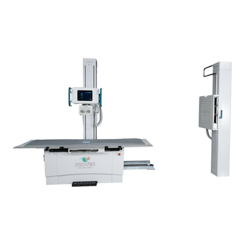
Pro-tec PROGNOST XP User manual
Pro-tec
Pro-tec PRS 500 X User manual

Pro-tec
Pro-tec PRS 500 F User manual

Pro-tec
Pro-tec PRS 500 F User manual
Pro-tec
Pro-tec PROGNOST XS User manual
Pro-tec
Pro-tec PRS 500 C User manual
Pro-tec
Pro-tec PRS 500 E Instruction sheet

