Happowa Spreader 4000 User manual

2021
Rev 2.0
Happowa Oy
www.happowa.fi
USER MANUAL
Acid applicator
Spreader 4000 & Spreader 6000

2 3
Contents
Eu Declaration of conformity................................................3
1. Safety...........................................................................................4
1.1 General safety instructions ................................................... 4
1.2 Handling of acids ........................................................................5
1.3 Personal protection ...................................................................5
1.4 First aid instructions ................................................................ 6
1.5 Restrictions on use.................................................................... 6
2. Technical specifications......................................................7
3. Assembly ..................................................................................8
3.1 Pump connection...................................................................... 8
3.2 Connecting cable...................................................................... 9
3.3 Controller connection ............................................................ 9
4. Controller usage and key functions ............................ 10
4.1 Controller buttons and their functions.......................10
4.2 Default settings ........................................................................13
4.3 Changing the default settings........................................14
5. Taking into use ..................................................................... 16
5.1 Testing..............................................................................................17
6. Additional equipment ....................................................... 18
7. Maintenance and storing ................................................. 19
8. Trouble shooting................................................................. 20
9. Terms of guarantee.............................................................22
10. Responsibilities...................................................................23
Spare parts................................................................................. 24
Eu Declaration of conformity
Happowa Oy
Kankaantie 563, 62150 Ylihärmä
We declare under our sole responsibility that the acid
applicators Spreader 4000 and Spreader 6000 starting
from production number 3200 are in conformity with the
relevant Union legislation Machinery Directive 2006/42/
EC.
These products are also in conformity with the relevant
safety requirements of the following directives:
Directive 89/392/EEC
Directive 91/368/EEC
Directive 93/44/EEC
Directive 93/68/EEC
The following standards have also been considered in
designing the products, as applicable:
EN 292-1
EN 292-2
EN 294
EN 349
EN 811
EN 1152
SFS 5091
In Ylihärmä 4.1.2019
__________________________
Johannes Holkkola, managing director

4 5
1. Safety
Spreader acid applicators are primarily intended for
pumping and dosing fluid agricultural preservatives in
silage production. The pump feeds the preservative to
the nozzles through the hoses and the preservative is
mixed to the fodder by the nozzles.
The acid applicator can also be used as a transfer pump,
in which case the pump feeds the preservative straight
to another container through the hose.
1.1 General safety instructions
• In addition to the instructions given in the manual,
you must obey all the general safety rules concerning
mechanical working.
• Before using the applicator, make sure that the device
has been connected correctly and that covers are at
place.
• Before using the applicator, make sure that all the
hoses, couplings and nozzles connected to the system
are suited for the preservatives used.
• All operating personnel must be familiar with the
operating functions and the manual of this machine.
• Keep children and unauthorised people away while
using, assembling or maintaining the machine.
• Always stop the tractor prior to maintenance or
repairs. Apply the parking brake, remove the ignition
key and disconnect the dosing machine before
leaving the cab.
• Keep the rear window of the tractor closed while
using the acid applicator.
• Always keep enough clean rinse water on hand.
• Pump a large amount of clean water through the
system before maintenance. Always handle acids with
caution. Always use acceptable personal protective
equipment.
• Inspect the condition of the hoses and the couplings
regularly. Replace any damaged parts with new ones
immediately. Notice that even a small detrition or
corrosion may cause danger.
1.2 Handling of acids
• Familiarise yourself with the safety and handling
instructions of the preservative manufacturers.
• Always handle the acid applicator with caution and
use appropriate personal protective equipment.
• Only use the acid applicator outdoors or in spaces
with adequate ventilation.
• An acid applicator that has not been cleaned can only
be placed on a surface that is acid resistant.
1.3 Personal protection
• Use an appropriate respirator if ventilation is
inadequate.
• Use tight-fitting safety goggles to protect your eyes
and keep clean water in a bottle for rinsing out eyes.
• Use protective clothing or an apron of a sufficient size
and boots to protect from any splashing.
• Use neoprene or PVC gloves to protect hands.

6 7
1.4 First aid instructions
• Inhalation of acid fumes: move to fresh air, keep warm
and calm. Consult a doctor if necessary.
• Acid splashing on skin: rinse splashes from the skin
immediately using plenty of water and take off
stained clothes.
• Acid exposure to eyes: rinse eyes immediately with
plenty of water, also under the eyelids. Consult a
doctor.
• If acid gets into mouth: rinse your mouth immediately
with plenty of water. A few glasses of water may be
drunk. Consult a doctor if necessary.
1.5 Restrictions on use
• The operator of the acid applicator must not be
under the influence of narcotics, alcohol or powerful
medications.
• In case of illness or disablement, the operation of
the machine must be authorized by the attending
physician.
• The acid applicator must not be used dry.
• Pumping inflammable liquids, liquids for human
consumption, or additives is forbidden.
• Do not pump acid that has been diluted with water
unless specifically permitted by the manufacturer.
2. Technical specifications
You can find the identity information of the machine in
the machine plate shown in the picture below. With this
information it is easier to maintain the product and order
spare parts.
Type the information of your machine to the pattern
below to be able to find it easily.
Spreader 4000 Spreader 6000
Operating voltage 12 V 12 V
Max. required
current 7 A 13 A
Max. pressure 3 bar 3 bar
Max. pumping
capacity 6 l/min 12 l/min
Weight 3,1 kg 3,1 kg
8 9
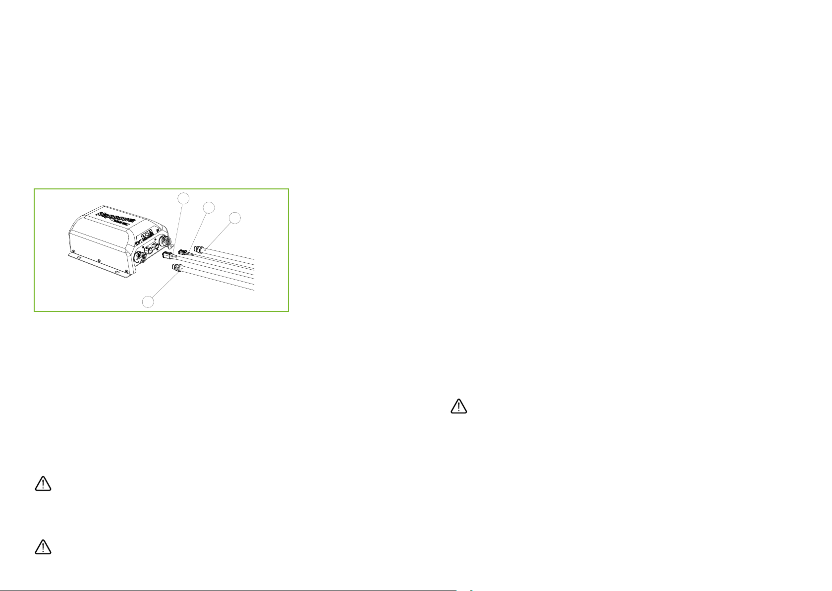
3. Assembly
3.1 Pump connection
The pump unit should be mounted as near the tank
as possible. This improves the functions of the pump
especially with a tank that is not full and after filling it
up. The pump unit can be mounted either horizontally or
vertically (couplings downwards only).
Mount the pump unit firmly with four hex head screws to
a suitable place where it is not exposed to unnecessary
vibration.
Connect the suction hose (1), limit switch (2, additional
equipment), power cable (3) and pressure hose (4) to
the analogous couplings of the pump. Make sure that
the quick couplings of the hoses are locked, and the
couplings of the power cables are firmly attached.
MAKE SURE THAT ALL THE HOSES, COUPLINGS AND
NOZZLES CONNECTED TO THE SYSTEM ARE SUITED FOR
THE PRESERVATIVE USED.
DO NOT USE THE PUMP DRY
3.2 Connecting cable
The sequence of the pins of the cable connecting the
pump to the controller:
1. Motor + 12 V
2. +10 V to the sensor
3. Flow meter signal
4. Limit switch signal
5. Sensor 0 V
6. Motor –
3.3 Controller connection
Mount the controller securely into the cabin so that it is
not exposed to unnecessary vibration. Connect the cable
and the limit switch (optional). The limit switch may be
connected either to the pump or to the controller.
Connect the controller’s power cable to the tractor’s
tripolar power outlet (red +, yellow –), the voltage of the
fuse being max. 15 A.
INCORRECT WIRING MAY DAMAGE THE
CONTROLLER!

10 11
3 4 5 6 7 8
1 2
10
9
11
12
13
14
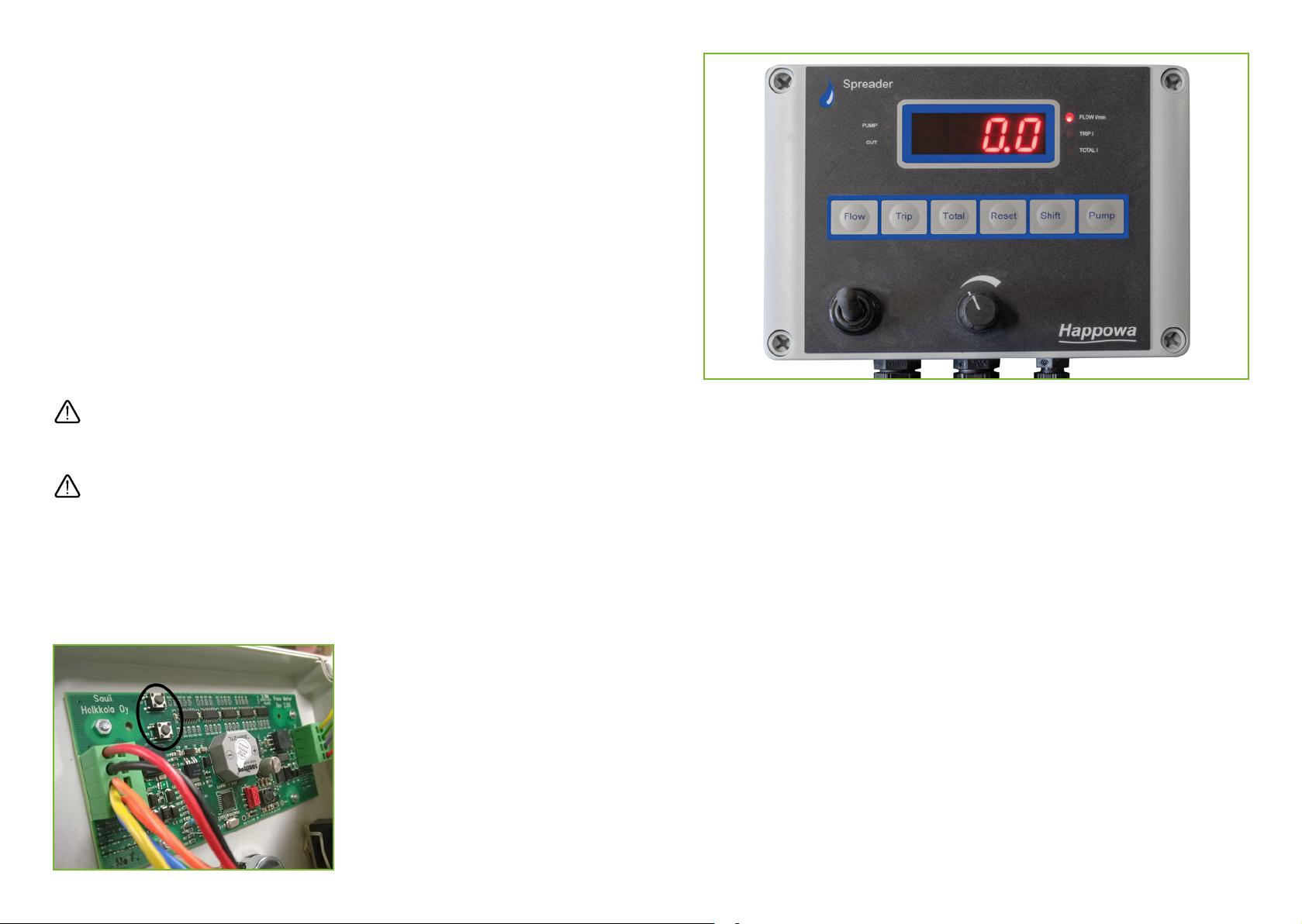
4. Controller usage and key functions
4.1 Controller buttons and their functions
1. On/off -switch
2. Power adjustment
3. Flow button
4. Trip button
5. Total button
6. Reset button
7. Shift button
8. Pump: start/stop
9. Pump: signal light
10. Limit switch: signal light
11. Digital display
12. Flow: signal light
13. Trip: signal light
14. Total: signal light
As the controller is switched on using the on/off
switch (1), the default settings are displayed in the
following order:
- The pulse rate of the flow, pulses/litre
- The level of flow alarm, litres/minute
- The hysteresis of flow alarm, litres/minute
After this the controller enters the basic mode and is
ready to operate.
The Flow button (3) is used to choose the flow metre. The
reading on the screen shows the actual liquid flow (litres/
minute) and the signal light ”Flow” (12) is on.
The Trip button (4) is used to observe the amount of
pumped litres. The number on the screen shows the
amount of pumped litres and the signal light ”Trip” (13)
is on. The calculator can be reset to zero by pressing the
Reset button (6) for 3 seconds. The Trip calculator can be
used e.g. for monitoring the consumption of preservative
per load.
The Total button (5) is used to switch on the Total
calculator that shows the amount of the pumped liquid
in litres while the signal light ”Total” (14) is on. The
calculator can be reset to zero by pressing the Reset
button (6) for 3 seconds. The Total calculator can be used
e.g. for monitoring the consumption of preservative per
container.

12 13
When the Shift button (7) is pressed and held down the
pump operates with full power regardless of the power
adjustments and the position of the limit switch. Can be
used e.g. for removing air from the system.
The Pump button (8) is used to start or stop the
pumping. When the pump is switched on the signal light
”Pump” (9) is on. The power may be adjusted steplessly
with the potentiometer (2).
If the limit switch gets activated the signal light ”Cut”
(10) is switched on and the pumping stops. As the limit
switch is released the signal light is switched off and the
pumping continues according to the adjustments.
Flow alarm
When the flow lowers below the alarm level the
controller gives the alarm signal. The buzzer goes off and
the text ”FLO” flashes on the screen. If the increase of the
flow does not reach the hysteresis level in ten seconds,
the controller automatically stops the pump. In this
case the buzzer goes out and the text ”FLO” stays on the
screen. Usually the alarm is caused by the draining of the
container. If there is still preservative left in the container,
see chapter “Trouble shooting” (p. 20).
The new
pulse rate
The amount calculated by the controller
The actual amount of litres pumped
The current
pulse rate
×
=
4.2 Default settings
PULSE RATE
The pulse rate indicates the amount of pulses in one
litre of liquid. The pulse rate has been calibrated in the
factory. If the flow calculators of the controller do not
correspond to the actual consumption, the pulse rate
can be adjusted as follows:
Check the current pulse rate. Reset the Trip calculator to
zero and pump plenty of liquid (e.g. 100 litres) through.
The new pulse rate can be calculated by comparing the
amount calculated by the controller to the the actual
amount using the following formula:
After changing the pulse rate, the reading of the Trip
calculator should indicate the actual amount of litres
pumped.
THE LEVEL OF FLOW ALARM
The default setting of the flow alarm is 1,5 l/min. If the
flow decreases below the set level for more than five
seconds, the alarm will be activated.
14 15
THE LEVEL OF HYSTERESIS
The level of hysteresis indicates the amount of increase
in the flow above the alarm level required to stop the
alarm automatically. The default setting is 0,3 l/min. In
the default setting mode, the flow alarm will be activated
when the flow decreases below 0,5 l/min for more
than five seconds. It will be deactivated when the flow
increases by more than 0,8 l/min.
4.3 Changing the default settings
To change the default settings, open the plastic case of
the controller.
Turn the power off using the on/off switch prior to
opening the case!
Proceed with great caution!
Behind the controller’s circuit card there are two
programming buttons that can be used to change the
default settings. See the picture.
Pulse rate HysteresisAlarm level
-+-+-+
The default settings can be changed by obeying the
following instruction:
1. Press both programming buttons and hold them down.
Switch on the controller by using the on/off switch.
2. Set new values using the buttons of the panel on the
front.
• Flow: the pulse rate decreases
• Trip: the pulse rate increases
• Total: the alarm level decreases
• Reset: the alarm level increases
• Shift: the hysteresis decreases
• Pump: the hysteresis increases
3. Release the programming buttons.

16 17
5. Taking into use
Connect the hoses between the pump unit and the
suction pipe and between the pump unit and the
nozzles. Mount the anti-drip valve as near the nozzles as
possible. The direction of flow is indicated by the arrow
on the valve frame.
Choose the nozzles according to the amount of litres you
are going to pump. With nozzles too large the flow may
be distributed unevenly which may weaken the power of
the flow. With nozzles too small the counter pressure of
the system increases, and the desired flow level may not
be achieved. The liquid may also disperse into spray that
is easily blown away by the wind.
The acid applicator is equipped with a pressure switch.
If the pressure of the system increases above the set
level, the pressure switch will stop the pump. The default
setting of the pressure switch is 3 bars.
5.1 Testing
Prior to acid pumping the system must be tested by
pumping clean water through the pump. The testing is
easier to do after the pump has been mounted to the
harvesting machine as the conditions are then similar to
the actual use.
The following should be observed during the pumping
test:
- The operating of the pump
- The operating of the flow sensor
- The evenness of the distribution of the flow from the nozzles
- The durability of the equipment and all the joints
A test run is also recommended prior to the beginning of
the harvest season.

18 19
6. Additional equipment
Different kinds of limit switches can be used to control
the operating of the Spreader applicators. There are
three options: a mechanical limit switch, a magnetic limit
switch and a control relay.
The limit switch can be mounted e.g. to the pick-up of
the silage machine.
A control relay can be used if there is an available signal
coming from the silage machine for controlling the
applicator. Check the availability of signal in the manual
of the silage machine.
The limit switch can be connected either to the controller
or to the pump’s limit switch coupling.
NB: Only use the original components.
NB: Supplying the limit switch coupling with voltage not
allowed!
7. Maintenance and storing
The acid applicator must always be cleaned after use
by pumping clean water through the whole system.
External cleaning is also necessary. During cleaning, the
electronic components must be protected from water.
After cleaning, the pump and the electric couplings must
be carefully dried.
Do not use a pressure washer for cleaning the pump!
Use the appropriate personal protective equipment!
After use the acid applicator must be stored in a dry
place, protected from sunlight. If the acid applicator
is stored in a cold place, pump antifreeze through the
system before storing to prevent freezing.

20 21
8. Trouble shooting
Error Possible cause Solution
The pump does
not start.
The pump is out of
power.
The limit switch is
activated.
Check the power
cables and
couplings.
Release the limit
switch.
The pump starts
but then stops
immediately.
The counter
pressure is too high.
The pressure switch
stops the pump.
Remove the
possible block,
check the mounting
of the quick coup-
lings or widen the
nozzles.
There is no
suction.
A block in the
suction filter.
Air in the suction
pipe.
The suction fails
because of small
output caused by a
long suction hose.
The valves are worn
out.
Clean the filter.
Check the condition
of the suction pipe
and the joints.
Press the Shift
button and hold it
down until the the
suction begins.
Change the valves.
Error Possible cause Solution
The output is
weak.
The valves are worn
out.
The counter
pressure is too high.
Change the valves.
Remove the
possible block,
check the mounting
of the quick coup-
lings or widen the
nozzles.
“FLO” alarm. Flow alarm, flow
below the alarm
level
The controller does
not receive the
pulse data from the
flow sensors.
Make sure there is
still liquid left in the
container.
Remove the cause
of the counter
pressure.
Adjust the alarm
level.
Check the wires
and the couplings.
Damaged flow
sensor.
(Deactivating the
FLO-alarm: Set the
alarm rate to 0.)
“ERR1” alarm. Short circuit in the
sensors.
Check the wires and
the couplings.

22 23
9. Terms of guarantee
• The warranty period for the machines manufactured
by Happowa Oy is 12 months.
• The warranty period begins on the date the
authorized dealer has delivered the new equipment.
• Warranty covers manufacturing and material defects.
• Damaged parts that have been made a complaint
about during the warranty period will be replaced
or repaired free of charge if they are returned to the
manufacturer, the shipping paid by the customer.
• The parts that have not been manufactured by
Happowa Oy, such as the circuit cards and electric
motors, are covered by the warranty of the supplier in
question.
• Warranty does not cover the operating and travelling
expenses.
• Warranty is only valid if the fault has been reported to
our dealer within 14 days from the delivery date.
Warranty does not cover:
• Damages caused by normal wear or incorrect
maintenance.
• Damages caused by incorrect use.
• Repairs or changes made without the consent of the
manufacturer and the damages caused by them.
• Secondary damages and the financial losses caused
by them.
• Damages caused by incorrect wiring.
Subject to change without notice.
10. Responsibilities
Manufacturer is not responsible if the acid applicator
is used contrary to safety regulations or this operating
manual. Since the use of the acid applicator may
cause situations for which there are no instructions or
regulations, the operators are recommended to follow
general machine safety instructions and directives.
Note that the incorrect use of acid may cause harm
to people, animals, bodies of water and soil. Follow
the instructions provided by the manufacturer of the
preservative and other experts regarding the handling
and use of preservatives.
Manufacturer is not responsible for the incorrect use of
preservatives or secondary damages caused by it.
Manufacturer is not responsible for damages caused by
the use of components manufactured by others.
Manufacturer is not responsible for damages to
other machines or equipment caused by the use of
preservatives.
The owner of the machine is responsible for its use, care
and maintenance.
The owner of the machine is responsible for making
sure that all people using the machine are sufficiently
informed of its handling and use.
Since the manufacturer cannot supervise the use
of the products we can only guarantee their quality. We
cannot take responsibility for the performance of the
products.

24 25
Spare parts 103410 103420
1
2
3
4
5
Svenska
Pcs
Part
Suomi
Code
English
5 328945
Letkunkiristin 13-20 +RVHFODPS .OlPPDUH
2
4 337113
Pikaliitinpistoke 12 mm 6QDSFRXSOLQJPDOH 6QDEENRSSOLQJPDQ
2
3 322008
Spreader välikaapeli &DEOH .DEHO
1
2 322005
Spreader -ohjain &RQWUROOHU .RQWUROOHU
1
1 337440
Spreader4000 pumppuyksikkö 3XPSXQLW 3XPSKHW
1
Dimensions
103410
Spreader 4000 pumppupaketti
1
2
3
4
337440
322005
322008
337113
328945
Spreader-ohjain
Spreader 4000 -pumppuyksikkö
Spreader-välikaapeli
Pikaliitinpistoke 12 mm
Letkunkiristin 13-20 mm
Spr. 4000 pump unit
Spreader controller
Spreader jumper cable
Quick coupling plug 12 mm
Hose clamp 13-20 mm
Spr. 4000-pumpenhet
Spreader-kontroller
Spreader-mellankabel
Snabbstickkontakt 12 mm
Slangklämma 13-20 mm
1
1
1
2
2
Osa
Nr.
Tunnus
Code
Suomi English Svenska Kpl.
Pc.
St.
5
1
2
3
4
5
Svenska
Pcs
Part
Suomi
Code
English
5 328945
Letkunkiristin 13-20 +RVHFODPS .OlPPDUH
2
4 337113
Pikaliitinpistoke 12 mm 6QDSFRXSOLQJPDOH 6QDEENRSSOLQJPDQ
2
3 322008
Spreader välikaapeli &DEOH .DEHO
1
2 322005
Spreader -ohjain &RQWUROOHU .RQWUROOHU
1
1 337460
Spreader 6000 pumppuyksikkö 3XPSXQLW 3XPSKHW
1
Dimensions
103420
Spreader 6000 pumppupaketti
1
2
3
4
337460
322005
322008
337113
328945
Spreader-ohjain
Spreader 6000 -pumppuyksikkö
Spreader-välikaapeli
Pikaliitinpistoke 12 mm
Letkunkiristin 13-20 mm
Spr. 6000 pump unit
Spreader controller
Spreader jumper cable
Quick coupling plug 12 mm
Hose clamp 13-20 mm
Spr. 6000-pumpenhet
Spreader-kontroller
Spreader-mellankabel
Snabbstickkontakt 12 mm
Slangklämma 13-20 mm
1
1
1
2
2
Osa
Nr.
Tunnus
Code
Suomi English Svenska Kpl.
Pc.
St.
5

26 27
1
2
3
4
5
6
Svenska
Pcs
Part
Suomi
Code
English
6 111651
Pvc-letku 12mm 3YFKRVH 3YFVODQJ
1
5 328945
Letkunkiristin13-20 +RVHFODPS .OlPPDUH
6
4 337113
Pikaliitinpistoke 12 mm 6QDSFRXSOLQJPDOH 6QDEENRSSOLQJPDQ
1
3 113240
Tippumisenestoventtiili 12mm &KHFNYDOYH $QWLGURSYHQWLO
1
2 337112
Pikaliitinrunko 12mm 6QDSFRXSOLQJIHPDOH 6QDEENRSSOLQJNYLQ
2
1 337006
Imuputki 6XFWLRQKRVH 6XJVODQJ
1
Dimensions
320018
Spreader varustepaketti
1
2
3
4
5
337006
337112
113240
337113
328945
Imuputki
Pikaliitinrunko 12 mm
Tippumisenestoventtiili 12 mm
Pikaliitinpistoke 12 mm
Letkunkiristin 13-20 mm
Suction pipe
Quick coupling male
Anti-drip valve 12 mm
Quick coupling plug 12 mm
Hose clamp 13-20 mm
Sugrör
Snabbkoppling hane
Droppstoppsventil 12 mm
Snabbstickkontakt 12 mm
Slangklämma 13-20 mm
1
2
1
1
6
Osa
Nr.
Tunnus
Code
Suomi English Svenska Kpl.
Pc.
St.
6111651 Pvc-letku 12 mm Pvc-hose 12 mm Pvc-slang 12 mm 1
320018 337440
16
1718
1
2
3
4
5
67
8
9
10
11
12
13
14
15
Svenska
Pcs
Part
Suomi
Code
English
18
SH1211144
Konekilpi 7\SHSODWH 7\SVN\OW
1
17
SH1902152
Spreader 4000 tarra 6WLFNHU .OLVWHUPlUNH
1
16
SH1211142
Varoitustarra 6WLFNHU .OLVWHUPlUNH
1
15 337027
Kansi &RYHU 3ODVWORFN
1
14 133020
Lukitusmutteri M6 1XW 0XWWHU
4
13 133028
Aluslatta M6 :DVKHU %ULFND
4
12 111651
Pvc-letku 12mm 3YFKRVH 3YFVODQJ
1
11 328945
Letkunkiristin13-20 +RVHFODPS .OlPPDUH
6
10 142210
Sähkösarja (OHFWULFNLW (OHNWULVNNLW
1
9 133141
Levyruuvi 3,5 x 9,5 6FUHZ 6NUXY
4
8 337109
Pikaliitinrunko 12mm 6QDSFRXSOLQJIHPDOH 6QDEENRSSOLQJNYLQ
2
7 113146 Kuusioruuvi M6 x 30 6FUHZ 6NUXY 4
6 133143
Uraruuvi M5 x 10 6FUHZ 6NUXY
6
5 113230
Virtausanturi )ORZVHQVRU )O|GHVVHQVRU
1
4 111651
Pvc-letku 12mm 3YFKRVH 3YFVODQJ
2
3 337017
Pohjalevy )RXQGDWLRQSODWH %RWWHQSODWWD
1
2 157206
Letkulähtö 12mm +RVHFRXSOLQJ 6ODQJVOXWQLQJ
2
1 157350
Kalvopumppu 2 mäntää 0HPEUDQHSXPS 0HPEUDQSXPS
1
Dimensions
337440
Spreader 4000 pumppuyksikkö
1
2
3
4
5
6
7
8
9
10
11
12
13
14
15
16
157350
157206
337017
111651
113230
133143
113146
337109
133141
142210
328945
111651
133028
133020
337027
SH1211142
Kalvopumppu 2-mäntäinen
Letkulähtö 12 mm
Pohjalevy
Pvc-letku 12mm
Virtausanturi
Uraruuvi M5 x 10
Kuusioruuvi M6 x 30
Pikaliitinrunko 12mm
Levyruuvi 3,5 x 9,5
Liitinpaneeli
Letkunkiristin 13-20 mm
Pvc-letku 12 mm
Aluslevy M6
Lukitusmutteri M6
Kansi
Varoitustarra
2-piston diaphragm pump
Hose coupling 12 mm
Bottom plate
Pvc-hose 12 mm
Flow sensor
Slot headed screw M5 x 10
Hexagonal bolt M6 x 30
Quick coupling plug 12 mm
Screw 3,5 x 9,5
Connector panel
Hose clamp 13-20 mm
Pvc-hose 12 mm
Washer M6
Nut M6
Lid
Warning sticker
2-kolvs memranpump
Slangkoppling 12 mm
Bottenplatta
Pvc-slang 12 mm
Flödesgivare
Spårskruv M5 x 10
Sexkantsskruv M6 x 30
Snabbstickkontakt 12 mm
Skruv 3,5 x 9,5
Kopplingsbord
Slangklämma 13-20 mm
Pvc-slang 12 mm
Bricka M6
Mutter M6
Lock
Varningsdekal
1
2
1
2
1
6
4
2
4
1
6
1
4
4
1
1
Osa
Nr.
Tunnus
Code
Suomi English Svenska Kpl.
Pc.
St.
17
18
SH1902152
SH1211144
Spreader 4000 -tarra
Konekilpi
Spreader 4000 sticker
Machine plate
Spreader 4000 -dekal
Märkplåt
1
1

28 29
337460
1
2
3
4
337122
337124
337122
337126
Pumpun pääty
Alempi pumpunpesä
Pressure switch
Pump end mounting
Valve set, 2-piston
Lower pump housing
Tryckbrytare
Pumpbotten
Ventilserie, 2-piston
Nedre pumphus
1
1
1
1
Osa
Nr.
Tunnus
Code
Suomi English Svenska Kpl.
Pc.
St.
1
2
3
4
337122
337134
337132
337136
Pumpun pääty
Alempi pumpunpesä
Pressure switch
Pump end mounting
Valve set, 2-piston
Lower pump housing
Tryckbrytare
Pumpbotten
Ventilserie, 2-piston
Nedre pumphus
1
1
1
1
Osa
Nr.
Tunnus
Code
Suomi English Svenska Kpl.
Pc.
St.
1234 5
Svenska
Pcs
Part
Suomi
Code
English
5 337130
Moottori
1
4 337136
Alempi pumpunpesä
1
3 337132
Venttiilisarja 4 mäntää
1
2 337134
Pumpun pääty
1
1 337122
Painekytkin
1
Dimensions
157352
Kalvopumppu 4 mäntää
12345
Svenska
Pcs
Part
Suomi
Code
English
5 337120
Moottori
1
4 337126
Alempi pumpunpesä
1
3 337122
Venttiilisarja 4 mäntää
1
2 337124
Pumpun pääty
1
1 337122
Painekytkin
1
Dimensions
157350
Kalvopumppu 2 mäntää
5
5
Moottori Engine Motor 1
Moottori Engine Motor 1
337120
337130
Painekytkin
Painekytkin
Venttiilisarja 2-mäntäinen
Venttiilisarja 4-mäntäinen
157350
157352
1
2
3
4
5
6
7
8
9
10
11
12
13
14
15
16
17
18
Svenska
Pcs
Part
Suomi
Code
English
18
SH1211144
Konekilpi
1
17
SH1902153
Spreader 6000 tarra
1
16
SH1211142
Varoitustarra
1
15 337027
Kansi
1
14 133020
Lukitusmutteri M6
4
13 133028 Aluslatta M6 4
12 111651
Pvc-letku 12mm
1
11 147151
Klemmari 12-22
6
10 142210
Sähkösarja
1
9 133141
Levyruuvi 3,5 x 9,5
4
8 337109
Pikaliitinrunko 12mm
2
7 113146 Kuusioruuvi M6 x 30 4
6 133143
Uraruuvi M5 x 10
6
5 113230
Virtausanturi
1
4 111651
Pvc-letku 12mm
2
3 337017
Pohjalevy
1
2 157210
Letkuliitin 1/2"
2
1 157352
Flojet 18 R4300143
1
Dimensions
337460
Spreader 6000 pumppuyksikkö
7\SHSODWH 7\SVN\OW
6QDEENRSSOLQJNYLQ
6WLFNHU .OLVWHUPlUNH
6WLFNHU .OLVWHUPlUNH
&RYHU 3ODVWORFN
1XW 0XWWHU
:DVKHU %ULFND
3YFKRVH 3YFVODQJ
+RVHFODPS .OlPPDUH
(OHFWULFNLW (OHNWULVNNLW
6FUHZ 6NUXY
6QDSFRXSOLQJIHPDOH
6FUHZ 6NUXY
6FUHZ 6NUXY
)ORZVHQVRU )O|GHVVHQVRU
3YFKRVH 3YFVODQJ
)RXQGDWLRQSODWH %RWWHQSODWWD
+RVHFRXSOLQJ 6ODQJVOXWQLQJ
0HPEUDQHSXPS 0HPEUDQSXPS
1
2
3
4
5
6
7
8
9
10
11
12
13
14
15
16
157352
157210
337017
111651
113230
133143
113146
337109
133141
142210
147151
111651
133028
133020
337027
SH1211142
Kalvopumppu 4-mäntäinen
Letkuliitin 1/2”
Pohjalevy
Pvc-letku 12 mm
Virtausanturi
Uraruuvi M5 x 10
Kuusioruuvi M6 x 30
Pikaliitinrunko 12mm
Levyruuvi 3,5 x 9,5
Liitinpaneeli
Klemmari 12-22 mm
Pvc-letku 12 mm
Aluslevy M6
Lukitusmutteri M6
Kansi
Varoitustarra
4-piston diaphragm pump
Hose coupling 1/2”
Bottom plate
Pvc-hose 12 mm
Flow sensor
Slot headed screw M5 x 10
Hexagonal bolt M6 x 30
Quick coupling plug 12 mm
Screw 3,5 x 9,5
Connector panel
Hose clamp 12-20 mm
Pvc-hose 12 mm
Washer M6
Nut M6
Lid
Warning sticker
4-kolvs memranpump
Slangkoppling 12 mm
Bottenplatta
Pvc-slang 12 mm
Flödesgivare
Spårskruv M5 x 10
Sexkantsskruv M6 x 30
Snabbstickkontakt 12 mm
Skruv 3,5 x 9,5
Kopplingsbord
Slangklämma 12-20 mm
Pvc-slang 12 mm
Bricka M6
Mutter M6
Lock
Varningsdekal
1
2
1
2
1
6
4
2
4
1
6
1
4
4
1
1
Osa
Nr.
Tunnus
Code
Suomi English Svenska Kpl.
Pc.
St.
17
18
SH1902153
SH1211144
Spreader 6000 -tarra
Konekilpi
Spreader 6000 sticker
Machine plate
Spreader 6000 -dekal
Märkplåt
1
1

30 31
1
2
3
4
5
6
Svenska
Pcs
Part
Suomi
Code
English
6 337108
Pikaliitinpistoke 3/8" 6QDSFRXSOLQJPDOH 6QDEENRSSOLQJPDQ
1
5 320032
Tynnyrisovite&DS.RUN
1
4 111651
Pvc-letku 12mm 3YFKRVH 3YFVODQJ
1
3 328990
Letkunkiristin A4 12-22 +RVHFODPS .OlPPDUH
2
2 313287
Letkuliitin 3/8" -13mm +RVHFRXSOLQJ6ODQJVOXWQLQJ
2
1 337202
Imusihti koottu 6WDLQHU 6LO
1
Dimensions
337006
1
2
3
4
5
337202
313287
328990
111651
320032
Imusuodatin koottu
Letkuliitin 3/8” 13mm
Letkunkiristin A4 12-22
Pvc-letku 12 mm
Tynnyrisovite
Suction filter, complete
Slangkoppling 3/8” 13 mm
Hose clamp A4 12-22
Pvc-hose 12 mm
Barrel adapter
Sugfilter, monterat
Hose coupling 3/8” 13 mm
Slangklämma A4 12-22
Pvc-slang 12 mm
Fatadapter
1
2
2
1
1
Osa
Nr.
Tunnus
Code
Suomi English Svenska Kpl.
Pc.
St.
6337108 Pikaliitinpistoke 3/8” Quick coupling plug 3/8” Snabbstickkontakt 3/8” 1
337006
1
2
3
4
10
7
8
9
11
5
6
12
Svenska
Pcs
Part
Suomi
Code
English
12 313289
Putkiteippi 6HDOWDSH 7lWQLQJWHMS
1
11 133630
Kuusiokoloruuvi M6x40 6FUHZ 6NUXY
4
10 337420
Putken kiinnikepari 13,5mm 3LSHIDVWHQHUSDLU 5|UIlVWSDU
2
9 133028
Aluslatta M6 :DVKHU %ULFND
4
8 133020
Lukitusmutteri M6 1XW 0XWWHU
4
7 1666
Kiinnityslatta )DVWHQLJQSODWH )lVWSODWWD
2
6 313298
Viuhkasuutin 2,2 l/min 9508 1R]]OH 0XQVW\FNH
3
5 313293
Viuhkasuutin 1,1 l/min 9504 1R]]OH 0XQVW\FNH
3
4 313283
Kulmanippa$QJOHQLSSOH 9LQNHOQLSSHO
1
3 337403
Väliputki3LSH5|U
2
2 313282
T-nippa 7QLSSOH 7QLSSHO
2
1 313284
Letkuyhde +RVHFRXSOLQJ 6ODQJVOXWQLQJ
1
Dimensions
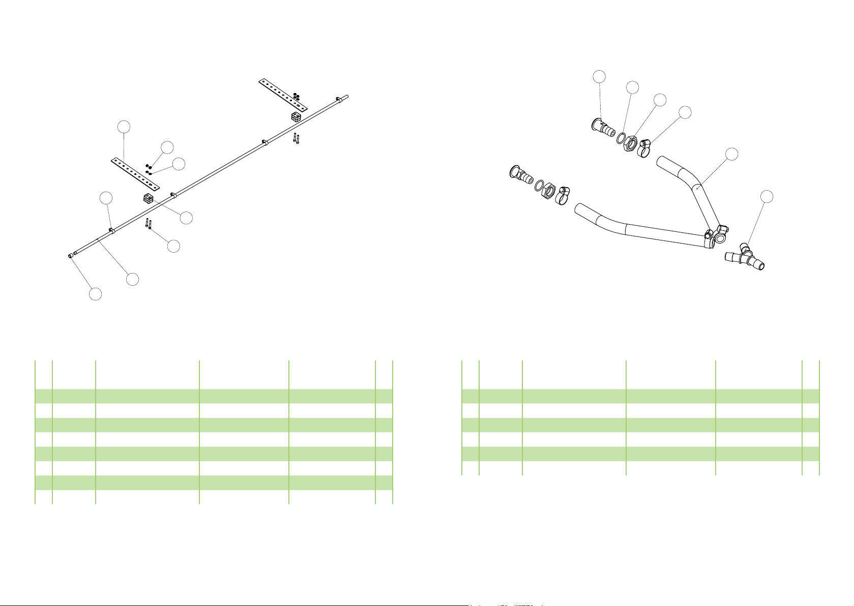
337400
Viuhkasuutintanko
1
2
3
4
5
6
7
8
9
10
11
313284
313282
337403
313283
313293
313298
1666
133020
133028
337420
133630
Letkuyhde
T-nippa
Väliputki
Kulmanippa
Viuhkasuutin 1,1 l/min 9504
Viuhkasuutin 2,2 l/min 9508
Kiinnityslevy
Lukitusmutteri M6
Aluslevy M6
Putken kiinnikepari 13,5 mm
Kuusiokoloruuvi M6x40
Hose coupling
T-adapter
Pipe
Elbow adapter
Flat spray nozzle
Flat spray nozzle
Mounting plate
Nut M6
Washer M6
Pipe fastener 13,5 mm
Hex. socket head screw
Slangkoppling
T-koppling
Rör
Vinkelkoppling
Spaltspridarmunstycke
Spaltspridarmunstycke
Fästplatta
Mutter M6
Bricka M6
Rör fästdon 13,5 mm
Sexkanthålsskruv
1
2
2
1
3
3
2
4
4
2
4
Osa
Nr.
Tunnus
Code
Suomi English Svenska Kpl.
Pc.
St.
12 313289 Putkiteippi Tape Tejp 1
337400
32 33
1
2
3
4
5
6
7
8
Svenska
Pcs
Part
Suomi
Code
English
8 303115
Asennusside +RVHFODPS .OlPPDUH
4
7 337414
Tulppa3OXJ 3URSS
1
6 337412
Pistesuutinputki3LSH5|U
1
5 133630
Kuusiokoloruuvi M6x40 6FUHZ 6NUXY
4
4 337421
Putken kiinnikepari 12mm 3LSHIDVWHQHUSDLU 5|UIlVWSDU
2
3 133028
Aluslatta M6 :DVKHU %ULFND
4
2 133020
Lukitusmutteri M6 1XW 0XWWHU
4
1 1666
Kiinnityslatta )DVWHQLQJSODWH )lVWSODWWD
2
Dimensions
337410
Reikäsuutintanko
1
2
3
4
5
6
7
8
1666
133020
133028
337421
133630
337412
337414
303115
Kiinnityslevy
Lukitusmutteri M6
Aluslevy M6
Putken kiinnikepari 12 mm
Kuusiokoloruuvi M6x40
Pistesuutinputki
Tulppa
Klemmari
Mounting plate
Nut M6
Washer M6
Pipe fastener 12 mm
Hex. socket head screw
Spridarrör
Plug
Clamp
Fästplatta
Mutter M6
Bricka M6
Rör fästdon 12 mm
Sexkanthålsskruv
Spray bar
Propp
Klämmare
2
4
4
2
4
1
1
4
Osa
Nr.
Tunnus
Code
Suomi English Svenska Kpl.
Pc.
St.
337410
1
2
3
4
5
6
Svenska
Pcs
Part
Suomi
Code English
6 113011
6LOSSXULVXXWLQ 1R]]OH 0XQVW\FNH
2
5 144981
O-rengas 16 x 22ULQJ 2ULQJ
2
4 133116
Matala mutteri M16 x 1,5 7KLQQXW 7XQQPXWWHU
2
3 328945
Letkunkiristin13-20 +RVHFODPS .OlPPDUH
4
2 111651
Pvc-letku 12mm 3YFKRVH 3YFVODQJ
2
1 157302
T-haara7FRQQHFWRU 7NRSSOLQJ
1
Dimensions
113351
SLOSSXULVuutinsarja
1
2
3
4
5
157302
111651
328945
133116
144981
T-haara
Pvc-letku 12 mm
Letkunkiristin 13-20
Matala mutteri M16 x 1,5
O-rengas 16 x 2
T-connector
Pvc-hose 12 mm
Hose clamp 13-20
Nut M16 x 1,5
O-ring
T-koppling
Pvc-slang 12 mm
Slangklämma 13-20
Mutter M16 x 1,5
O-ring
1
2
4
2
2
Osa
Nr.
Tunnus
Code
Suomi English Svenska Kpl.
Pc.
St.
6113011 Silppurisuutin Chopper nozzle Flismaskin munstycke 2
113351

Happowa Oy
www.happowa.fi
tel. +358 400 863 514
myynti@happowa.fi
This manual suits for next models
1
Table of contents
Other Happowa Spreader manuals

Popular Spreader manuals by other brands


Cub Cadet
Cub Cadet 125 lb Spreader & 10 Gallon Sprayer Operator's manual

SnowEx
SnowEx SP-1675 owner's manual

Warren
Warren AC-1820A Owner / Operator Manual & Parts Reference Guide

Tatu Marchesan
Tatu Marchesan DCA2 MC 2500 Operator's manual

Echo
Echo RB-60 Operator's manual

Amazone
Amazone SUPER-JET 1600 H-18 Operator's manual


