Warren AC-1820A User manual

Do not operate or work on this spreader without first reading and understanding this manual.
Keep this manual with the spreader at all times. 9/2018
AC-1820A
Owner/ Operator Manual
&
Parts Reference Guide

INDEX
Preface............................................................................................................................................. 3
Ordering Repair Parts ..................................................................................................................... 3
Warranty ......................................................................................................................................... 4
General Description........................................................................................................................ 5
Hydraulic Cross Conveyor.......................................................................................................... 5
Precautions Before Spreader Operation.......................................................................................... 7
Parts List and Illustrations .............................................................................................................. 9

Keep all guards in place.
Before serving, disengage PTO and wait for all
moving parts to stop.
Do not use spinners disc for step.
Keep all loose clothing away from shafts and
spinners.
Keep hands and feet away from conveyor when in
operation.
CAUTION

3
PREFACE
This Owner/ Operator Manual &Parts Reference Guide is to assist in the correct operation and
maintenance of this spreader by providing information for installation, operation, service and
maintenance. Please read this manual thoroughly before proceeding to use the equipment.
The economic life of any piece of equipment is directly related to the care and maintenance it
receives. Use this manual as a reference in seeing that this unit receives proper care and is
correctly operated.
The use of genuine Warren parts is recommended for best equipment service as well as insuring
that our warranty policy is not voided.
If additional information is required or should you desire to have a qualified service facility work
on this spreader, contact your Warren Distributor.
ORDERING REPAIR PARTS
Contact the authorized dealer who services your area. If unknown contact Warren, Inc.
In ordering parts, be sure to have spreader model and serial number. Also have description and
part number of parts required. Be able to specify the method of shipping if parts are not to be
picked up such as UPS, Truck Line, Air Freight, or Parcel Post. If parts are ordered by phone, be
sure to confirm in writing to insure an understanding of what you need.
Inspect parts shipments immediately and notify delivering carrier as well as dealer damage or
shortage. If carrier loses or damages parts you should file a claim with them –not the dealer. The
dealer responsibility for shipment ceases when goods are turned over to the carrier.
When possible, it is good to anticipate parts requirements by having a good preventive
maintenance program having some parts on hand to take of minor requirements could be a great
convenience and could save valuable time.
Warren, Inc reserves the right to make changes in our equipment at
any time without any obligation whatsoever to change units already
in the field.

4
WARRANTY
Spreaders
WARRANTY. WARREN, INC., (herinafter called Warren) warrants each new spreader and item
of hydraulic equipment manufactured by it to be free from defects in material and workmanship
under normal use and service with loads not exceeding the vehicle manufacturer’s rated capacity for
a period of 12 months after delivery to the original purchaser direct or by and authorized distributor.
Exclusions from Warranty: This Warranty shall not apply to:
(1) components manufactured by persons other than Warren (such as hydraulics pumps, motors,
valve, bearings, etc.) beyond warranty, if any, which may be made by such manufacturer,
(2) any unit which shall have been subject to misuse, negligence, alteration or accident or which shall
have been repaired by anyone other than Warren or its authorized service distributor in any way so as
in the judgment of Warren to affect adversely its performance or reliability, or
(3) normal maintenance services.
Purchaser’s Exclusive Remedies. Warren’s sole obligation under this warranty will be to repair or
replace. At its option, any warranted unit or part as described above which shall be returned to
Warren’s factory or authorized service distributor and which examination shall disclose to Warren’s
satisfaction to have been defective. Freight or other transportation costs to and from the factory or
authorized service distributor must be paid by the purchaser. Warren will not assume any charges for
repairs made by anyone other than Warren or its authorized service distributor.
Exclusion of other Warranties. No other warranty is made by Warren and in particular Warren
makes NO WARRANTY OF MERCHANABILITY OR FITNESS FOR ANY PARTICULAR
PURPOSE. Warren neither assumes nor authorizes any person to assume for it any liability other
than described herein.
Limitations of Actions. Without extending the period of warranty stated above, any action for
breach of warranty must be commenced within one year of the breached claimed or forever barred.
Limitations of Damages. The purchaser’s remedy stated above shall be exclusive for any claims
against Warren whether based on contract, negligence, tort, or any other theory. In no event shall
Warren be liable for any consequential damages which may result from any defect or failure of a unit
or part.
Warren, Inc.
707 North Fir Ave., P.O. Box 1719, Collins MS 39428
Phone: (601) 765-4554 Fax: (601) 765-4554

5
GENERAL DESCRIPTION
The units required under these specifications shall be mounted to the side of the dump body,
below floor level and beneath the tailgate. During the maintenance operations it shall permit the
dumping of materials to the left or right without interfering with the operation of the tailgate.
The conveyor shall be capable of being controlled by the truck hydraulic system to vary the
amount of material being conveyed to the roadway surface. Bidders must submit with bids
complete detailed specifications on the units they propose to furnish. Bids with exceptions to
these specifications shall be considered unresponsive. Shall be capable of right or left discharge
Has 18” belt over chain D667X , 96” wide riveted, with 3/8”x1-1/4” crossbars, H.D. hot asphalt
type to withstand heat of 350 degrees Fahrenheit. Reversible with hydraulic hoses. Discharge
gates to be rack & pinion and shall be located on left and right sides of spreader. Feed gate
openings 16-1/4”x13” minimum. 6 tooth drive and idler sprockets flame cut steel plate, keyed
and timed with 1-1/2” shafts. ¼” wiper belting seals off front and rear end panels to conveyor.
Hydraulic reservoir and filter, hydraulic quick disconnect couplings, hydraulic hose and fitting
for truck and spreader, hydraulic in cab control valve and hydraulic pump. Pin mount type using
four pins for quick disconnect.
Optional Attachments:
Spinner attachment for spreading.
HYDRAULIC CROSS CONVEYOR
MOUNTING INSTRUCTIONS FOR AC-1820A
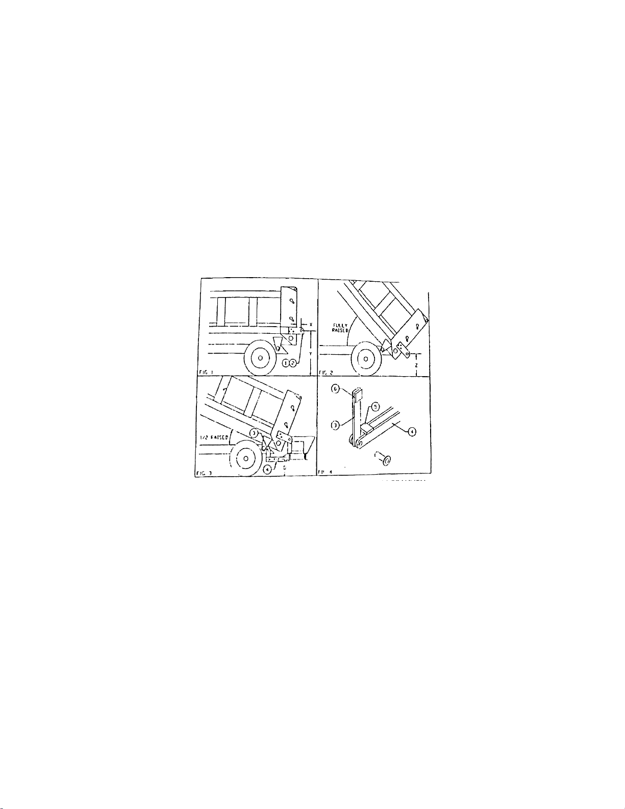
STEP 1. Place one inside upper mounting bracket, (Fig. 1, Item 1, Part No. 200536-19), on side
of the dump box rub rail with the bot- tom edge of the bracket even with the bottom edge of the
rub rail. Measure 2 1/2" from the back of the dump box to the center of the 1" hole in bracket, X,
and clamp bracket in place. Drill three 1/2" holes in the dump box to match the holes in the
bracket. Repeat this process for the other side of the dump box. Using the 1/2" x2 1/2* bolts in
the shipping kit, insert bolt from the inside of the rub rail outward. Attach the bracket to the
dump box with a lock washer and nut. Measure the outside distance between both brackets,
keeping this distance approximately 1/4" greater than the inside distance between the end panels
of the cross conveyor. The brackets may need to be spaced out evenly on both sides to attain the
proper distance. Before tightening down the inside brackets, place a flat washer on each bolt and
attach the outside bracket, (Fig. 1, Item 2, Part No. 200536-18), with a lock washer and nut.
Insert the 1" pin x 2 1/4" long, Part No. 220343- 05, through the hole in the brackets and tighten
the inside nut, then the outside nut. Measure the distance from the center of the pin to the ground,
Y.
STEP 2. Raise the dump box to the top position and measure the distance from the center of the
pin to the ground, (Fig. 2, Z). Determine the angle of the dump box that is half-way between

6
fully raised and fully lowered. Lower the dump box to this degree and mount the spreader to the
truck. Be sure the spreader is level and measure the distance between the lower mounting hole
and the ground, (Fig. 3, D).
STEP 3. In the shipping kit there are 4 brackets approximately 24" long with a 1" dia. hole in
each, use the difference in the Y measurement and the Z measurement, (Fig. 3, Y-Z), to locate
the distance for drilling the second 1" dia. hole from the existing hole. If more than an inch of the
bracket is left beyond the hole, cut the extra material away to prevent any type of interference.
STEP 4. Using two of the four modified brackets, (Fig.3, Item 4, Part No. 200536-21). place one
on each side of the lower mounting plate on the front of the spreader and insert a 1" pin x 3"
long, Part No. 220343-06, through the hole securing it with a hitch pin, Part No.
FM-00518. Repeat this process for the other lower mounting plate.
CAUTION: END GATE MAY CAUSE SEVERE DAMAGE WHEN RAISING DUMP
BOX WITH MATERIAL IN SPREADER.
STEP 5. There are 2 brackets in the shipping kit approximately 15" long with a 1" dia. hole in
each, Part No. 200536-20. Place one bracket against the truck frame and align it between the two
brackets on the lower mounting plate of the spreader. Spacers of some type may need to be used
to line up the brackets properly. Refer to Fig. 3, Item 3, and Fig. 4 for further details. Insert a 1"
pinx3" long through the hole and secure it with a hitch pin.
STEP 6. Move the shorter bracket along the frame until the distance between the hole you
drilled and the ground is the same as the measurement "D" in Fig. 3. Tack weld the bracket to the
truck frame and repeat this process for the other side. If you have the spreader leveled on
removable stands, clear all objects from underneath the spreader. Check to see if the spreader is
going to remain level by raising and lowering the dump box. If the spreader remains adequately
level, attach the brackets more securely (solid weld or bolts). If the spreader does not remain
adequately level, then break loose the tacks and raise or lower the bracket to correct for the
direction in which the spreader is unlevel. With the dump box at the fully raised position, the

7
spreader may be unlevel, but this will not cause any damage since there is little material in the
dump box at this position
STEP 7. Completely lower the dump box, then raise it until there is just over 2" of space
between the front of the dump box and the subframe. Weld stop block, (Fig. 4, Item 5, Part No.
200536-22) securely to horizontal leveling arms. The block should be in contact with the vertical
leveling bracket when the dump box is completely. lowered. This will prevent the spreader from
tilting, which could cause serious damage!
STEP8. Connect all hydraulic hoses and fittings, then check conveyor direction. If rotation is
opposite of desired direction, switch hose connections.
STEP 9. Attach rubber Hap in shipping kit to the back edge of the
dump
box. The flap should
hang inside of the spreader when the dump box is raised.
STEP 10. If asphalt is to be conveyed, spray the rubber flap and conveyor belt lightly with fuel
oil. Do not spray oil on the drive roller lagging!
AC-1820A SPECIFICATIONS
MOTOR:
The fluid pressure into the conveyor motor should be approximately 1500 psi.
The recommended flow for the conveyor motor is 20 gpm.
BELT: The conveyor belt supplied is heat and petroleum resistant. lt can withstand
temperatures of up to 350° F. The belt is also equipped with a molded guide underneath
to align the conveyor belt with the grooves in the pulleys. If the belt tends to
travel
toward one
side, then the adjustment bolt on that side may need to be tightened. The belt
tension should be checked regularly.
PRECAUTIONS BEFORE SPREADER OPERATION
Material should be loaded into the spreader by raising the dump box at intervals. Filling the
spreader continuously could cause overflow and damage the conveyor motor. Spill guards are
provided in the shipping kit to prevent material from spilling over the end panels of the spreader.
These guards may need to be modified for clearance with the feed gate opening. When operation
of the spreader is complete. we do recommend that you run the conveyor until all of the material
is removed. This will prevent accumulation in undesired areas. If material builds-up between the
tailgate and the spreader, the tailgate could apply severe pressure on the spreader causing some
damage.
WARNING!
Use extreme caution around moving parts. Keep hands and loose clothing away from spreader
while in operation.

8
LUBRICATION CHART
Description
Service Location
No.
of
Points
Method of
Lubrication
Daily
Weekly
Monthly
Semi
Annual
Gear Boxes
Conveyor
Plug side of case
1
Lube Oil
X
Universal Joints
PTO Drive Line to Hyd.
Pump
Beneath Truck
3
Grease Gun
X
Bearings
Conveyor Drive
Conveyor Idler
Both side of conveyor
drive shaft at rear
Both side of conveyor
idler shaft at front
2
2
Grease Gun
Grease Gun
X
X
Chain
Conveyor
Chain 2 strand
2
Spray Oil
X
Feed Gate Jack
Tube
Gears
Rear of tube
Top of Jack
1
1
Grease Gun
Hand Grease
X
X
Spinner
Bearing on drive shaft
1
Grease Gun
X
Lubrication Recommended:
•Gearbox - SAE 90 EP Gear Lube non-corrosive MIL - L2105B Multi-Purpose
•Grease Gun - Ball and Roller Bearings Lithium Base Grease - conforming to NLG1
number 2 consistency - Waterproof
•Spray Oil - for chain - make up of 75% #1 or #2 diesel fuel, 25% SAE 10W-40

9
PARTS LIST AND ILLUSTRATIONS
Feed Gate.......................................................................................................................................10-11
Spreader Assembly........................................................................................................................12-14

10

11

12

13

14
Table of contents