Happy Industrial Corporation HCS2 User manual

SAO512-6
INSTRUCTION BOOK
Program Ver. *1.34 ~
HCS2
Computerized Compact Single Head Embroidery Mac ine
Original instructions


-SA -3
INDEX
IMPORTANT SAFETY INSTRUCTIONS.. 1-1
WARNING LABELS & THEIR LOCATIONS .....
1-2
SETTING UP THE MACHINE
Remove the machine from box............... 2-1
Accessories ............................................ 2-2
Assemble machine unit .......................... 2-3
Machine installation ................................ 2-4
Grounding instruction ............................. 2-6
Disposal of a battery............................... 2-6
MAIN PARTS ............................................ 3-1
HOW TO READ THESE INSTRUCTIONS and SCROLLBAR
3-3
MESSAGE ................................................ 3-4
TURNING THE MACHINE ON
How to turn on the machine.................... 3-5
Calendar and clock setting ..................... 3-7
THE CONTROL BOX................................ 3-8
DRIVE MODE ........................................... 3-9
GUIDE.......................................................3-D
INSERTING A NEEDLE............................ 4-1
SELECT NEEDLES AND THREADS....... 4-2
BACKING MATERIALS............................. 4-3
BOBBIN WINDING
Winding the bobbin................................. 4-4
Removing the bobbin.............................. 4-5
Inserting the bobbin ................................ 4-5
Adjusting bobbin thread tension ............. 4-5
Inserting the bobbin case ....................... 4-5
THREADING THE MACHINE
How to thread upper thread.................... 4-6
MACHINE SETTINGS............................... 5-1
LOCK STITCHES.....................................5-3b
PREPARATION OF PATTERN DATA
Connecting to a PC ................................ 5-4
Reading embroidery pattern data from
the PC ..........................................................
5-4b
Read embroidery pattern data................ 5-5
Reading pattern data .............................. 5-6
Selection of folders ................................. 5-9
How to select patterns from memory...... 5-A
Erasing patterns from memory ............... 5-B
NEEDLE BAR SELECTION...................... 5-E
SEWING WITH TUBULAR FRAMES
Installing and removing the frame base.. 6-1
How to hoop ........................................... 6-2
Putting the hoop on the machine............ 6-3
Starting to embroider .............................. 6-4
CAP FRAME (OPTION)
Changing the needle plate...................... 7-1
Installing and removing the cap drive frame...
7-2
Normal cap frame ................................... 7-5
Wide cap frame ...................................... 7-8
Starting to embroider .............................. 7-B
ADJUSTING THE THREAD TENSIONS .. 8-1
ADJUSTING THE LASER POINTER (OPTION)...
8-2
SEWING
What to do if the thread breaks while sewing.
9-1
Stopping and resuming sewing .............. 9-1
Loss of power while embroidering .......... 9-2
Moving the hoop while embroidering and then returning to
the correct location (Position) .......................................
9-3
Moving back to the starting point (Origin)9-3
Going back to the beginning of the design (Top) ....
9-4
Placing the design in the center of the selected
embroidery frame
(Center) ..................................
9-4
Rotating and mirroring designs (Convert) ..
9-5
Starting in the middle of a design (Position)...
9-6
DISPLAYING THE PATTERN IN SETTING MODE.
10-1
PATTERN
Locking pattern data ............................. 11-1
Trace type............................................. 11-2
Export ................................................... 11-3
Renaming patterns ............................... 11-5
Copying pattern data ............................ 11-6
Moving pattern data.............................. 11-7
0_1 N401
0-1

-SA -4
INDEX 0-2
Renaming folders ................................. 11-9
Sort........................................................11-A
Thread break report...............................11-B
Retrieve built-in data from machine...... 11-C
Searching pattern data ......................... 11-D
PATTERN SETTINGS ............................ 12-1
Scaling.................................................. 12-2
Width adjustment.................................. 12-3
Angle .................................................... 12-4
Repeat sewing...................................... 12-5
Auto origin ............................................ 12-7
Offset.................................................... 12-8
Frame out ............................................. 12-D
NEEDLE BAR SELECTION .................... 13-1
Auto setting........................................... 13-2
Thread color ......................................... 13-3
Color change data registration ............. 13-5
Color change data read ........................ 13-6
Repetition of color group setting........... 13-7
READING
Join....................................................... 14-1
Pattern Read Settings .......................... 14-4
POSITION ALIGNMENT BY DEFINING 2 POINTS.
15-1
POSITION ............................................... 16-1
Piece number ....................................... 16-2
REGISTER.............................................. 17-1
Entry ..................................................... 17-2
Return................................................... 17-3
LETTER .................................................. 18-1
QUEUE ................................................... 19-1
Alter and Execution .............................. 19-2
Needle bar selection and Pattern settings...
19-4
Registration of QUEUE setting............. 19-5
Read QUEUE setting............................ 19-6
FRAME CONFIRMATION....................... 20-1
Frame selection...........................................
20-2
Adjusted for embroidery area ............... 20-4
User-defined frames (1 ~ 5).................. 20-7
User-defined frames (6 ~ 20).................20-A
How to change center point of frame (1 ~ 5, 6 ~ 20) ..
20-J
Non registered .......................................20-L
i-CUSTOM............................................... 21-1
USER MANAGEMENT
Registration of administrator................. 21-3
Registration of user .............................. 21-6
Selection of user (Login)....................... 21-8
Selection of user (Login) at power ON . 21-9
OTHER SETTINGS
Create network ..................................... 22-1
Version information............................... 22-3
Language.............................................22-3b
Calibrate .............................................. 22-3c
Report................................................... 22-4
User maintenance mode ...................... 22-5
SCREEN SAVER.................................... 22-7
SPECIFICATIONS • MAINTENANCE
Specifications ....................................... 23-1
Oiling .................................................... 23-1
Cleaning of rotary hook ........................ 23-2
Cleaning of thread cutting knife (Rev. A).....
23-2
Cleaning of thread cutting knife (Before Rev. A).
23-4
ERRORS AND WHAT TO DO ................ 24-1
INITIALIZING OF MACHINE SETTINGS
Re-Initialization of machine system ...... 25-1
Initializing of machine speed ................ 25-2
HELPFUL HINTS .................................... 26-1
EMBROIDERY TERMS .......................... 26-2
BUILT-IN FONT LIST.............................. 26-3
BUILT-IN PATTERNS LIST .................... 26-4
0_2 O212

-CS -3
IMPORTANT SAFETY INSTRUCTIONS
1_1 F201
1-1
When using an electrical appliance, basic safety precautions should always be followed, includ-
ing the following.
Read all instructions before using this appliance.
DANGER - To reduce the risk of electric shock:
1. An appliance should never be left unattended when plugged in. Always unplug this appliance
from the electric outlet immediately after using and before cleaning.
WARNING
-To reduce the risk of burns, fire, electric shock, or injury to persons:
1. Do not allow to be used as a toy. Close attention is necessary when this appliance is used
by or near children.
2. Use this appliance only for its intended use as described in this manual. Use only attach-
ments recommended by the manufacturer as contained in this manual.
3. Never operate this appliance if it has a damaged cord or plug, if it is not working properly, if it
has been dropped or damaged, or dropped into water. Return the appliance to the nearest
authorized dealer or service center for examination, repair, electrical or mechanical adjust-
ment.
4. Never operate the appliance with any air openings blocked. Keep ventilation openings of the
sewing machine and foot controller free from the accumulation of lint, dust, and loose cloth.
5. Never drop or insert any object into any opening.
6. Do not use outdoors.
7. Do not operate where aerosol (spray) products are being used or where oxygen is being
administered.
8. To disconnect, turn all controls to the off (“0”) position, then remove plug from outlet.
9. Do not unplug by pulling on cord. To unplug, grasp the plug, not the cord.
10.Keep fingers away from all moving parts. Special care is required around the sewing ma-
chine needle.
11.Always use the proper needle plate. The wrong plate can cause the needle to break.
12.Do not use bent needles.
13.Do not pull or push fabric while stitching. It may deflect the needle causing it to break.
14.Switch the sewing machine off (“0”) when making any adjustments in the needle area, such
as threading needle, changing needle, threading bobbin, or changing presser foot, etc.
15.Always unplug sewing machine from the electrical outlet when removing covers, lubricating,
or when making any other user servicing adjustments mentioned in the instruction manual.
SAVETHESE INSTRUCTIONS
-S2 -7
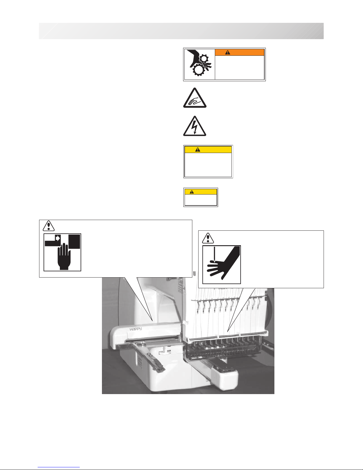
WARNING LABELS &THEIR LOCATIONS
1_2 M201
1-2
Trapping hazard
Shut the cover when starting the machine.
Do not put hands in while the machine is running.
Trapping, Puncture, Cut hazard wherever this
label is found
Shock hazard on all electrical components
Injury risk on moving head(s)
Keep hands away from the moving heads while the
machine is running.
Laser beam (Class 1)
Do not stare into the beam.
ES-HMF-5113-0
WARNING
Shut the cover when starting the
machine. Do not put hands in
while the machine is running.
Fearof serious injury.
ES-HMF-5117-0
CAUTION
Keep hands away from the
moving heads while the
machine is running.
Possibility of injury.
CAUTION: Injury risk on frame and carriage
Keep hands away from the drive
frame while the machine is
running.
Catch a finger in the X-carriage.
WARNING: Injury risk warning
for all needles
Keep fingers away from
the needles while
the machine is running.
Laser beam (Class 1)
CAUTION
Do not stare into the beam.

-BD -5
SETTING UPTHE MACHINE
2_1 K101
2-1
CAUTION: To prevent accidents.
The machine is quite heavy for one person to carry.
Please use two persons when unpacking or carrying.
CAUTION: To avoid problems.
Make sure to hold bottom of the machine body when
removing from the box.
Do not hold any other place. (bed, moving head,
control box etc.).
We recommend unpacking should be done where it has enough room.
Remove the machine from box
1. Remove 2 straps from the carton.
2. Lift the box (upper) to remove.
3. Take out the accessories.
Refer to the next page.
4. Take out the styrene foam (right) and (left).
5. Take out the styrene foam (lower front),
(lower right), and (lower left).
Be careful not fall down the machine, tilt the
machine slightly when taking out the styrene
form (lower right) and (lower left).
6. Carry the machine to installation location.
Please keep those packing materials in
case of necessary for repair or other rea-
sons.
Packing procedure is the reverse from
unpacking procedure.
Straps
Box (upper)
Styrene foam
(lower front)
Styrene foam
(lower right)
Styrene foam
(lower left)
How to carry machine
The unpacked machine should be carried by 2 person with the hand position at mark shown
in photos. Right side Left side
The person holding
the machine from
left side need to
hold the machine
arm by right hand.
Styrene
foam (lright)
Styrene
foam (left)

-S2 -7
SETTING UPTHE MACHINE
2_1b M628
2-1b
Placement of Accessories
Confirm all the accessories are contained when unpacking.
Frame base
CD-ROM (Instruction manual, Parts list)
CD-ROM (Happy Link Software)
Instruction manual
Embroidery frame (Round)
Embroidery frame (Square)
Thread stand
Thread guide bracket
Carriage
Thread stand felt (13 pcs)
LAN cable
USB cable
Power line cord ass'y
Tool set
Needle (10 pieces)
Fuse (6A)
Oiler
Sewing machine oil
Thread guide pillar (2 pcs)
Thread stand pin (13 pcs)
Wave washer (13 pcs)
A
-S2 -8
18
19
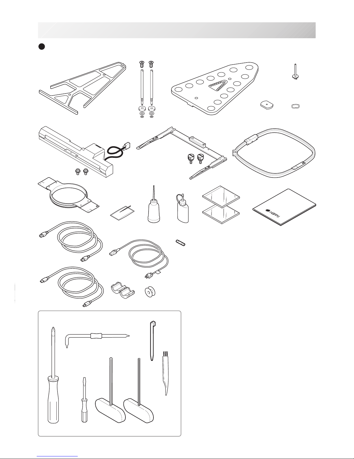
SETTING UPTHE MACHINE
Accessories
Please confirm you have received the following.
2_2 N909
2-2
1. Thread guide bracket
2. Thread guide pillar (2 pcs)
3. Thread stand
4. Thread stand felt (13 pcs)
5. Thread stand pin (13 pcs)
6. Wave washer (13 pcs)
7. Carriage
8. Frame base
9. Embroidery frame (square) PTA-32320-360
10. Embroidery frame (Round)
PTA-15-360
11. Needle (DB X K5) (10 pcs)
12. Oiler
13. Sewing machine oil
14. CD-ROM (Happy Link)
15. CD-ROM (Instruction manual, Parts list)
16. Instruction book (How to open the CD-ROM)
17. LAN cable
18. Power line cord ass'y (A shape will be changed
depending on a destination)
19. Fuse (6A)
20. Off set screw driver
21. #2 (+) Screw driver
22. 2 mm (-) Screw driver
23. 3 mm hexagonal driver
24. 2.5 mm hexagonal driver
25. Brush
26. Bobbin (1 pc)
27. Clamp filter
28. Stylus
29. USB cable
Tools
12463
789
11 12 13 15 16
20
21 22 23 24
5
25
14
28
29
17
10
27
3
26
-S2 -9
12
3
4
5
6
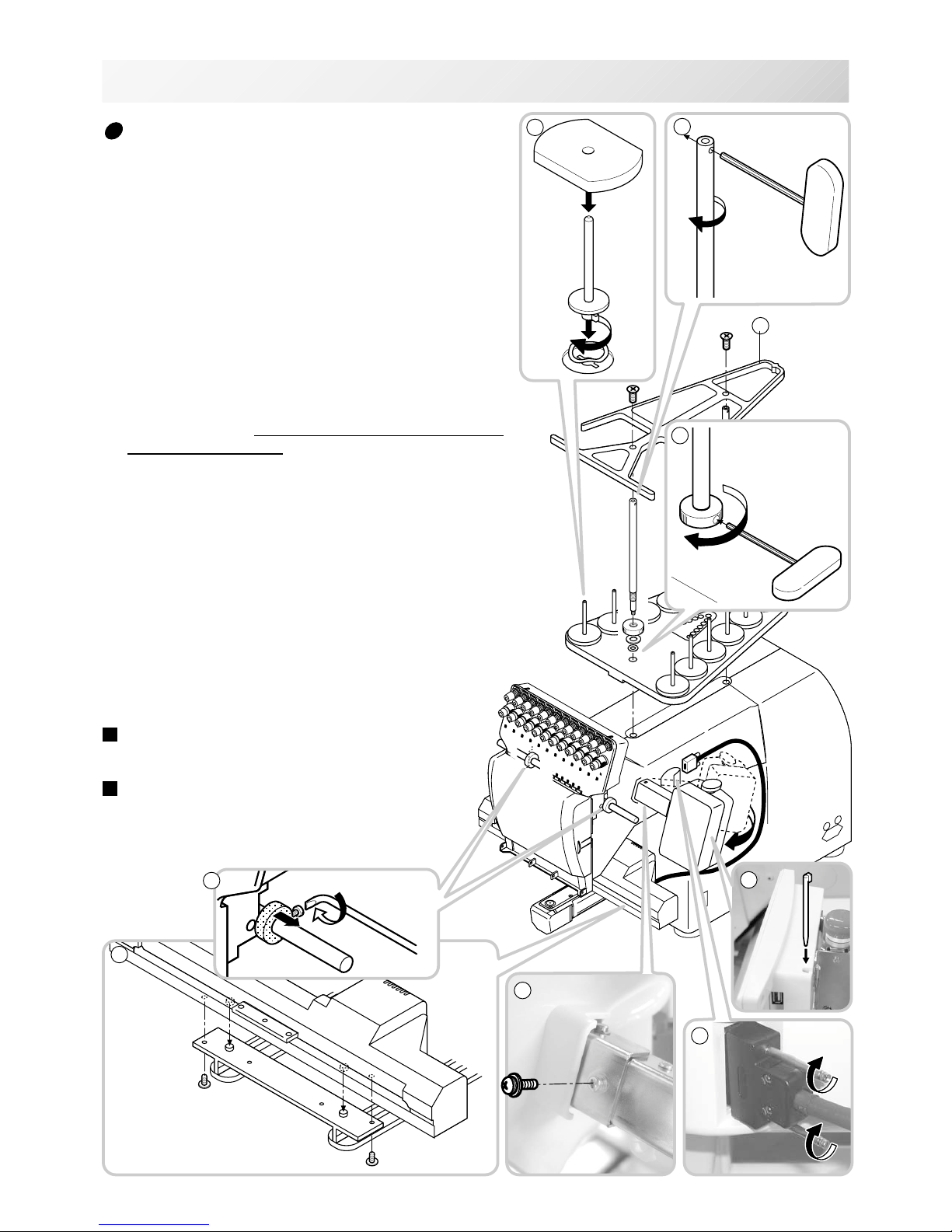
Assemble machine unit
1. Insert the thread stand pin with wave washer on the
thread stand by turning clockwise, Then insert thread
stand felt.
2. Put the thread stand on to the machine and insert the
thread guide pillar.
(set nut knob nut into the thread guide pillar and 2
washers)
Turn the thread guide pillar clockwise with a 3 mm
hexagonal driver until tight.
Turn the knob nut clockwise with a 3 mm hexagonal
driver until tight.
3. Install the thread guide bracket with supplied screws
(pan head screw M6 x 10 2 pcs).
4. Loosen the screw with a offset driver and remove the
red shipping collars that are equipped on the both side
of the guide bar. (Keep the shipping collars. It is nec-
essary when packing.)
5. Put the carriage and carriage arm together with screw
(M4 X 8 2 pcs).
2 pins in the upper carriage arm will fit into holes on
the lower carriage.
6. Raise slowly the control box to the front then fix it with
2 supplied screws (M4 1 pcs).
7. Connect the cable of carriage to the machine with
fixed screw.
8. Install the arm for tubular embroidery. Please refer to
(page 6-1) "Installing and removing the frame base".
Or, Install the cap frame for the cap embroidery.
Please refer to (page 7-1) "Installing and removing the
cap drive frame".
9. Insert built-in stylus into the holder (slot) of control
box.
When taking the machine apart in case of packing,
the process is opposite of assembling the machine.
Please do exactly the opposite way of assembling.
When packing the machine up for transportation,
be sure to select the sixth needle and fix it with
shipping collars on the both side of the guide bar.
2_3 N401
2-3
SETTING UPTHE MACHINE
7
2
9

-CS -7
Machine installation
1. Please use a stout table to set the machine
on.
Please check for any shaking or excessive vibrat-
ing of the machine table when the machine is
running.
If you have a problem, Please use a stronger
table for the machine.
2_4 D607
2-4
SETTING UPTHE MACHINE
350 mm 350 mm 720 mm
2. Please sit the machine level on the table.
3. Please be sure you have this much room
around your machine for it to move.
It is possible for the embroidery frame to hit you
and cause injury.
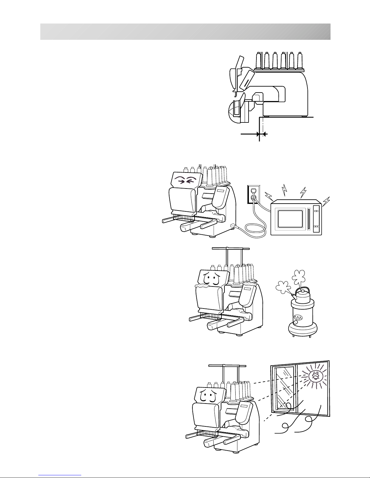
-CS -82_5 D607
2-5
SETTING UPTHE MACHINE
0 ~ 10 mm
4. Please be sure you have this much room around
your cap drive for it to move.
Please machine on the table positioning like right side
drawing.
5. Please do not sit the machine near any
kind of other electric equipment
(Examples: Microwave or electric tool).
Has possible to wrong movement of the
machine.
6. Please keep away from dusty and high mois-
ture environments.
Has case of rusting or damaging.
7. Please do not sit the machine in direct
sunshine or windy locations.
Has case of rusting or damaging.
-CS -11
Grounding instruction (for type of 120V)
This product must be grounded. In the event of malfunction or breakdown, grounding provides a
path of least resistance for electric current to reduce the risk of electric shock. This product is
equipped with a cord having an equipment-grounding conductor and a grounding plug. The plug
must be plugged into an appropriate outlet that is properly installed and grounded in accordance
with all local codes and ordinances.
DANGER – Improper connection of the equipment-grounding conductor can result in a
risk of electric shock. The conductor with insulation having an outer surface that is green with or
without yellow stripes is the equipment-grounding conductor. If repair or replacement of the cord
or plug is necessary, do not connect the equipment-grounding conductor to a live terminal.
Check with a qualified electrician or serviceman if the grounding instructions are not completely
understood, or if in doubt as to whether the product is properly grounded.
Do not modify the plug provided with the product – if it will not fit the outlet, have a proper outlet
installed by a qualified electrician.
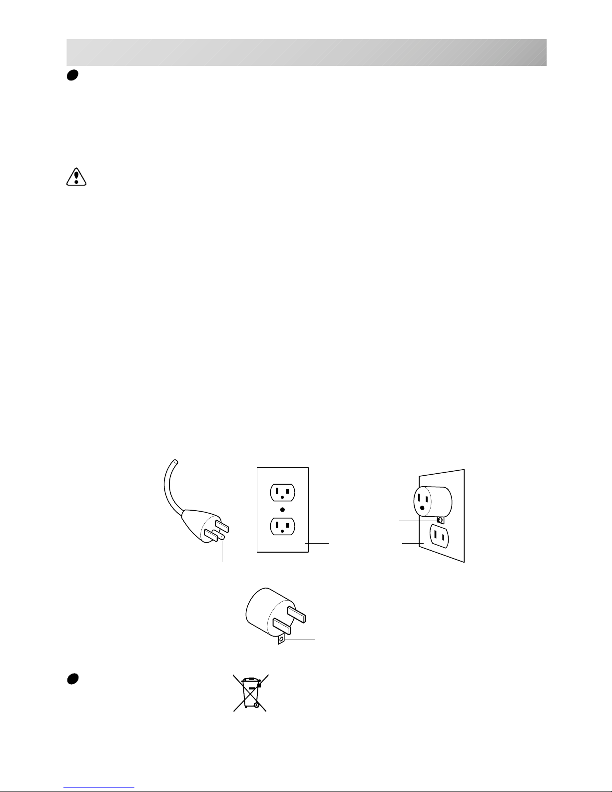
This product is for use on a nominal 120 V circuit, and has a grounding plug that looks like the
plug illustrated in sketch A in Figure. A temporary adaptor, which looks like the adaptor illus-
trated in sketches B and C, may be used to connect this plug to a 2-pole receptacle as shown in
sketch B if a properly grounded outlet is not available. The temporary adaptor should be used
only until a properly grounded outlet can be installed by a qualified electrician. The green col-
ored rigid ear, lug, and the like, extending from the adaptor must be connected to a permanent
ground such as a properly grounded outlet box cover. Whenever the adaptor is used, it must be
held in place by the metal screw.
2_6 I916
2-6
SETTING UP THE MACHINE
Disposal of a battery
A battery is had built-in to this embroidery machine.
When you dispose of a battery, according to each country or a method determined in each area,
please dispose appropriately.
Metal screw
Cover of grounded
outlet box
Grounding pin
Grounding means
Grounding methods
Adapter
AB
C

-S2 -10
MAIN PARTS
3_1 N909
3-1
1. Hook cover
2. Bobbin case
3. Hook
4. Needle plate
5. Thread check spring
6. Take-up lever cover
7. Take-up lever
8. Lower rectifier
9. Thread tension
10. Detecting roller
11. Minor thread tension
12. Thread guide support
13. Thread guide
14. Upper rectifier
15. Thread stand pin
16. Thread stand felt
17. Thread stand
18. Needle bar selection knob
19. Control box
20. USB port
(Standard-B receptacle)
21. USB port
(Standard-A receptacle)
22. LAN port
23. Frame base
24. Carriage
25. Fuse (6A)
26. Terminal box
27. Power switch
1
2
3
4
5
6
7
8
9
10
11
12
13
15
16
17
18
19
23
24
25
26
27
14
21
16
22
20

-S2 -113_2 M717
3-2
MAIN PARTS
BOBBIN WINDING
7
5
6
1
5
2
3
1. Upper Thread guide
2. Thread stand pin
3. Thread stand felt
4. Thread guide
5. Thread tension
6. Spindle
7. Lever
CONTROL BOX
45
1. Emergency stop button
2. Display (L.C.D.)
3. LAN port
4. Thread cut button
5. Start/Stop button
6
37
1
2
16
8
6. USB port (Standard-A receptacle)
7. USB port (Standard-B receptacle)
8. Stylus
-SA -12
HOWTO READ THESE INSTRUCTIONS and SCROLLBAR
3-3
3_3 NB01
The instructions in this manual have been formatted as follows:
Written instructions will be provided on the left side of the page while graphics depicting the
necessary steps are provided on the right.
Graphics on the far right will show the display after performing the steps indicated.
This indicates an additional
explanation on an operation
elsewhere in the manual for
more detail.
AWords marked with a "*" are explained in
"EMBROIDERY TERMS" at the end of this
instruction manual.
CAUTION: To prevent accidents.
This will appear for items related to your safety.
CAUTION: To avoid problems.
This will appear for items related to potential problems.
Order of operation
Indicates supplementary
explanation regarding a
given operation or action.
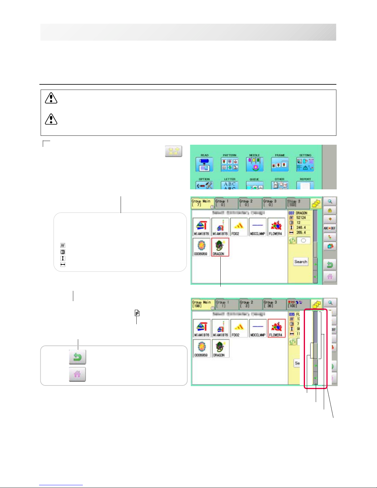
1. When the machine is stopped, press .
2. Select "PATTERN".
The display indicates the current pattern.
The left side of display shows the number, name
and details for the current pattern.
Number of stitches
Number of Color change number
Height
Width
3. Select *pattern data.
This pattern will be selected.
3-3
Selected pattern data
Operation key
Press to return to Menu mode.
Press to return to Drive mode.
Scrollbar
Display area
Scroll area
Arrow key
Scrollbar
If the data are too much to fit into display screen, you can use scrollbar.
Display area : It shows the area which is displayed.
Arrow key : You can scroll the display area to arrow marked direction.
Scroll area : It shows the whole area of the data.
You can push arbitrary point of Scroll area to display the desired location.
-SA -16
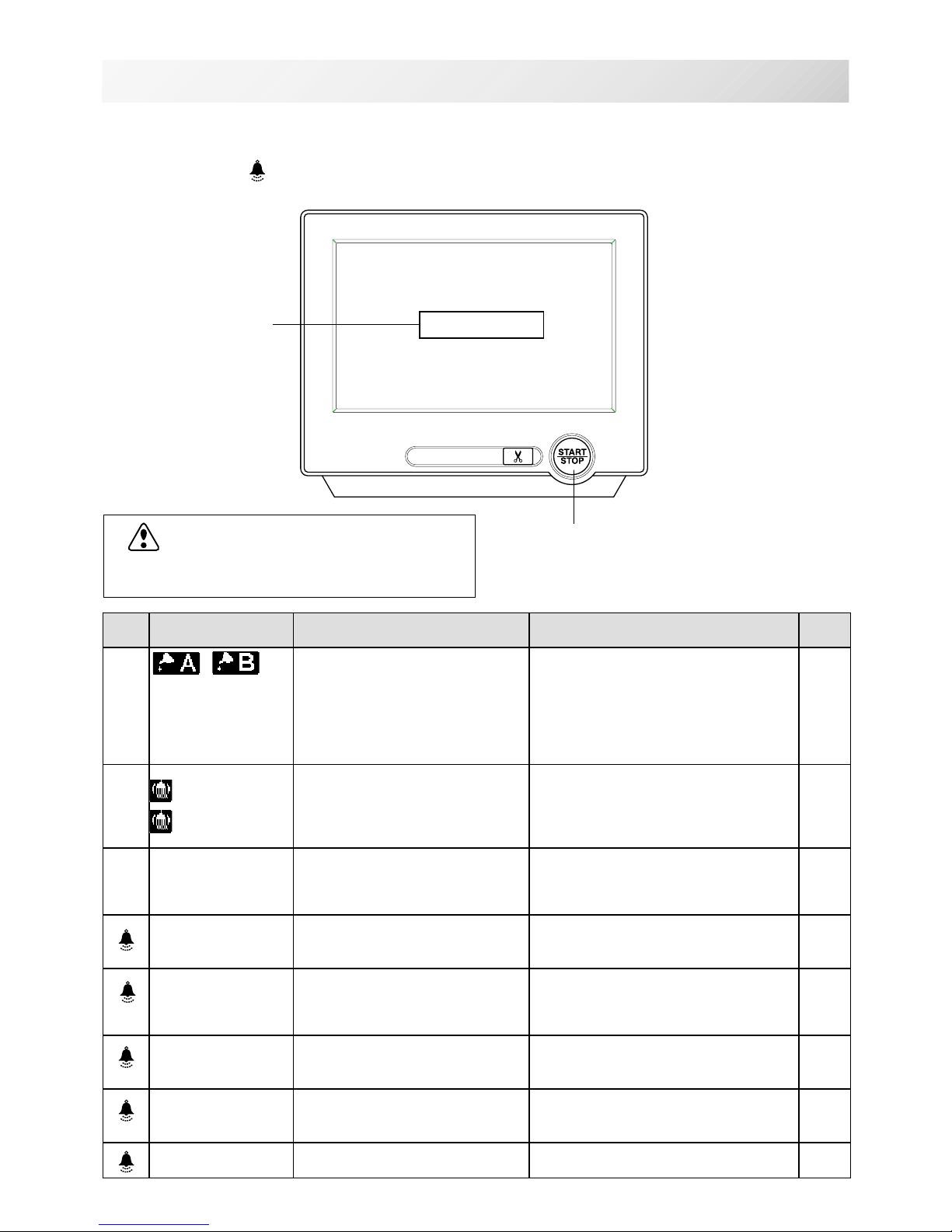
MESSAGES 3-4
3_4 O512
Below is a list of possible messages that may appear while operating the machine, along with
an brief explanation and suggested actions to take as a result.
The message with mark will be appeared with beep sound.
Press the screen (any location is okay), then message will disappear.
Start/Stop button
Message
>>Stop Switch
CAUTION: To prevent accidents.
The embroidery frame may move. Please
keep hands clear for your safety.
MESSAGE EXPLANATION OPERATION PAGE
Place to oil
Designated letter on the display
is due to be lubricated. Push [Done] and lubricate indicated
location with instruction in
the reference page.
Push [Leter], if you can not lubricate
right away.
The message will be disappeared
temporary, but it will come up later.
23-1
Cleaning of
rotary fook
Cleaning of
thread cut
knife
Clean the rotary hook and the
thread cutting knife. Clean with instruction in the
reference page. 23-2
>>Stop Switch The machine is stopped
because the stop button was
pressed while embroidering the
design.
Press the start/stop button to resume
sewing.
>>End The machine is stopped
because it has finished the
design.
If you wish to sew design again,
please newly hooped item on
machine & press start/stop button.
>>Change Stop Machine stopped, because you
used "Stop at color change
point" function.
When you press the start/stop button,
the machine will select the next color
and resume embroidering
automatically.
>>Color ? Machine stopped because the
next color has not been
selected.
Please select next needle number by
needle selection button then press
the start/stop button.
>>Thread Break Machine stopped, because
upper or bobbin thread broken. Please thread upper thread or check
bobbin thread then press start/stop
button to resume sewing.
>>Frame out The "Frame out" function has
been executed. Press the start/stop button if OK.
12-D

-SA -14
TURNINGTHE MACHINE ON
1. Connect the power cord to the inlet on the
right side of the machine.
2. Connect the power plug to an electrical
outlet.
3. Turn on the power switch.
Please confirm the emergency stop button has
been released.
Push the power switch firmly so it will remain on.
4. In case you do not need to change frame
type, Press .
After the carriage and frame move slightly, the
embroidery frame will return to the previous
position automatically.
Machine becomes ready for operation.
3_5 NB25
3-5
ON
OFF
Power switch
CAUTION: To prevent accidents.
The embroidery frame and carriage will move.
Please keep hands clear for your safety.
Selected frame
In case you want to change frame type,
Press .
CAUTION
The touch screen can be operated by finger,
but in some cases sensitivity of the screen will
be affected by condition of the finger.
In such cases, please use the fingertip or
built-in stylus to hit small touch targets.
How to turn on the machine
-D2 -18
TURNINGTHE MACHINE ON
3_6 N101
3-6
DANGER: To reduce the risk of electric shock.
Never leave the machine unattended when plugged in.
Always unplug this machine from the electrical outlet immediately after use and before per-
forming any maintenance on it.
WARNING: To reduce the risk of burns, fire, electric shock, or injury to persons.
Do not unplug by pulling on cord. To unplug, grasp the plug, not the cord.
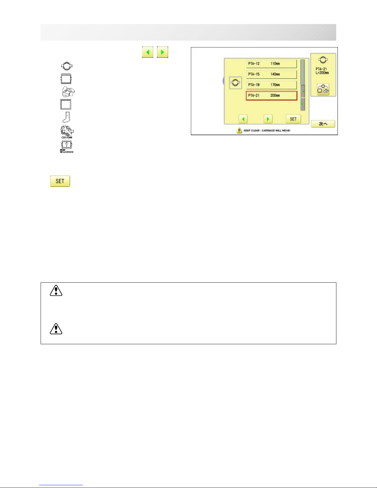
5. Select the desired frame with .
: Tubular round frame
: Tubular square frame
: Cap and One-point frame.
: Border frame (for HCD2)
: Sock frame
: User-defined frame
: Non registered
6. Select desired type of frame and Press
.
The display returns to the view of Step 3.
To disconnect, switch the power switch to the
off position, then remove plug from outlet.
-D2 -19
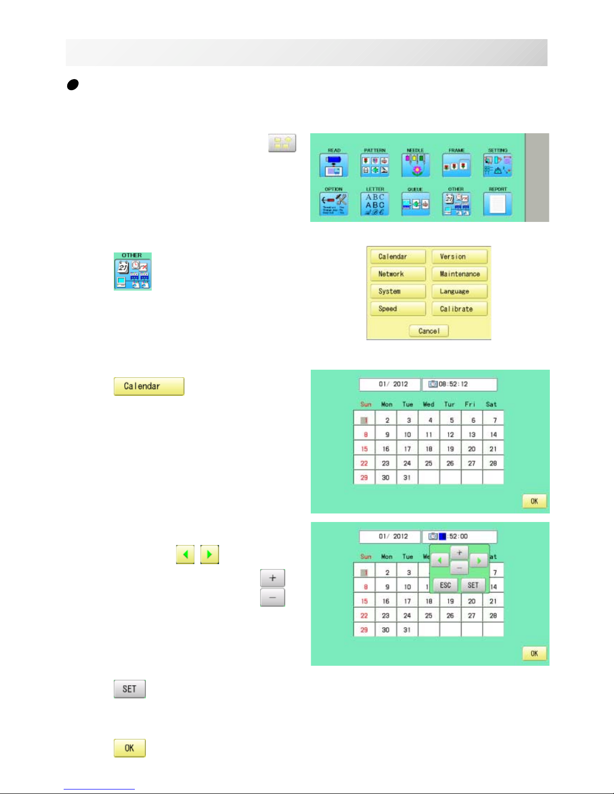
1. When the machine is stopped, press .
2. Press .
3. Press .
Current year, month date and time is displayed.
4. Select year/month, time or date.
Press right /left of to select the
setting point, and press up/down of to
select the number of year, month and time.
5. Press .
The date is fixed.
6. Press to return to Menu mode.
Calendar and clock setting
Setting the calendar and clock lets the machine advise when oiling and other maintenance is
scheduled to occur.
TURNINGTHE MACHINE ON 3-7
3_6 M620
Other manuals for HCS2
1
Table of contents
Other Happy Industrial Corporation Sewing Machine manuals

Happy Industrial Corporation
Happy Industrial Corporation HCS2 User manual

Happy Industrial Corporation
Happy Industrial Corporation HCR Series User manual

Happy Industrial Corporation
Happy Industrial Corporation HCD2 User manual

Happy Industrial Corporation
Happy Industrial Corporation HCS User manual

Happy Industrial Corporation
Happy Industrial Corporation HCD User manual

Happy Industrial Corporation
Happy Industrial Corporation C User manual


