Happy HK634020XB User manual

Maintenance Manual for Embroidery Machine
(Color Display Additional Manual)
HCS-1201-30
Version 1.0
HAPPY Industrial Corporation

2
# For safe adjustment and repair #
In order to conduct adjustment and repair safely and surely,
please be sure to abide by what is mentioned in this manual to prevent trouble.
1. When you conduct adjustment and repair of this embroidery machine or handle electric related parts,
you are required to take technical lesson in advance.
2. When you conduct adjustment and repair using this manual, please be sure to use together with instruction
with it in hand.
# Please conduct in accordance with work process in this manual.
# In case there are no specific instructions or explanations in work process.
please be sure to unplug cord from receptacle.
# When you exchange parts, please be sure to use genuine parts designated by us.
# Please never remodel the embroidery machine.
When you handle circuit boards:
# In order to prevent troubles from static electricity, please remove earth from human body.
# Please don't touch metal part of circuit board with bare hand as it will short-circuit
and threaten to break circuit boards.
# When you removed circuits boards from the machine or you store or transport them,
please wrap them in static electricity preventive bag and avoid to give shock.

3
Index
page
cover 1
For safe adjustment and repair 2
Index 3
1 Parts Replacement in control panel and setting 4
1-1 Open and remove front panel from control box
1-1-1 Open the front panel on the control box 5
1-1-2 Remove ATA LCD board 6
1-2 Dip switch setting for ATA LCD board 7
2 Initialization of system 8
2-1 Notice for update and Initialize machine systems 9
2-2 Operation order for update and Initialize machine systems. 10
2-3 Detail operation order for update machine systems
2-3-1 How to Update Program for Control of ATA LCD Board. 11
2-3-2 How to Change Language Setting. 12
2-3-3 How to Update CPU Board Program (from EP-ROM) 13
2-3-4 How to Update CPU Board Program (from CF card) 14
2-3-5 How to Update Internal Monogramming Data 15
2-4 Initialization of memory
2-4-1 Initialization ATA LCD board memory 16
2-4-2 Initialization CPU board memory 16
2-5 Setting of Revolution 17
2-6 Setting to detect needle position (for 12 needles). 18.19
3 Maintenance mode. 20
3-1 How to enter maintenance mode 21
3-2 Machine Machine movement 22
3-3 Memory Memory (Machine and Design) check and all erase. 23
3-4 Record Opereration data display
3-4-1 Thread Pattern Number of thread brake times in relation to pattern data 24
3-4-2 Thread Needle Accumulated total of thread break of a needle 25
3-4-3 Error Error occurred and the accrual date 26
3-5 Setup Machine setting. 27
4 Electric system diagram(Color Display) 28
4-1 Electrical connection diagram. 29
4-2 List of electrical connection diagrams 30

4
1 Parts Replacement in control panel and setting
1-1 Open and remove front panel from control box
1-1-1 Open the front panel on the control box
1-1-2 Remove ATA LCD board
1-2 Dip switch setting for ATA LCD board

5
Open and remove front panel from control box 1-1
Open the front panel on the control box 1-1-1
<Check> Please check down machine power completely.
1. Remove four setscrews behind of control panel
2. Open control panel like following picture.
(Open the cover from right side)
<Note>
Please do not wide open on the left side.
(Possible, make damage to wiring cable and electric board)
Please do not turn on power when inverter cover (refer to
the bellow), otherwise the machine might be damaged.
3. Disconnect Inverter power cable.
4. Disconnect for LCD-SW cable
5. Disconnect LCD-S cable.
1. Pull stopper on CN7 (ATA LCD Board)
2. Pull out the LCD-S cable.
Finish of procedures
For assemble and close this panel: Please opposite steps of
this procedure.
4 set screws
Closing the left side
Inverter cover
Inverter power cable
LCD-SW cable
1
2
Stopper
LCD-S cable

6
Open and remove front panel from control box 1-1
Remove ATA LCD board 1-1-2
1. Disconnect emergency SW cable
2. Disconnect DISP cable. (Please off stopper first)
3. Remove ATA LCD board
Remove four setscrews
Finish of procedures
Emergency SW cable
CN1
DISP cable
Four setscrews

7
Dip switch setting for ATA LCD board 1-2
1 ------ON Initialize back up data
OFF. Non Initialize(Regular)
2 ------OFF. Regular
3 ------OFF. Regular
4 ------ON
5 ------ON
6 ------OFF.
7 ------OFF.
8 ------OFF.
9 -----OFF. Regular
10 ---OFF. Regular
Color LCD Size
External
Regular
Regular
Detail of External switch (Normally, dose not use at maintenance)
7 8
ON ON Forbid
ON OFF Erase of language data.
OFF ON Forbid
OFF OFF Normal machine work(Regular)

8
2 Initialization of system
2-1 Notice for update and Initialize machine systems
2-2 Operation order for update and Initialize machine systems
2-3 Detail operation order for update machine systems
2-3-1 How to Update Program for Control of ATA LCD Board
2-3-2 How to Change Language Setting
2-3-3 How to Update CPU Board Program (from EP-ROM)
2-3-4 How to Update CPU Board Program (from CF card)
2-3-5 How to Update Internal Monogramming Data
2-4 Initialization of memory
2-4-1 Initialization ATA LCD board memory
2-4-2 Initialization CPU board memory
2-5 Setting of Revolution
2-6 Setting to detect needle position (for 12 needles)

9
Notice for update and Initialize machine systems 2-1
* Please install program when update (Machine system program, Internal Monogram data) and Replace circuit board (CPU board,
ATA LCD board) and indication language.
* Contents of system program for HCD are as follows:
CPU Board
OS. : HCS/H **** (program for control of CPU board )
Letter : LTR*** (Internal Monogramming data)
LCD Board
Control. : LCDH**** (program for control of LCD board )
Language. : H_ENG*** (English)
: H_JPN*** (Japanese)
* System program above will be shown as below on PC screen
Program for control of CPU board : HCS/H ****----------------->.CHCS***.bin
Internal Monogramming data : LTR***----------------------->.LTR***.bin
Program for control of LCD board : LCDHA***------------------> LCDHA***.upi + LCDHA***.bin : 2 files required
Language (English and others) : H_ENG***------------------> H_ENG***.upi + H_ENG***.bin : 2 files required
<NOTE>
Pleasedo not write system program in folder in CF card when you upgrade machine by writing system program in CF card by
PC as machine becomes unable to recognize version up program (please write system program on route of subject media).
* In case, upgrade plural programs same time, please keep following priority install order.
1:LCDH****( program for control of LCD board )
2:H_ENG*** or H_JPN*** (language)
3:HCS/H ****( program for control of CPU board )
4:LTR***( Internal Monogramming data)
<NOTE>
* After replace board and upgrade program, please operate following items.
1. After upgrade LCD board program (Control and Language), please operate chapter [2-4-1 Initialization ATA LCD board
memory LCD] for clear a memory.
2. After update CPU board program (OS and Letter), please reference following chapters for set Memory clear, set machine
speed, needle position, system initialize and calendar set.
1: [2-4-2 Initialization CPU board memory ]
2: [2-5 Setting of Revolution]
3: [2-6 Setting to detect needle position (for 12 needles)]
4: [3-3 memory (Machine and Design) check and all erase]
5: In an Instruction book [25-1.2 Initialize machine] and [3-7 Calendar setting]
3. You can install and update all program from CF card.
But, in case of you have problem of electricity whole program install, possible loose CPU operation program completely. In this
time you need install CPU operation program from EP-ROM tip only.

10
Operation order for update and Initialize machine systems 2-2
* Work sequence of Updating Program are described below.
If you need more detail information fro each sequence, please reference each manual
1. Insert CF card saved update program to slot of control panel.
Press and keep [MENU] button and turn on the machine
2. Go to maintenance mode and practice install.
3. Update [CPU board program] from EP-ROM tip.
(In case, Machine program brake completely, you can re-install CPU board program
only from EP-ROM tip)
Turn off machine and connect EP-ROM saved machine program tip to socket on CPU board.
Flip dipswitch [DSW2 to OFF] and [DSW4 to ON], then turn on machine.
Start copy of CPU board program automatically.
After a copy, Please turn off machine power and flip back dipswitch [DSW2 to ON] and
[DSW4 to OFF].
4. [Update LCD board control program]
Flip dipswitch [DSW1 to ON] on ATA LCD board. And turn on machine.
Starts initialize
5. [Update LCD board control program]
Turn off machine power And Flip back dipswitch {DSW1 to OFF}.
6. Flip dipswitch [DSW1 to OFF] on CPU board. And turn on machine.
Starts initialize memory.
7. Turn off machine and flip back dipswitch [DSW1 to ON] on CPU board.
Press and keep [MENU] button and turn on machine power.
8. Memory checks at maintenance mode.
9. Re-turn on the machine
Come up [E-120] on display, and press [SET] button for turn off machine power.
10. Press and keep [MENU] button and turn on machine power.
11. Needle setting at maintenance mode.
(”D”for 1st needle ,”E”for 12th needle ,”F”for check)
12. Exit maintenance mode.( Press [ESC] button for back to drive mode)
Check moving head working correctly.
13. Initialize machine system
14. Machine speed teaching
15.Calender setting
16.end of process
2-4
Initialize memory
2-6
Needle position setting
Instruction book
25-1.2 Initialize machine
Instruction book
3-7 Calendar setting
3-3
Check and all clear a
memory
2-3
UPDATE PROGRAM

11
How to Update Program for Control of ATA LCD Board 2-3-1
1. Update of ATA LCD board program
Insert CF card contains data for version up into CF card
insertion slot
2. .Refer to “3-1 How to enter maintenance mode”and enter
maintenance mode. Display comes as below.
3. Place cursor at [ Install ] by button and press SET
button.
4. Showing menu on right side of screen.
Select [ install ] by button and press SET button.
5. Display comes as below after reading data in CF card
6. Press SET button for update of ATA LCD board program
<NOTE>
* Please do not take out CF card during installation.
* Will show following message
* For cancel, press ESC button and back to last menu
7. Completely, and re-boot machine.
If you have [ Error ] message, please operate from step 1 of
this process again.
* End of process
[Maintenance]
> Machine : A
Angle. : 0
Memory. :
Display : 1
Install. :
Record :
[Maintenance]
Machine : A
Angle. : 0
Memory. :
Display : 1
> Install :
Record :
[Maintenance]
Machine : A
Angle : 0
Memory .:
Display : 1
>. Install :
Record :
> install
prog
lettr font
[Maintenance]
[ Install mode ]
> 1 : LCD/H **.**
LCD Control Program Installing

12
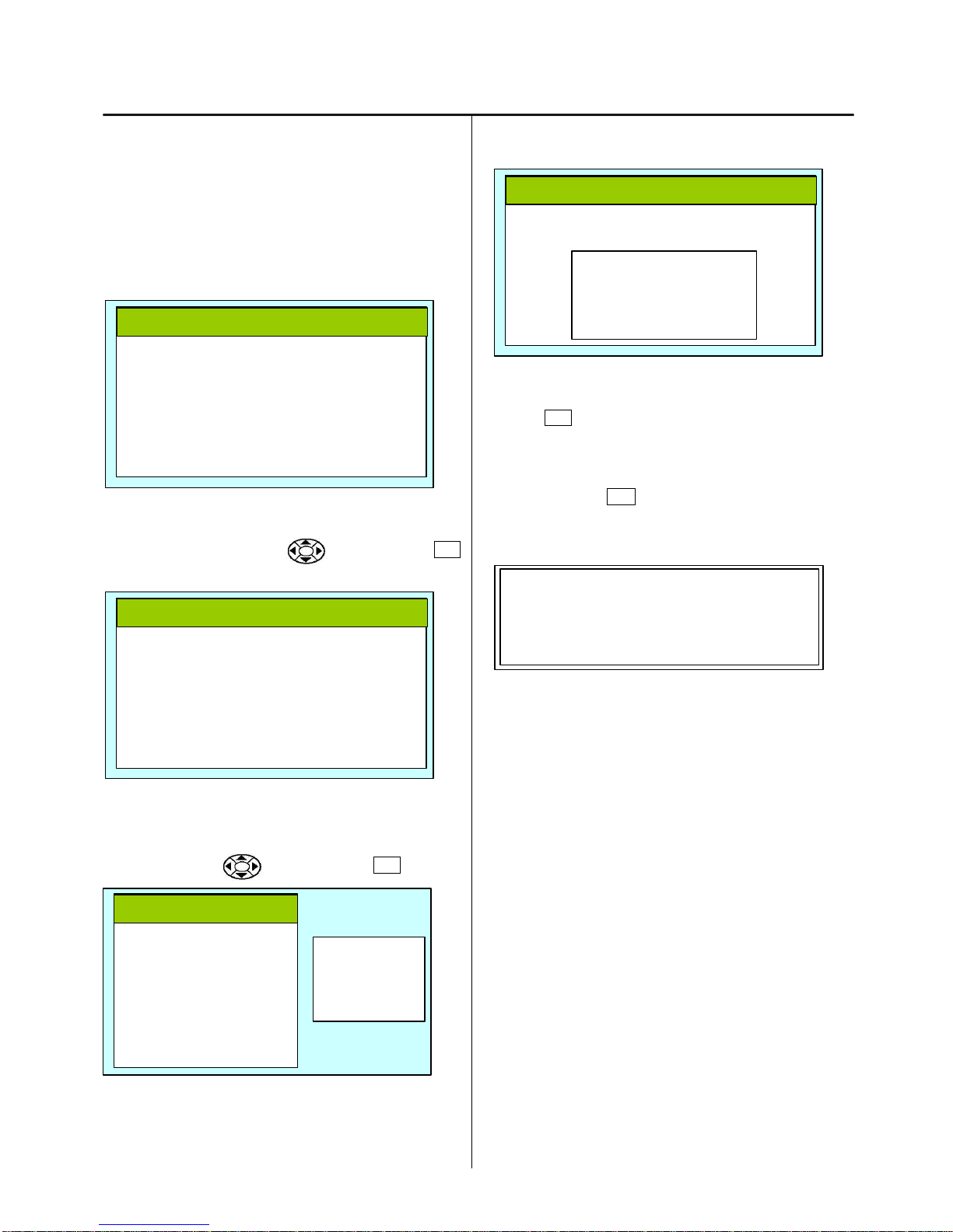
How to Change Language Setting 2-3-2
1. Change language of LCD panel
Insert CF card included language data to card slot of
control panel. Refer to “3-1 How to enter maintenance
mode”and enter maintenance mode. Display comes as
below.
2. Set cursor at [ Install ] by button and press SET
button.
3. Will show the menu on right side.
Set cursor at [ install ] by button and press SET
button.
4. Display comes as below after reading data in CF card
5. Select your language and press SET button. Start install
automatically.
* File name of language
English H_ENG***
Japanese H_JPN***
German H_GER***
Danish H_DAN***
<NOTE>
* Please do not take out CF card during installation.
For cancel, press ESC button and back to last menu.
6. Indicate [ complete ], then return to drive menu
automatically.
Please retry when you have display as “Error ”by mistake
of writing.
* end of process
[Maintenance]
Machine : A
Angle : 0
Memory :
Display : 1
> Install :
Record :
[Maintenance]
Machine : A
Angle : 0
Memory :
Display : 1
> Install :
Record :
> install
prog
lettr font
[Maintenance]
[ Install mode ]
> 1 : H_ENG***
2 : H_JPN***
[Maintenance]
[ Install mode ]
- - - - - Installing Data - - - -
[Maintenance]
[ Install mode ]
- - - - - Complete - - - -

13
How to Update CPU Board Program (from EP-ROM) 2-3-3
1. Update of CPU board program
Insert ROM in socket with power off
Control-program
[HCS/H **.**]
Dented side on the bottom.
2. Set No.4 of [DS1] to [ON] and No.2 to [OFF] to
turn power on.
Indicating process
3. Display [complete]
When you make wrong writing, message of "error" will be
displayed. Please write again
<Judgment by circuit board itself>
Lighting condition of LED4 on the CPU Board enables you to
distinguish the result.
Normal complete : 8times blinking --- lighting
Writing error : 8times blinking --- blinking
Retry if writing error occurs.
4. Turn power off and set No.4 of DS1 to OFF, No.2 to ON.
5. Remove ROM.
* End of process
HCS/H
A*.**
Load 2.01
[> > > > ]
Load 2.01
- - - - - > Complete
14
How to Update CPU Board Program (from CF card) 2-3-4
1. Update of CPU board program
Insert CF card contains data for version up into CF card
insertion slot
2. Refer to “3-1 How to enter maintenance mode”and enter
maintenance mode. Display comes as below.
3. Place cursor at [Install] by button and press SET
button.
4. Display menu on right side below.
Select [ prog ] by button and press SET button.
5. .Display comes as below after reading data in CF card
6. Press SET for start program update
<NOTE>
* Please do not take out CF card during installation.
* For cancel, press ESC button and back to last menu.
* Display comes as below.
12. When completed, reboot machine automatically
Please retry when you have display as “Error”by mistake
of writing.
* End of process.
[Maintenance]
> Machine : A
Angle. : 0
Memory. :
Display : 1
Install. :
Record :
[Maintenance]
Machine : A
Angle. : 0
Memory. :
Display. : 1
> Install. :
Record. :
[Maintenance]
Machine : A
Angle. : 0
Memory. :
Display : 1
> Install. :
Record :
install
>. prog
lettr font
[Maintenance]
[ Program install ]
> 1 : CHCSA***
Load 2.01
- - - - - > Complete

15
How to Update Internal Monogramming Data 2-3-5
1. Update for Internal Monogram data.
Insert CF card saved update data. Refer to “3-1 How to
enter maintenance mode”and enter maintenance mode.
Display comes as below.
2. Place cursor at [ Install ] by button and press SET
button.
3. Showing menu on right side of screen
Select [ letter font ] by button and press SET button.
4. Display comes as below after reading data in CF card
5. Press SET button for start update of monogram data.
<NOTE>
Please do not take out CF card during installation
For cancel, press ESC button and back to last menu.
6. When completed, comes as below display [ complete] and
reboot machine automatically.
Please retry when you have display as “Error”by mistake of
writing.
* End of process
[Maintenance]
Machine : A
Angle. : 0
Memory. :
Display : 1
> Install :
Record :
[Maintenance]
Machine : A
Angle. : 0
Memory. :
Display : 1
> Install. :
Record :
install
prog
>. lettr font
[Maintenance]
[ Lettr install ]
> 1 : LTR * * *
Write 1.01[ * * * * ]
- - - - - > Complete

16
Initialization of memory 2-4
At time of start-up, this is to initialize work memory to specified value. Initialization takes place
Initialize “work memory”. Please practice when you have problem example, strange display, strange machine working. After
initialize “working memory”, Please set machine speed and needle position setting.
Initialization ATA LCD board memory 2-4-1
1. Please flip dipswitch DS1-1 on ATA LCD board. Then turn on the machine
2. End of initialize. Please turn off machine and flip back dipswitch DS1-1 to [OFF].
Initialization CPU board memory 2-4-2
1. Set DS1-1 on CPU board to [OFF] to turn power on.
2. You will have no problem in starting and finishing initialization. Please turn power off to set DS1-1 to ON after initialization
3. Please set as refer following process.
1. [2-5 Setting of Revolution]
2. [2-6 Setting to detect needle position (for 12 needles)]
3. Instruction book [25-1.2 Initialize machine] and [3-7 calendar setting]
<NOTE>
You are unable clear pattern memory area. If you want to clear, Please refer to [3-3 memory (Machine and Design) check and all
erase ].
DS1-1
DS1-1

17
Setting of Revolution 2-5
Setting of revolution of main shaft, which is suitable to the
machine is required.
If setting is not done, the revolution may not speed up.
1. Turn on the power. After the program start up, press MENU
button.
2. Press to select OTHER window and press SET
button.
Displayed as bellow.
3. Press to select Speed and press SET button.
Press to select [OK] and press SET button.
5. Main shaft adjusts its revolution speed automatically.
Message complete will be displayed when setting is
finished and it goes back to drive mode.
End of process.
Speed setting OK?
CAUTION! <Main shaft turns>
Cancel
OK
- - - Complete - - -

18
Setting to detect needle position (for 12 needles) 2-6
It is necessary to store value of needle selection sensor
according to number of needles. If this setting is not made,
normal needle selection may not be made.
1. Sift moving head to first needle by hand turning knob
2. Refer to “3-1 How to enter maintenance mode”and enter
maintenance mode.
3. Place cursor at [ machine ] by button and press
SET button
4. Press button and select “D ”then press SET
button. Memory first needle position to machine.
<Check>
When you press SET button, comes up “# ”mark split
second for proof memory needle position to machine
completely.
5. Slide moving head to 12th needle by hand.
[Maintenance]
> Machine : A
Angle. : 0
Memory. :
Display : 1
Install. :
Record :
[Maintenance]
> Machine : #D
Angle. : 0
Memory. :
Display : 1
Install. :
Record. :

19
Setting to detect needle position (for 12 needles) 2-6
6 Press button and select “E ”then press SET
button. Memory 12th needle position to machine.
<Check>
When you press SET button, comes up “# ”mark split
second for proof memory needle position to machine
completely.
7. Press button and select “F ”then press SET
button.
8. Right side of [ : F ] Indicate present needle number on
display.
Please slide moving head by hand and confirm 1 to 12 all
needle displayed number and present needle number
9. Press SET button for return to top menu of maintenance
mode.
10. Press ESC button for back to drive mode.
End of process
[Maintenance]
> Machine : #E
Angle. : 0
Memory. :
Display : 1
Install. :
Record. :
[Maintenance]
> Machine : F
Angle. : 0
Memory. :
Display : 1
Install. :
Record. :
[Maintenance]
> Machine : #F 12
Angle. : 0
Memory. :
Display : 1
Install. :
Record. :
[Maintenance]
> Machine : F
Angle. : 0
Memory. :
Display : 1
Install. :
Record. :

20
3 Maintenance mode
3-1 How to enter Maintenance mode
3-2 Machine Machine movement
3-3 Memory Memory (Machine and Design) check and all erase
3-4 Record Opereration data display
3-4-1 Thread Pattern Number of thread brake times in relation to pattern data
3-4-2 Thread Needle Accumulated total of thread break of a needle
3-4-3 Error Error occurred and the accrual date
3-5 Setup Machine setting
This manual suits for next models
1
Table of contents
Other Happy Sewing Machine manuals

Happy
Happy HCS2-1201 Troubleshooting guide

Happy
Happy HCS-1201-30 User manual

Happy
Happy HCS2-1201-30 User manual

Happy
Happy HCH-701 User manual

Happy
Happy HCG Series User manual

Happy
Happy HCH User manual

Happy
Happy HCH User manual

Happy
Happy HCD Instruction sheet

Happy
Happy HCD-1501 Installation guide

Happy
Happy HCH Series User manual


