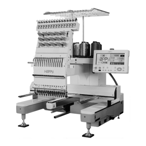
Happy HCS-1201-30 User manual

Maintenance Manual for Embroidery Machine
HCS-1201-30
Version 3.0
HAPPY Industrial Corporation

2/204
# For safe adjustment and repair #
In order to conduct adjustment and repair safely and surely,
please be sure to abide by what is mentioned in this manual to prevent trouble.
1. When you conduct adjustment and repair of this embroidery machine or handle electric related parts,
you are required to take technical lesson in advance.
2. When you conduct adjustment and repair using this manual, please be sure to use together with instruction
with it in hand.
# Please conduct in accordance with work process in this manual.
# In case there are no specific instructions or explanations in work process.
please be sure to unplug cord from receptacle.
# When you exchange parts, please be sure to use genuine parts designated by us.
# Please never remodel the embroidery machine.
When you handle circuit boards:
# In order to prevent troubles from static electricity, please remove earth from human body.
# Please don't touch metal part of circuit board with bare hand as it will short-circuit
and threaten to break circuit boards.
# When you removed circuits boards from the machine or you store or transport them,
please wrap them in static electricity preventive bag and avoid to give shock.

3/204
Index
page
cover 1
Forsafeadjustmentandrepair 2
Index 3,4,5,6,7
1Outlineofmechanism 8
1-1Outlineofmechanicalmechanism 9,10
1-2 Placement of key electronic parts 11
2Outercovers 12
2-1Removalofoutercovers 13,14,15,16
3Mechanicalmechanism 17
3-1Basicmaintenance 18
3-1-1 Maintenance of thread path 19,20
3-1-2 Fixing of needle 21
3-1-3 Selection of thread 22
3-1-4 Relation between needle and upper thread 23
3-2Fixedhead 24
3-2-1 Exchange of crank 25,26,27,28
3-2-2 Exchange of rod 29,30
3-2-3 Adjustment of the lowest needle point 31
3-2-4 Exchange of needle bar driver 32,33
3-2-5 Adjustment of fixing of jump solenoid 34,35
3-2-6 Exchange of take-up lever cam 36,37
3-2-7 Exchange of roller shaft ass’y 38
3-2-8 Adjustmentoftake-uplevertiming 39
3-2-9 Exchange of pressure foot cam 40
3-2-10 Check of height of pressure foot 41
3-2-11 Exchange of pressure foot 42
3-2-12 Adjustment of height of pressure foot guide bar 43
3-2-13 Exchange of pressure foot link and block 44
3-2-14 Exchange of pressure foot drive lever 45,46,47
3-2-15 Exchange of pressure foot guide 48,49
3-2-16 Exchange of pulse motor for pressurefoot 50,51
3-2-17 Adjustment of pressure foot bracket ass’y 52
3-2-18 Exchange of thread catcher 53

4/204
Index
page
3-2-19 Exchange of thread catcher guide 54
3-2-20 Disassembling and Cleaning of jump solenoid 55
3-2-21 Adjustment of bobbin winder 56,57
3-3 Moving head 58
3-3-1 Assemblethe
upper rail of movinghead 59
3-3-2 Adjustment of backlash (back and forth) of moving head 60
3-3-3 Assemblethe
moving head 61,62,63,64
3-3-4 Adjustment of needle position (back and forth) 65
3-3-5 Check of needle position 66
3-3-6 Adjustment of needle height 67,68
3-3-7 Exchange of needle bar, needle bar spring and cushion 69,70
3-3-8 Fixing of needle bar boss guide plate 71
3-3-9 Exchange of take-up lever 72,73
3-3-10 Exchange of thread adjusting spring 74,75
3-3-11 Adjustment of tension of thread adjusting spring 76
3-3-12 Adjustment of stroke of thread adjusting spring 77
3-3-13 Adjustment of thread holder 78,79
3-3-14Exchangeofmajic-tapeonthreadholder 80
3-4Needlebarchangeunit 81
3-4-1 Fixing of needle bar change unit 82
3-5 Rotary hook 83
3-5-1 Adjustment of rotary hook timing 84,85
3-5-2 Adjustmentofretaineronrotaryhook 86

5/204
Index
page
3-6 Thread cut unit 87
3-6-1 Assemblethearmass’y 88,89
3-6-2 Exchange of thread cutting roller 90,91,92
3-6-3 Adjustmentofspacerass’y 93
3-6-4 Adjustment of thread cutting stopper 94
3-6-5 Adjustment of thread cut timing 95,96
3-6-6 Exchange of moving knife 97
3-6-7 Exchange of fixed knife 98
3-6-8 Adjustment of moving knife and fixed knife 99
3-6-9 Adjustment of position of moving knife 100
3-6-10 Adjustment of bobbin thread holder 101
3-6-11 Exchange of keeper solenoid 102
3-6-12 Adjustment of position of keeper 103
3-7 Carriage unit 104
3-7-1 Adjustment of X carriage belt tension 105,106
3-7-2 Exchange of X carriage belt 107-109
3-7-3 AdjustmentofYcarriagebelttension 110-112
3-7-4 Exchange of Y carriage belt 113-115
3-8Transmissionunit 116
3-8-1 Adjustmentoftimingbelttension 117
3-8-2 Exchange of timing belt 118,119
3-8-3 Adjustmentofmotorbelttension 120,121
3-8-4 Exchange of motor belt 122,123
4Electricity 124
4-1Circuitboardrelatedparts 125
4-1-1 Setting of dip switch for CPU board 126
4-1-2 Exchange of battery 126
4-1-3 Setting to fix power supply 127
4-2Sensors 128
4-2-1 Adjustment of upper shaft timing (C point / L point) 129
4-2-2 Adjustment of TC board 130
4-2-3 Adjustment of stop position of needle bar change unit 130
4-2-4 Adjustment of needle bar change sensor 131

6/204
Index
Page
5Control 132
5-1Installmentofinverter 133
5-1-1 Howtoinstallinverter 134
5-1-2 Installment of 100V-120V / VFNC1S 135,136
5-1-3 Installment of 100V-120V / FR-S510W 137,138
5-1-4 Installment of 200V-230V / VFNC1 139
5-2Settingofinverter 140
5-2-1 Howtosetinverter 141
5-2-2 FR-S510W / Release of prohibition of parameter setting and its prohibition 142
5-2-3 FR-S510W/Settingofparameter 143
5-2-4 FR-S510W/Initializationofparameter 144
5-2-5 VFNC1(S) / Release of prohibition of parameter setting and its prohibition 145
5-2-6 VFNC1(S) / Setting of basic parameter 146
5-2-7 VFNC1(S) / Setting of expansion parameter 147
5-2-8 VFNC1(S)/Initializationofparameter 148
5-3Initializationofsystem 149
5-3-1 Processforupdatingprogram 150
5-3-2 Initializationofmemory 151
5-3-3 Re-writing of program (Control-program / built-in embroidery letter) 152
5-4Revolution 153
5-4-1 Adjustmentofrevolution 154
5-5 Setting to detect needle position 155
5-5-1 Setting to detect needle position (for 12 needles) 156,157
5-6 Maintenance mode 158
5-6-1 How to install maintenance mode 159
5-6-2 Machin-Motionofmachine 160
5-6-3 Memory - Checking of memory space and clearing all 161
5-6-4 Record - Display of data of machine in operation 162
5-6-5 Other-Settingofmachine 163
5-7 Detection of power outage 164
5-7-1 Adjustment of power outage detection 165

7/204
Index
page
6Electricdocuments 166
6-1Electricsystemdiagram 167
6-1-1 Electricalconnectiondiagram 168
6-1-2 List of electrical connection diagrams 169
6-2Referencediagramforwiring 170
6-2-1 Reference diagram for wiring (AC Iine) 171
6-3Inverter 172
6-3-1 VFNC1(S) / Connection of inverter and setting of parameter 173
6-3-2 FR-S510W / Connection of inverter and setting of parameter 174
7 Others 175
7-1 Howtorespondforsomequestion(Asexamplestep) 176
7-2 Trouble shooting 177
7-2-1 Electricitydoesn’tturnon 178
7-2-2 Threadbreak 179 - 183
7-2-3 Erraneousthreadcut 184,185
7-2-4 Off-registrationofpattern 186,187
7-2-5 Upper thread comes off from needle hole 188,189
7-2-6 Upper thread remains 190
7-2-7 Malfunction of thread break detection 191,192
7-2-8 Suspension of upper shaft 193
7-2-9 Malfunction of needle bar change 194
7-2-10 Defect on thread catcher 195
7-2-11Others(Mechanical) 196
7-2-12 Others (Electronically) 197
7-3 Error 198
7-3-1 Errorandmeasure 199 - 201
7-4 Reference date 202
7-4-1 Tables for timing / adjustment value 203
Backofcover 204

8/204
1. Outline of mechanism
1-1 Outline of mechanical mechanism
1-2 Placement of key electronic parts

9/204
Outline of mechanical mechanism 1-1
Thread guide bracket Thread guide pillar Tread stand
Thread tension unit
Movinghead
Take-uplever
Controlpanel
Front cover
Xcarriage
Thread adjusting spring
Framebase
Thread holder
Needleplate Rotaryhook Rotaryhookcover

10/204
Outline of mechanical mechanism 1-1
Needlebar
driverunit
Y carriage
Thread cutting driver Upper shaft Take-up lever cam Thread cacher
Needlebarchangeunit
Pressurefootdriverunit
Thread holder

11/204
Placement of key electronic parts 1-2
Pulse motor (Needle bar change unit) PMD board (X) CPU board
TC board
Display board
& ATACF board
Emergency stop switch
Fuse
Pulsemotor(Pressurefoot) ACpower
Powerswich Noisefilter
Timing detecting board
Inverter
Main motor
PMD board (Y) Power supply Pulse motor(Thread catcher)

12/204
2. Outer covers
2-1 Removal of outer covers

13/204
Removal of outer covers 2-1
1. Remove thread guide bracket.
2. Remove thread guide pillar and thread stand.
3. Remove control box.
3-(1) Remove front panel.
3-(2)Disconnect cable.
3-(3) Remove rear panel from arm.
4. Unscrew screw on arm.

14/204
Removal of outer covers 2-1
5. Disconnect cable for X carriage.
6. Remove the thread tension ass’y.
7. Remove the guide.
8. Take off rubber cap.
9. Remove cover (left). (Remove screw in arrow mark)
10. Remove cover (right). (Remove screw in arrow mark)

15/204
Removal of outer covers 2-1
11. Remove the cover by pressing an arrow part of
the picture.
(1) Upper part of the cover
(2) Front part of the cover
(3) Rear part of the cover
Nail shape
Male nail shape Female nail shape
12. Remove the cover (left).
Please keep the machine slant ways slightly.
Push down the top of cover and side cover a part of nail.
Nail shape

16/204
Removal of outer covers 2-1
13. Remove the screw of an arrow part of the
picture which fixes cover (right).
14. Remove the cover (right),
Remove as same procedure as the cover. (left)
15. When you remove cover (right).
Disconnect serial cable from CPU board.
16. By above process, removal of [cover] has finished.

17/204
3. Mechanical mechanism
3-1 Basic maintenance
3-2 Fixed head
3-3 Moving head
3-4Needlebarchangeunit
3-5 Rotary hook
3-6 Thread cut unit
3-7 Carriage unit
3-8Transmissionunit

18/204
3-1 Basic maintenance
3-1-1 Maintenance of thread path
3-1-2 Fixing of needle
3-1-3 Selection of thread
3-1-4 Relation between needle and upper thread

19/204
Maintenance of thread path 3-1-1
In a bid to prevent poor sewing finish or thread break, please keep places where thread contacts in the best condition.
1. Thread tension, detecting roller
a) Revolution must be smooth
b) No sticking of lint or dust
2. Holes on thread guide plate
a) No burr and crack
3. Ceramic and rim of take-up lever
a) No burr and crack
4. Thread path in lower side and needle holder.
a) No burr and crack
5. Needle
a) Needle tip shouldn't be warped or bent.
When you slide needle tip on surface of nail and
if the nail gets scratched.
needle tip is warped. Please exchange it with new one.
Please place needle on flat surface and check
clearance (A) from side.
If clearance is not equal, needle is bent.
Please replace it with new one.

20/204
Maintenance of thread path 3-1-1
6. Needle plate
a) No burr and crack in needle hole and around it.
7. Pressure foot
a) No burr and crack inside hole
b) Not bent
8. Rotary hook
a) No burr and crack.
b) Hook point not warped.
c) Backlash between bobbin case holder and outer hook
shouldbeless.
9. Keeper
a) No burr and crack on tip.
10. Thread adjusting spring
a) Should be robust.
Surface
Reverse side
Table of contents
Other Happy Sewing Machine manuals
Happy
Happy HCH User manual
Happy
Happy HK634020XB User manual

Happy
Happy HCH-701 User manual
Happy
Happy HCG Series User manual
Happy
Happy HCS2-1201 Troubleshooting guide
Happy
Happy HCS2-1201-30 User manual
Happy
Happy HCH Series User manual

Happy
Happy HCH User manual
Happy
Happy HCS User manual
Happy
Happy HCD-1501 Installation guide
