HappyJapan HCH(Puls) User manual
FCRC20-4
HCH(Puls)
,HCS2,
HCD2,HCD3
Side Clamp Frame
INSTRUCTION MANUAL
Program Ver. *1.60 ~
IMPORTANT SAFETY INSTRUCTIONS
Use this Manual together with Instruction Manual of embroidery machine for mounting this appliance and for
operating.
Use this appliance only for its intended use as described in this manual. Use only attachments recommended
by the manufacturer as contained in this manual.
Keepngersawayfromallmovingparts.Specialcareisrequiredaroundthesewingmachineneedle.
Do not pull or push fabric while stitching. It causes damage.
Do not modify this appliance.
SAVE THESE INSTRUCTIONS
0

-FC -2
INDEX
BASICINFORMATIONOFSIDECLAMPFRAME .. 1-1
ACCESSORIES........................................................ 1-2
ADJUSTMENTOFEMBROIDERYAREA................ 2-1
ADJUSTMENTOFUPPERARM ............................. 2-2
INSTALLINGTHEFRAME ....................................... 3-1
HOOPINGMATERIAL.............................................. 4-1
STARTINGTOEMBROIDER ................................... 5-1
ETC.
EXCHANGESPONGEANDSHEET..................... 6-1
PARTSLIST ............................................................. 7-1
0_1 PB19
0-1
-FC -31_1 PB19
BASIC INFORMATION OF SIDE CLAMP FRAME 1-1
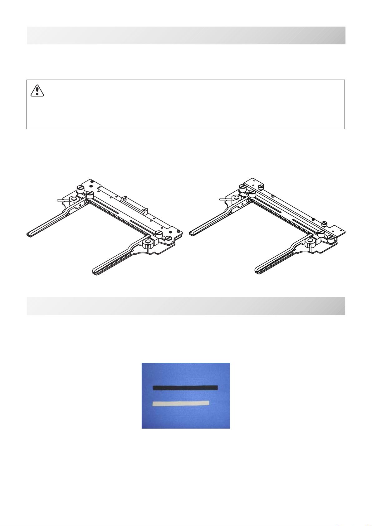
The types of side clamp frame are described below.
Use correct type of side clamp frame for your embroidery machine.
FRA21G0
Side Clamp Frame (for HCH, HCS2)
FRA21G1
Side Clamp Frame (for HCD2, HCD3)
CAUTION: To avoid problems.
To use side clamp frame , select “Special frame” from frame selection menu.
Please note that the following functions will be canceled at “Special Frame” mode.
* Frame conrmation (embroidery area of frame)
* Auto stop function when frame movement exceeds the carriage limit.
1-2
ACCESSORIES
FRA21181 Sponge (2 pcs)
FRA21191 Sheet (2 pcs)
(packed with frame)
-FC -4
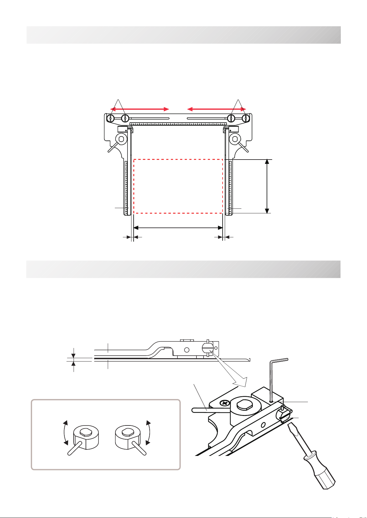
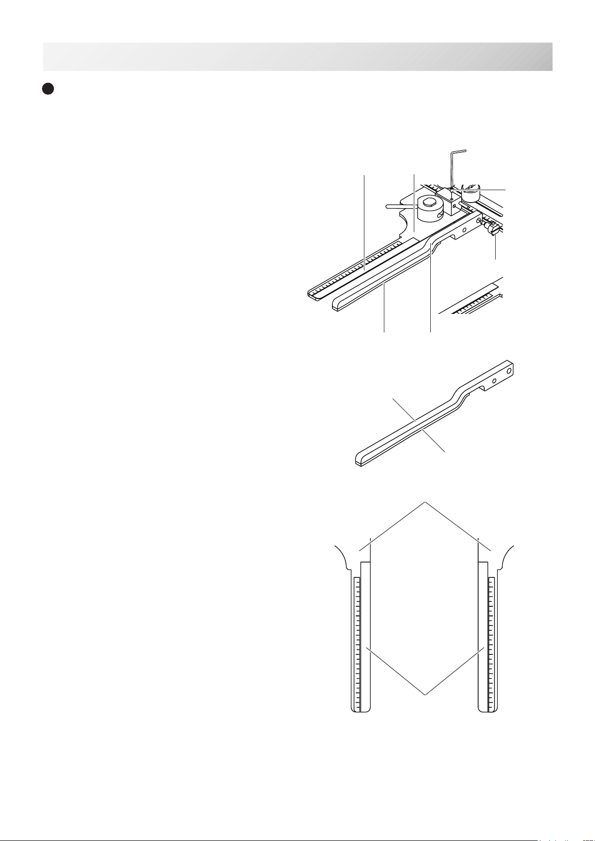
ADJUSTMENT OF EMBROIDERY AREA 2-1
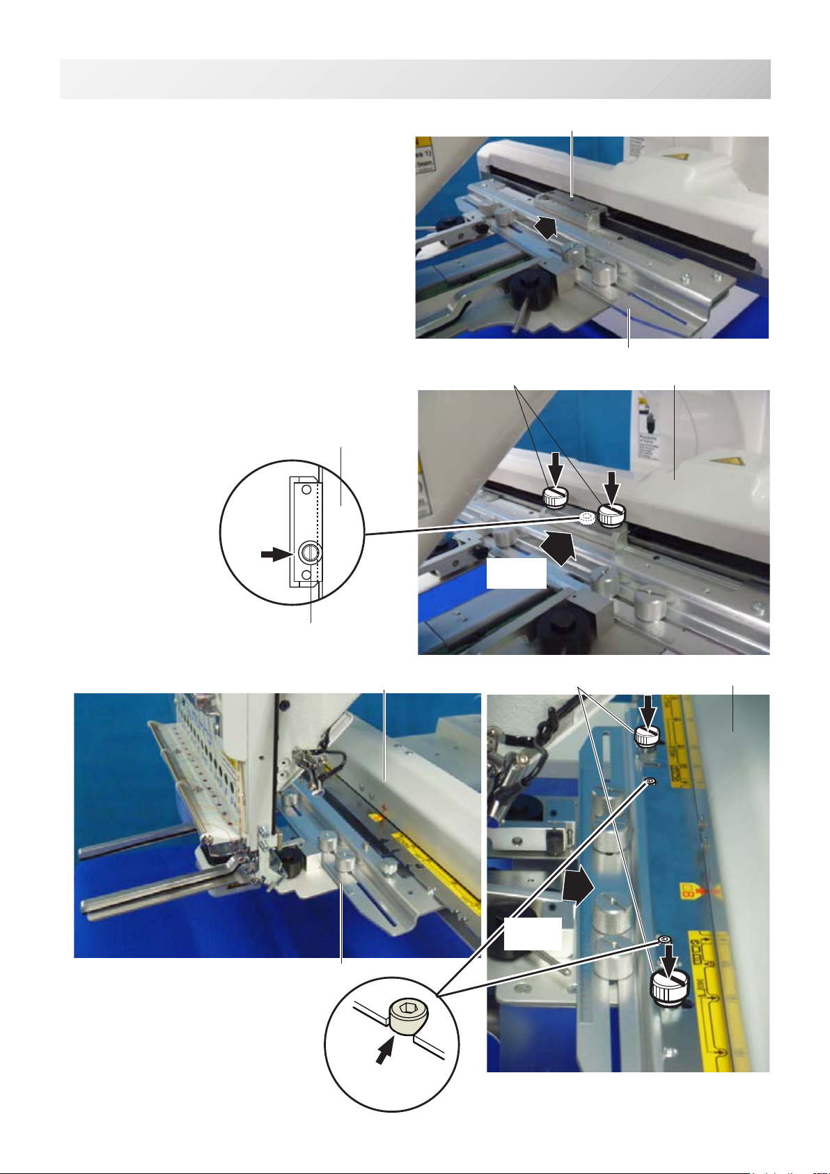
Adjust width of the upper arm to meet size of material and embroidery design.
Widthofthearmshouldhaveenoughmarginsforembroideryarea.
Loosenbothsideknobnutsforadjustmentofarm.
Tightenallknobnutsafteradjustment.
Knob nut
Arm
0 ~ 220mm
140mm
Knob nut
2_1 PA13
Pleasenotethatbasicallytheupperarmandthelowerarmshouldbeparallelatlockingposi-
tion.
Incasethethicknessofthematerialisuneven,useadjustingsetscrewandeccentricpinto
changeangleoftheupperarmtogiveholdingpressureevenly.
Lowerarm
Setscrew
Eccentricpin
Upper arm
Parallel
2-2
ADJUSTMENT OF UPPER ARM
Open
Close
Open
Close
RightLeft
Lever
Arm
5mm ~ 5mm ~
-FC -5
3-1
INSTALLING THE FRAME
Whenyouusesideclampframe,pleasemakemachinesettingaccordingtoframetypeselected.
CAUTION: To avoid problems.
Themachineand/orframemaybedamagediftheincorrectframesettingsareused.
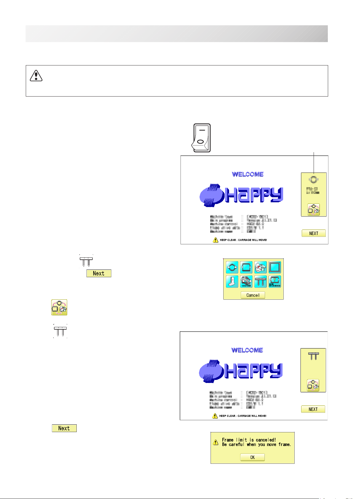
ON
OFF Selectedframe
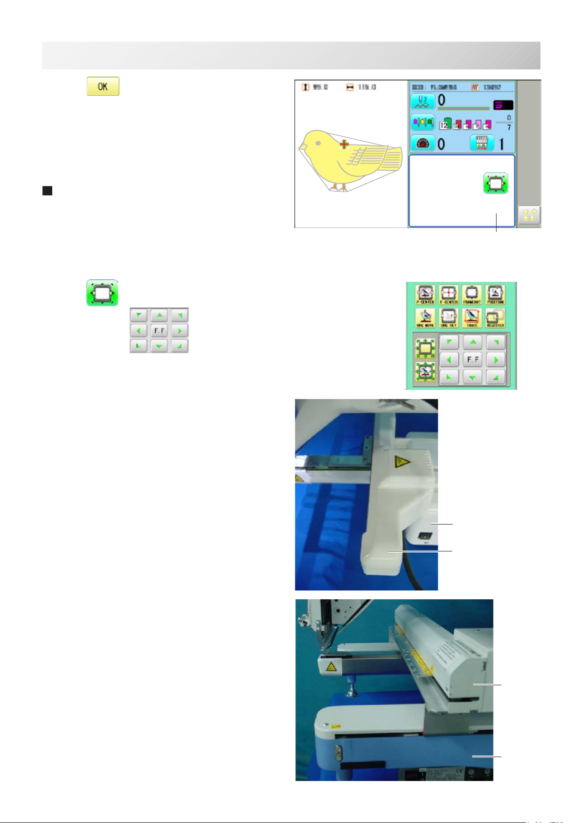
1. Turnonthepowerswitch.
Indicates the selected frame.
2. Incaserequired “Specialframe”isalready
selected,pressthe and jump to operation
no.4.
Incaseselectedframetypeisnot“Specialframe”,
press .
3. Select “Specialframe”.
4. Press .
3_1 PA13
-FC -6
3-2
INSTALLING THE FRAME
5. Press .
Iindication of frame type disappears.
It means that “Special frame” is selected.
When you need to change from Special frame to oth-
er type of frame, please powor machine off and start
again.
Without re-starting machine, machine will move in-
correctly.
6. Press and move the carriage to the position
shown by press .
Frame Iindication disappears
HCD2,
HCD3
HCH, HCS2
3_2 PA13
Machine
Carriage
Machine
Carriage
-FC -7
3-3
INSTALLING THE FRAME
7. Insertshoeframetobelowthexingbaseof
carriage by sliding on bed.
Fixknobscrewsashittingthebearing
against the carriage while pressing the side
clamp frame to the carriage.
HCD2, HCD3
HCH, HCS2
Carriage
Knob screw
Fixingbase
Side clamp frame
Carriage
Knob screw
Fixingbase
Side clamp frame
3_3 PA13
Pushing
against
Positioning bolt
Pushing
against
Bearing
Carriage
-FC-8
4-2
HOOPING MATERIAL
Lever
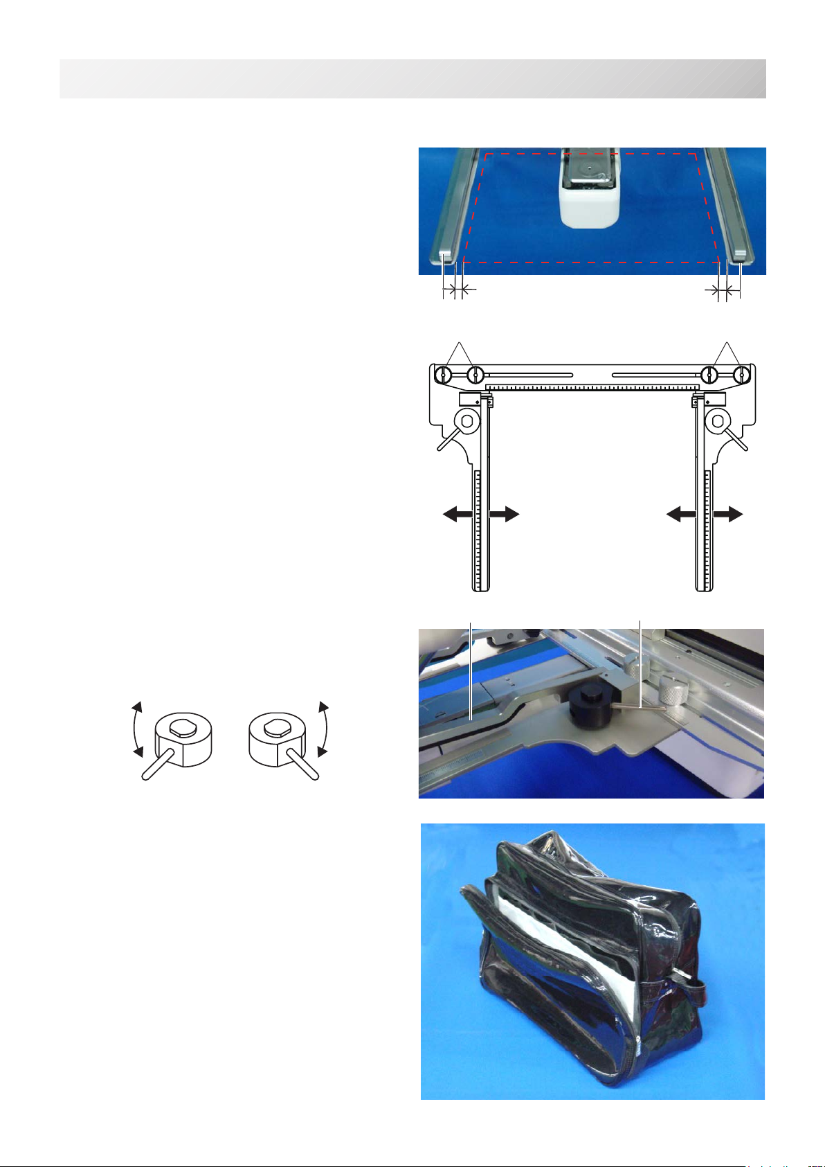
1. Adjust width of the arm to meet size of ma-
terial and embroidery design.
Widthofthearmshouldhaveenoughmar-
gins for embroidery area.
Loosenbothsideknobnutsforadjustment
of arm.
Tightenallknobnutsafteradjustment.
2. Turnrightandleftlevertoopentheupper
arm.
3. Takeoffallremovablepartslikeinsoleto
reduce weight of the bag.
Openallsidezipperstokeepthematerial
exible.
Upper arm
Knob nut Knob nut
Arm Arm
Thefollowingisanexampleforbagembroidery.
4_1 PA13
Open
Close
Open
Close
RightLeft
5mm ~ 5mm ~
-FC -9
4-2
HOOPING MATERIAL
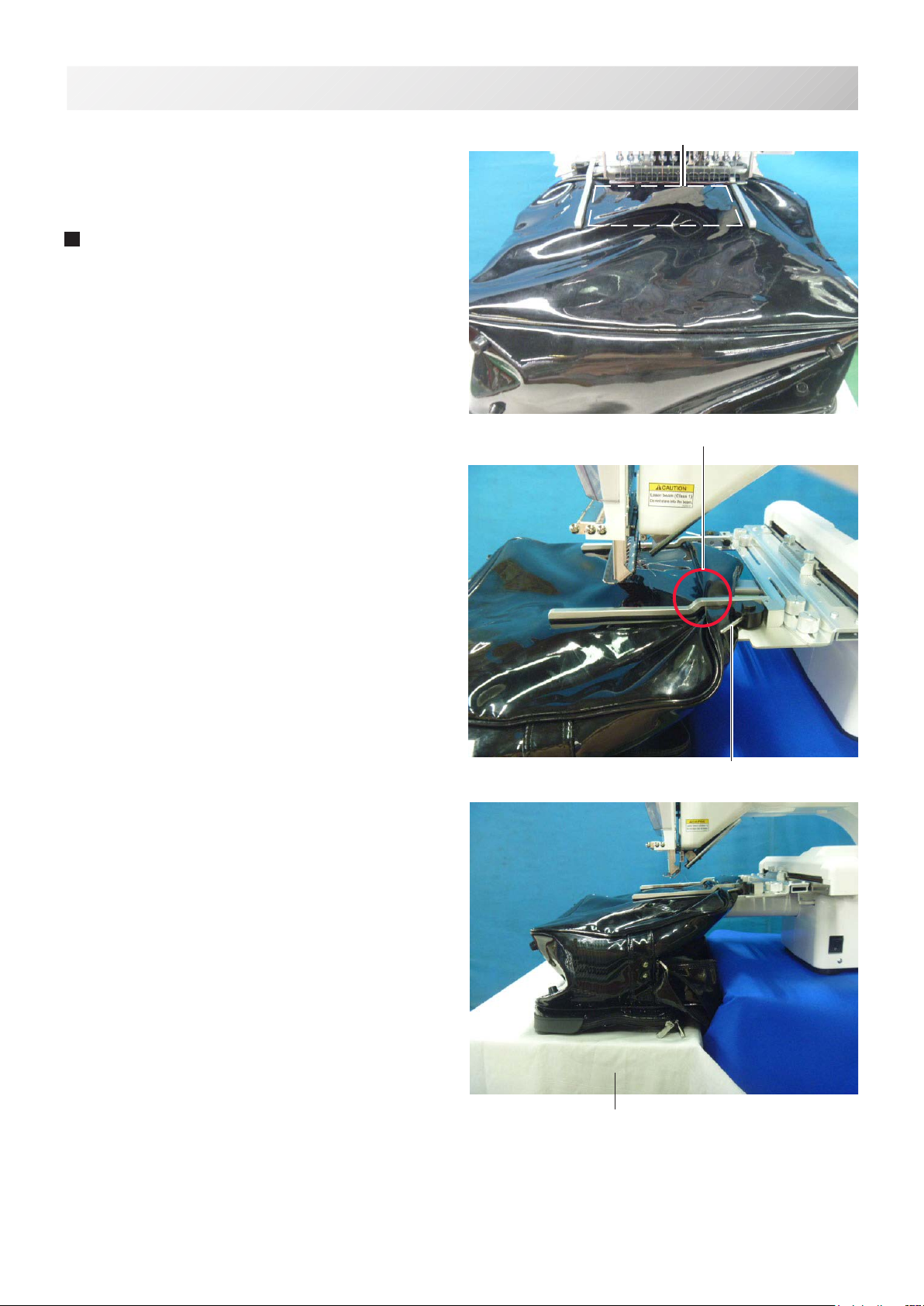
4. Turnrightandleftlever,thenthebagwillbe
locked.
Pleasemakesurethatthematerialinsideof
embroideryareaissetat.
Pleasealsocheckthatnohardmaterial
likemetalhookislocatedintheembroidery
area.
Edgeofbagshouldbesetinthespacebe-
low upper arm.
Ifthebagistooheavy,usesupporttableto
preventthearmfromslantingdown.
4_2 PA13
Embroideryarea
Spacebelowupperarm
Lever
Table (HCS2)
-FC -10
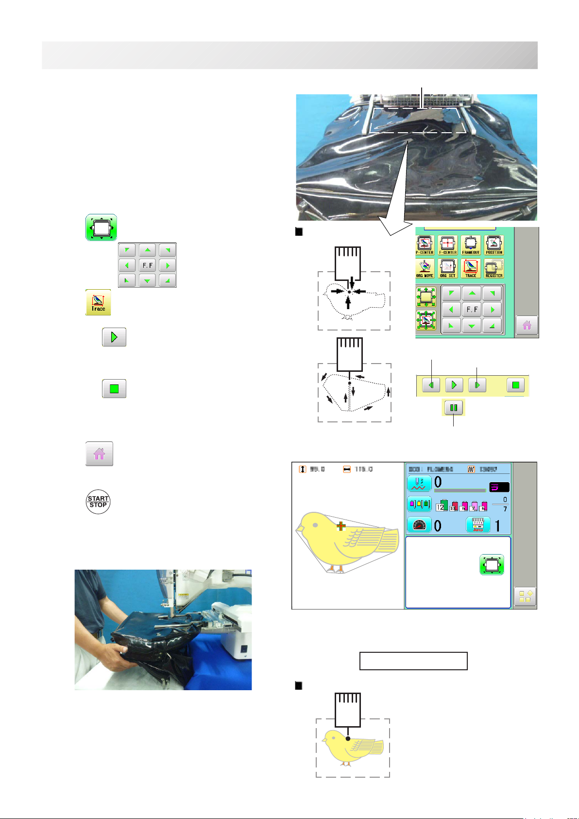
5-1
STARTING TO EMBROIDER
:Originalpoint
(Startpoint)
1. Press andmovetheframetotheoriginal
point with the .
2. Press .
Press ,andtheembroideringframemoves
for the design trace.
Youcanconrmoutlinetraceandthepositionof
the design.
Press ,andtraceisstopped.
Goontostep4ifyouwanttostartembroidering
without tracing.
3. Press after the trace is completed.
Theembroideringframehasmovedtotherst
stitch point of the pattern.
4. Press .
Theembroiderywillstart.
Handsupportisalsohelpfulwhenthearmis
slanted down due to weigh of the bag.
5. Afterembroideringyourdesigniscomplete,show
“>>End”andthemachinewillstop.
Theembroideryframereturnstotheoriginal
pointautomaticallyifthe“Autoorigin”function
hasbeenactivated.
:Originalpoint(Startpoint)
Forward only when pressing
Backwardonlywhenpressing
Youcanconrmtheoutline
and position of design.
>>End
Embroideryarea
5_1 PA13
(HCS2)
Pause button
-FC -11
6-1
ETC.
EXCHANGE SPONGE AND SHEET
Spongeandsheetarelocatedundertheupperarmandonthelowerarmtoholdfabricrmly.
Whenspongeorsheetarewornordamaged,pleaseexchangespongeorsheet.
1. Removethesetscrewanddisassemblethe
eccentric pin.
2. Removetheupperarm.
3. Removethespongeorsheetfromthe
upper arm or the lower arm.
4. Attachthespongetotwiththeedgeof
the upper arm as shown.
5. Attachthesheettotwiththeedgesofthe
lower arm as shown.
Cuttotaroundthecorner.
4. Inthereverseorderofdisassembling,x
the upper frame by screw.
Afterxtheupperframe,adjusttheupper
frameinaccordancewith“ADJUSTMENT
OFUPPERARM2-2”.
Rightside Eccentricpin
Setscrew
Upper armSponge
Sheet Lowerarm
Sheet
Upper arm
Sponge
Lowerarm
6_1 PB19
I
17
19
I
22
23
J
20
J
22
21 I
21
1
2
24
K
15
13
12
9
10
4
B
3
16
16
A
15
14
12
10
5
25
11
HCH, HCS2 HCD2, HCD3
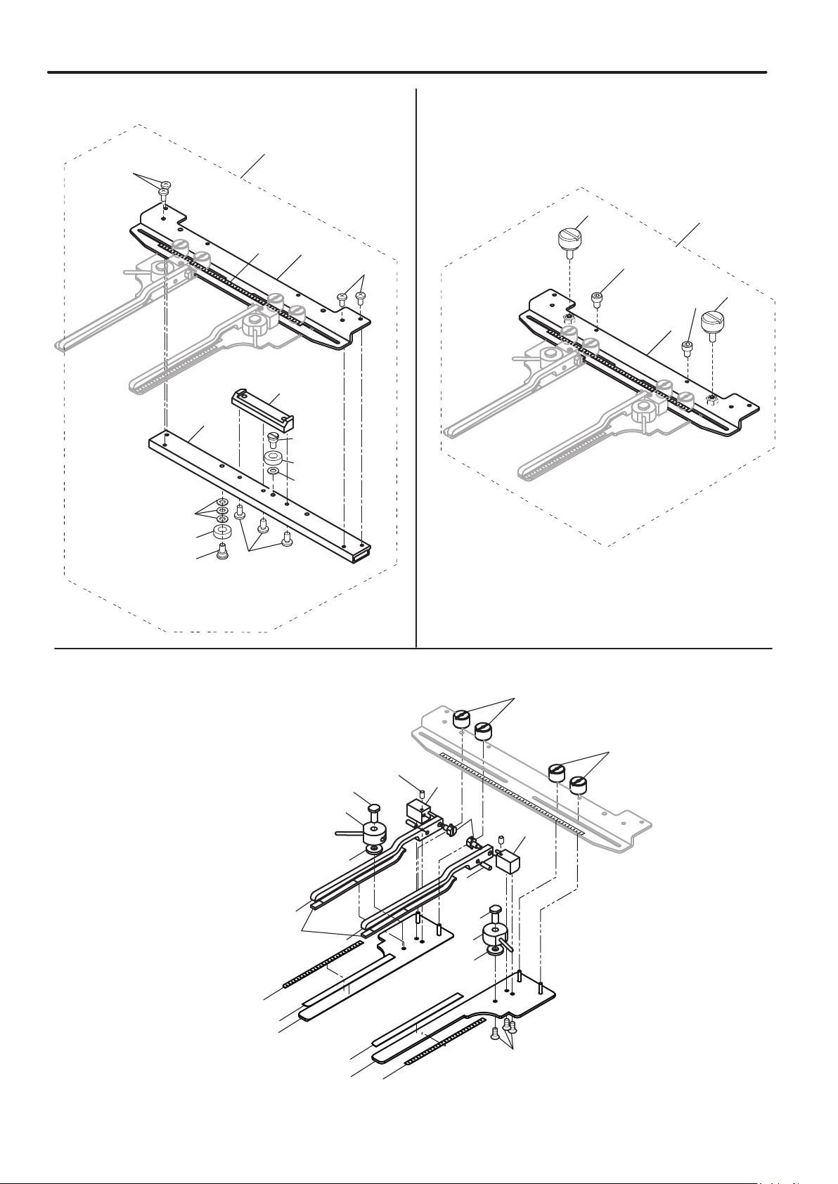
SIDE CLAMP FRAME 7-1
FCPA13
7
18
24
K
25
5
6
8

SIDE CLAMP FRAME サイドクランプ枠 7-2
指図 部品番号 部品名 FCPA15 備考
Ass'y El't Parts No. Parts Names Note
1FRA21G0 Side clamp frame ass'y (for HCH, HCS2) サイドクランプ枠組(HCH, HCS2用)
2FRA21G1 Side clamp frame ass'y (for HCD2) サイドクランプ組(HCD2, HCD3用)
3FRA21I00 Lower arm long ass'y (right) 下アームロング組(R)
4FRA21I10 Lower arm long ass'y (left) 下アームロング組(L)
5FRA21191 Sheet long 滑り止めシートロング
6FRA21F40 Fulcrum block (right) ass'y 支点ブロック(R)組
7FRA21F50 Fulcrum block (left) ass'y 支点ブロック(L)組
8FRA21I20 Upper arm long ass'y (right) 上アームロング組(R)
9FRA21I30 Upper arm long ass'y (left) 上アームロング組(L)
10 FRA21181 Sponge long 滑り止めスポンジロング
11 FRA21F60 Eccentric pin ass'y 偏心ピン組
12 MPZ04730 Washer 金属ワッシャ
13 FRA21F20 Cam (right) ass'y 溝カム(R)組
14 FRA21F30 Cam (left) ass'y 溝カム(L)組
15 FRA21340 Shaft シャフト
16 FRA21102
Knob nut
ノブナット
17 FRA21152 Connecting plate 靴枠連結板
18 FRA21B51 Connecting plate ass'y 靴枠連結板組
19 FRA21200 Scale sticker A (250mm) メモリテープA
20 HCB40041 Screw ベアリング止めネジ
21 HCB40121 Arm 連結アーム
22 HCB40132 Bracket 取付け板
23 MPB00250 Bearing (L1680ZZ) ミニチュアベアリング
24 HCD37092 Knob screw ノブネジA
25 FRA21210 Scale sticker B (140mm) メモリシールB
ASGAK04010 Flat head screw (phillips, M4x10) 十字穴付き皿小ねじ (M4×10)
BSSAA03005 Hex socket screw (M3x5) 六角穴付き止めねじ (M3×5)
ISBBK04008 Bind head screw (phillips, M4x8) 十穴付きバインド小ねじ (M4×8)
JSCAD04006 Hex socket head cap screw (M4x6) 六角穴付きボルト (M4×6)
KWPAD05000 Plain washer (M5)
平座金 (M5)

OA01E
HEAD OFFICE 3-3515, Tachiyagawa, Yamagata-city, 990-2251, Japan
Phone: +81-23-686-2272 Fax: +81-23-686-2243
TOKYO OFFICE 2-9-5, Taito, Taito-Ku, Tokyo 110-0016, Japan
Phone: +81-3-3834-0711 Fax:+81-3-3835-8917
Other manuals for HCH(Puls)
1
This manual suits for next models
3
Table of contents
Other HappyJapan Sewing Machine manuals


