HappyJapan HCD2-1501-40 User manual
Maintenance Manual for Embroidery Machine
HCD2-1501-40
Version 2.3
HappyJapan Inc.

2
# For safe adjustment and repair #
In order to conduct adjustment and repair safely and surely,
please be sure to abide by what is mentioned in this manual to prevent trouble.
1. When you conduct adjustment and repair of this embroidery machine or handle electric related parts,
you are required to take technical lesson in advance.
2. When you conduct adjustment and repair using this manual, please be sure to use together with instruction
with it in hand.
# Please conduct in accordance with work process in this manual.
# In case there are no specific instructions or explanations in work process.
please be sure to unplug cord from receptacle.
# When you exchange parts, please be sure to use genuine parts designated by us.
# Please never remodel the embroidery machine.
When you handle circuit boards:
# In order to prevent troubles from static electricity, please remove earth from human body.
# Please don't touch metal part of circuit board with bare hand as it will short-circuit
and threaten to break circuit boards.
# When you removed circuits boards from the machine or you store or transport them,
please wrap them in static electricity preventive bag and avoid to give shock.

3
Index
page
For safe adjustment and repair 2
Index 3
Special tool, Measuring equipment, Other 8
1 Outline of mechanism
1-1 Outline of mechanical mechanism. 11
1-2 Placement of key electronic parts 13
2 Outer covers
2-1 Removal of thread guide ass’y, thread guide pillar and thread stand.11
2-2 Removal of outer covers. 13
3 Mechanical mechanism.
3-1 Basic maintenance.
3-1-1 Maintenance of thread path. 17
3-1-2 Fixing of needle. 19
3-1-3 Selection of thread. 20
3-1-4 Relation between needle and upper thread. 21
3-2 Fixed head.
3-2-1 Exchange of crank ass’y. 22
3-2-2 Exchange of rod. 30
3-2-3 Exchange of
pressure foot arm ass'y 32
3-2-4 Exchange of pressure foot cam.33
3-2-5 Adjustment of the lowest needle point. 35
3-2-6 Exchange of needle bar driver. 36
3-2-7 Adjustment of fixing of jump device 37
3-2-8 Exchange of roller shaft ass’y. 38
3-2-9 Adjustment of take-up lever timing. 39
3-2-10 Check of height of pressure foot. 40
3-2-11 Exchange / Adjustment of pressure foot 41
3-2-12 Fixing of thread catcher. 43

4
Index
page
3-3 Moving head.
3-3-1 Assemble and remove moving head. 45
3-3-2 Fixing of upper rail. 48
3-3-3 Adjustment of backlash (back and forth) of moving head. 49
3-3-4 Adjustment of needle position (back and forth). 50
3-3-5 Check of needle position. 51
3-3-6 Adjustment of needle height. 52
3-3-7 Exchange of needle bar, needle bar spring, cushion and pressure foot block.54
3-3-8 Fixing of needle bar boss check plate 56
3-3-9 Exchange of take-up lever 57
3-3-10 Adjustment of thread holder 59
3-3-11 Exchange of majic-tape on thread holder 60
3-3-12 Exchange of TC8-7 Thread detecting board (Rev. A) 60a
3-4 Needle bar change unit
3-4-1 Fixing of needle bar change unit 61
3-4-2 How to take out needle bar change stop position sensor 62
and needle position sensor (potentiometer)
3-4-3 Setting to detect needle position 63
3-5 Rotary hook
3-5-1 Exchange and adjustment of rotary hook timing 65
3-5-2 Adjustment of retainer on rotary hook 67
3-6 Thread cut unit
3-6-1 Adjust for thread trim sensor and stopper 68
3-6-2 Exchange of moving knife 70
3-6-3 Exchange of fixed knife 71
3-6-4 Adjustment of moving knife and fixed knife 72
3-6-5 Adjustment of position of moving knife 73
3-6-6 Adjustment of bobbin thread holder 74
3-6-7 Exchange of keeper solenoid 75
3-6-8 Adjustment of position of keeper 77

5
Index
page
3-7 Carriage unit
3-7-1 Adjustment of X carriage belt tension 78
3-7-2 Exchange of X carriage belt 80
3-7-3 Adjustment of Y carriage belt tension 82
3-7-4 Exchange of Y carriage belt 85
3-7-5 X carriage limit sensor replacement and adjustment 88
3-7-6 Y carriage limit sensor replacement and adjustment 89
3-8 Transmission unit
3-8-1 Adjustment of timing belt tension 90
3-8-2 Exchange of timing belt 91
3-8-3 Exchange of main shaft timing board 93
3-8-4 Adjustment of detecting slit and timing slit 94
4 Exchange and Setting of electric related component
4-1 Exchange of fuse. 90
4-2 Exchange of CONT-D2 board 91
4-3 Exchange of switching power supply and adjustment
of power voltage output and of power failure detection
4-3-1 Exchange of switching power supply 98
4-3-2 Adjustment voltage output of 24V switching power supply. 100
4-3-3 Adjustment voltage output of 36V switching power supply. 101
4-4 Exchange of cooling fan (2 places) 102

6
Index
Page
5 Parts Replacement in control box and setting
5-1-1 Remove control box 103
5-1-2 Remove LCD-CE board 104
5-1-2a 10.4” Remove LCD-CE board 105a
5-1-3 Setting for LCD-CE board 106
6 Exchange and setting of Inverter
6-1 Exchange Inverter
6-1-1 Remove Inverter 107
6-1-2 Inverter Installation 109
6-2 Setting of inverter
6-2-1 How to set inverter 112
6-2-2 Initialization of parameter 114
7 Program update procedure 115
7-1 Preparation for program update 116
7-2 Machine program update 117
7-3 Main program update 119
7-3a Main program update 120
7-4 Setting of revolution 121
Re-Initialization of machine system
Initializing of machine speed
8 Maintenance mode 122
8-1 How to enter Maintenance mode 122
8-2 Machine Test Machine movement 123
8-3 Memory All Clear Initialization of design memory 125
8-4 Record Opereration data display 126
8-4-1 Total number of stitch 126
8-4-2 Record of Error occurrence 127
8-4-3 Number of occurrence in each error display 128
8-4-4 Thread break history 129
8-5 Machine setting 130
8-6 Frame Position Entry Registration of coordinates for positioning sensor. 132
8-7 Maintenance Register―Registration of machine maintenance date 133a
8-8 Machine Setting Navigation after exchanging CONT board (Main program Ver.*1.34~) 133b

7
Index
Page
9 Installment and setting of option unit
9-1 Installment, setting and adjustment of needle sensor 134
9-1-1 Installment of safety sensor 134
9-1-2 Setting procedure. 137
9-1-3 Adjustment of optical axis. 138
9-2 Installment of Bobbin winder 139
10 Electric system diagram
10-1 Electrical connection diagram (before Rev. A) (for LCD-CE board) 143
10-2 Electrical connection diagram (before Rev. A) (for LCD-CE-U, LCD-CE-MX board) 146
10-2a Electrical connection diagram (Rev. A) 149a
10-3 Connection of inverter 150
10-4 Explanation of function of circuit board 151
11 Others
11-1 How to respond for some question ( As example step) 157
11-2 Trouble shooting
11-2-1 Electricity doesn’t turn on 158
11-2-2 Thread break 159
11-2-3 Erraneous thread cut 164
11-2-4 Off-registration of pattern 166
11-2-5 Upper thread comes off from needle hole 169
11-2-6 Upper thread remains 171
11-2-7 Malfunction of thread break detection 172
11-2-8 Suspension of upper shaft 174
11-2-9 Malfunction of needle bar change 175
11-2-10 Defect on thread catcher 176
11-2-11 Others (Mechanical) 177
11-2-12 Others (Electronically) 178
11-3 Error
11-3-1 Startup error and measure (Main program Ver.*1.37~) 178a
11-3-2 Error and measure 179
11-4 Reference date
11-4-1 Tables for timing / adjustment value 184

8
Special tool, Measuring equipment, Other
HSA90020
2.0mm thickness gauge (Page 76)
HSA90030
Keeper positioning gauge (Page 77)
HSA90051
Bering positioning gauge [4.85mm] (Page 38)
HSA90080
Retainer positioning gauge [0.8mm] (Page 67)
HSA90090
Positioning pin (Page 39)
HSA90131
1.2mm thickness gauge (Page 40, 42)
9
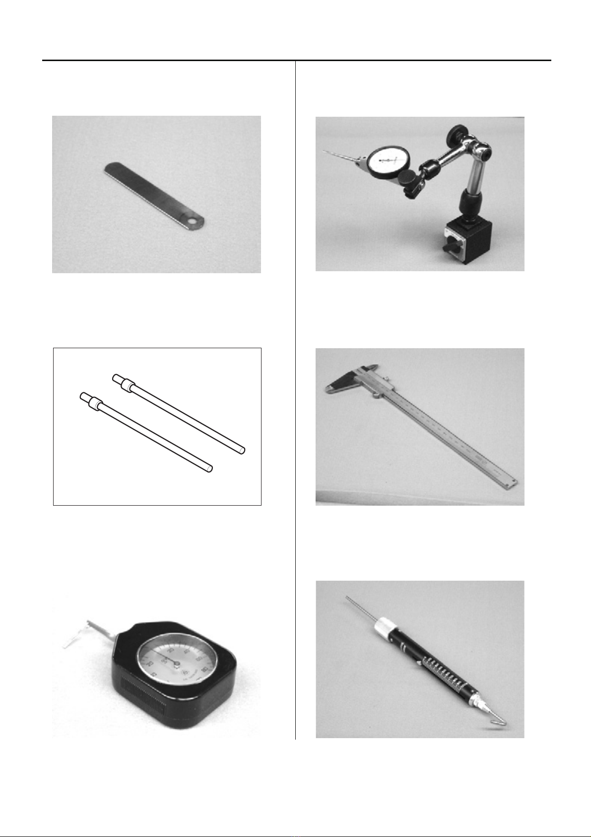
HSA90210
0.2mm thickness gauge (Page 58)
HSA90220
6mm positioning pin (Page 87)
HSA90230
Tensile gauge (Page 74)
HSA90240
Dial-gauge set (Page 35)
HSA90270
Vernier calliper gauge [200mm] (Page 34)
HSA90300
Tension gauge 2000cN (Page 78, 83)

10
HSA90311
Shell alvania EP Grease2 100g
(Page 31, 33, 36)
M0404342
Needle height gauge (Page 52)
11
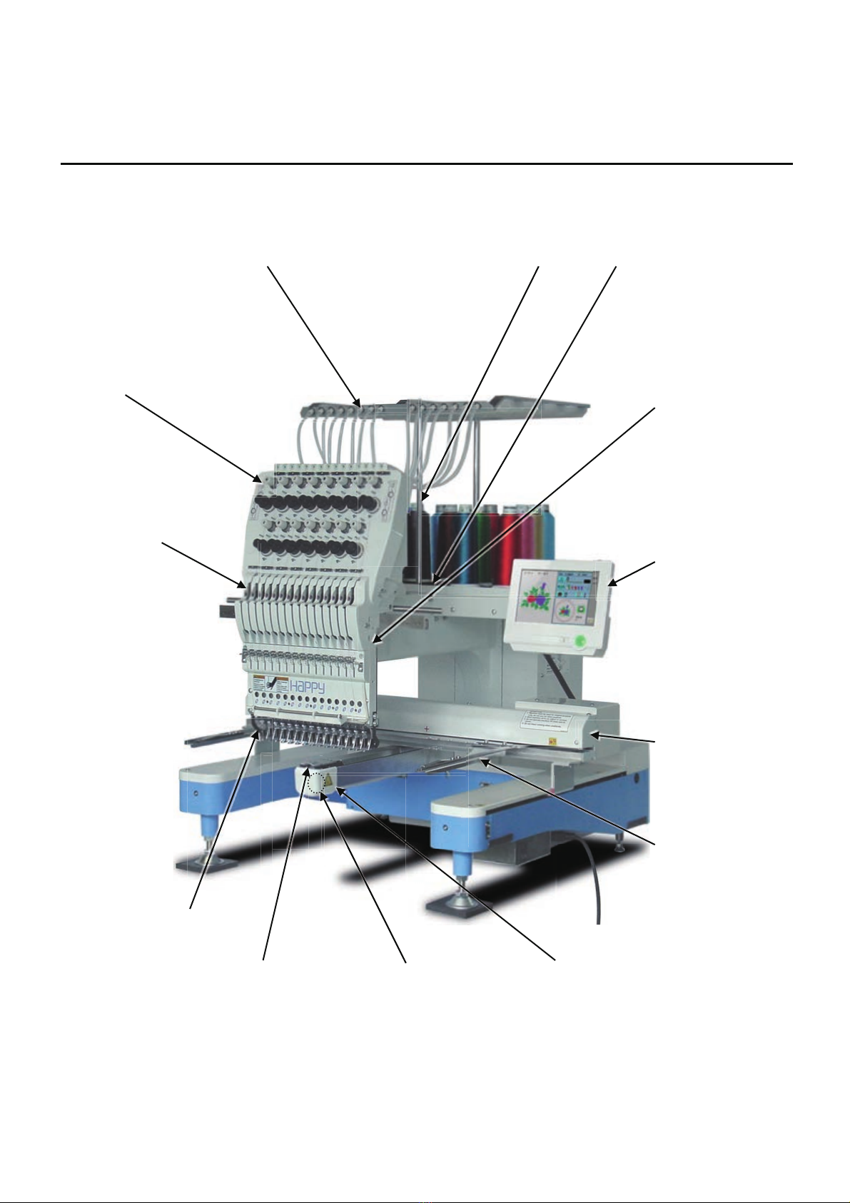
1-1 Outline of mechanical mechanism
Thread guide bracket Thread guide pillar Tread stand
Thread tension unit
Moving head
Take-up lever
Control panel
X carriage
Frame base
Thread holder
Needle plate Rotary hook Rotary hook cover

12
Needle bar change unit
Thread cutting
driver
Needle bar driver unit
Thread holder
Y carriage
Upper shaft Take-up lever cam Thread cacher

13
1-2 Placement of key electronic parts
Pulse motor (Needle bar change unit)
CONT-D2
TC board board
Emergency stop switch
Control box
Fuse
Power switch
AC power
Timing board
Inverter
Main motor
Power supply
wi
itch
h

14
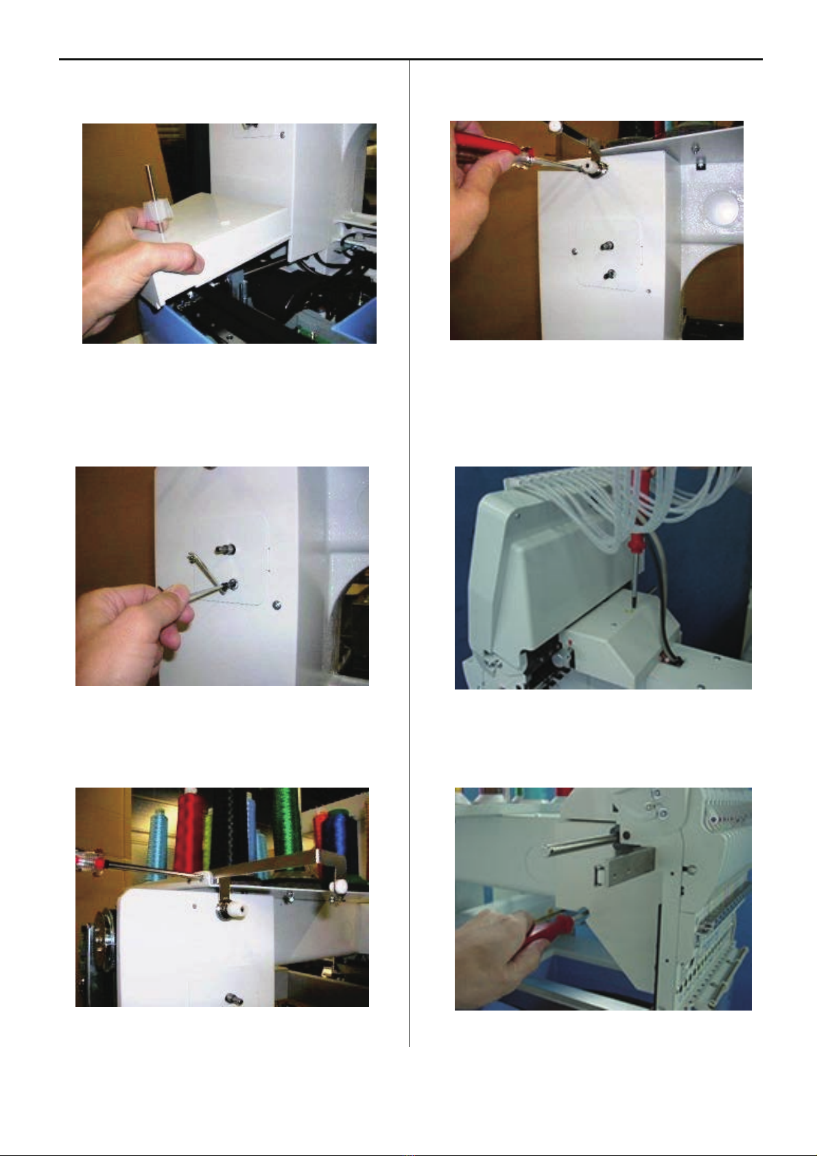
2-1 Removal of thread guide ass’y, thread guide pillar and thread stand
1. Remove all the tube holders from thread tension.
Tube holders are removed by pulling the tube holder
upward.
2. Remove 2 fixing screws and thread guide bracket.
3. Remove thread guide pillar and thread stand.
4. Remove 8 fixing screws and thread stand.
15
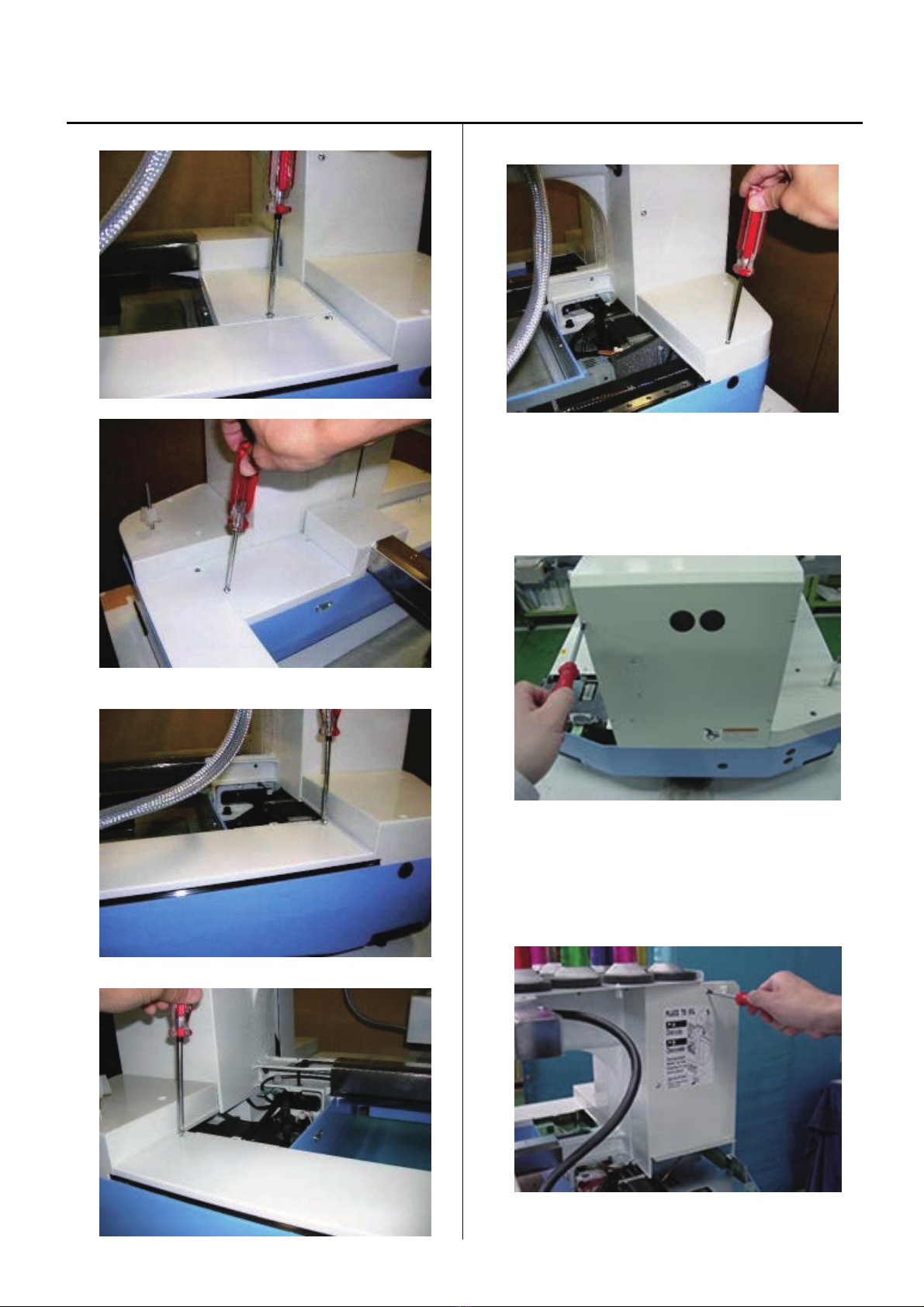
2-2 Removal of outer covers
1. Remove the cover G ass'y. (Fixing screw 4 pcs)
2. Remove the cover E. (Fixing screw 2 pcs)
3. Remove the cover F. (Fixing screw 2 pcs)
4. Remove the cover C. (Fixing screw 2 pcs)
5. Remove the cover H. (Fixing screw 6 pcs)
6. Remove the cover A. (Fixing screw 2 pcs)
16
7. Remove the cover D. (Fixing screw 2 pcs)
8. Guide should be removed if there is a bobbin winder.
(Fixing screw 1 pcs)
Remove the bobbin thread guide. (Fixing screw 2 pcs)
9. Remove the cover B. (Fixing screw 2 pcs)
10. Remove the cover for needle bar change unit.
(Fixing screw 2 pcs)
11. Remove the head left side cover. (Fixing screw 2 pcs)
12. By above process, removal of [cover] has finished.
17
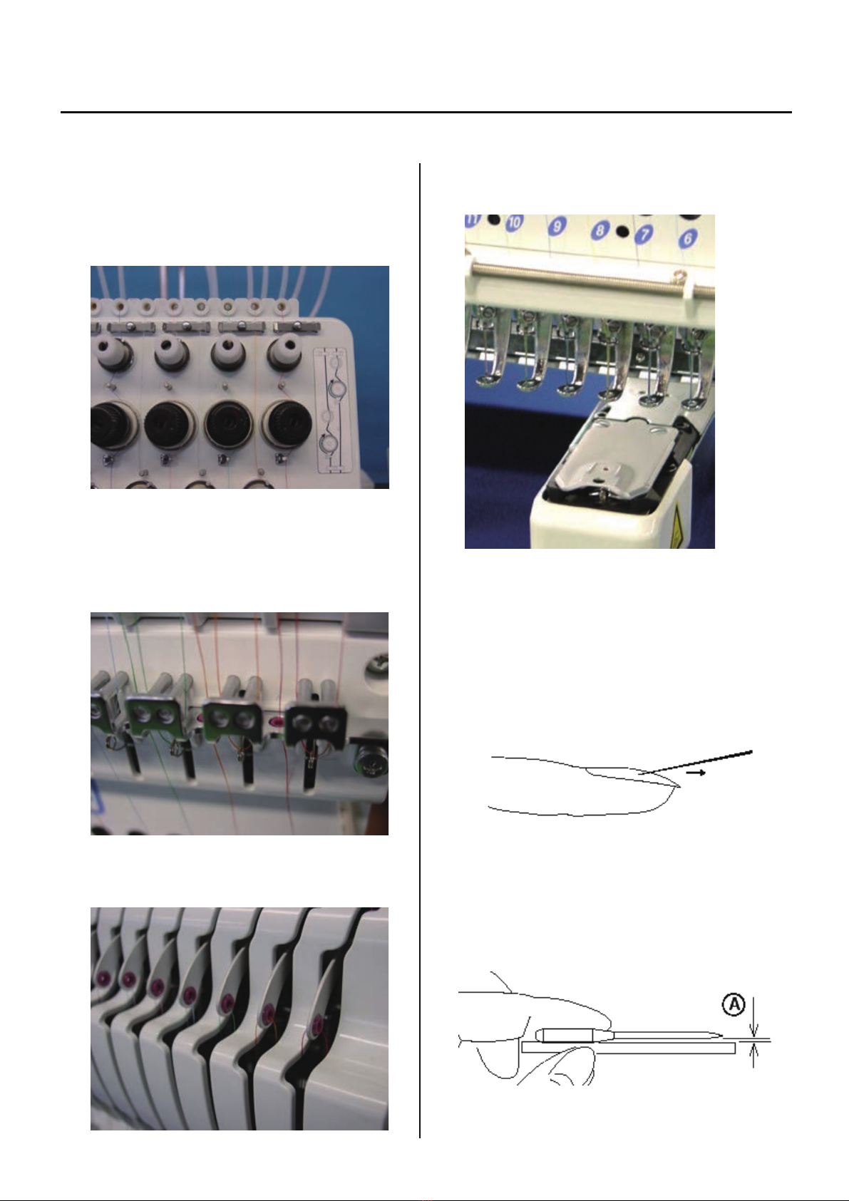
3-1-1 Maintenance of thread path
In a bid to prevent poor sewing finish or thread break, please keep places where thread contacts in the best condition.
1. Thread tension, detecting roller, thread adjusting spring
a) Revolution must be smooth
b) No sticking of lint or dust
2. Thread Adjusting Spring, holes on thread guide plate
a) No burr and crack
3. Ceramic and rim of take-up lever
a) No burr and crack
4. Thread path in lower side and needle holder.
a) No burr and crack
5. Needle
a) Needle tip shouldn't be warped or bent.
When you slide needle tip on surface of nail and
if the nail gets scratched.
needle tip is warped. Please exchange it with new one.
Please place needle on flat surface and check
clearance (A) from side.
If clearance is not equal, needle is bent.
Please replace it with new one.
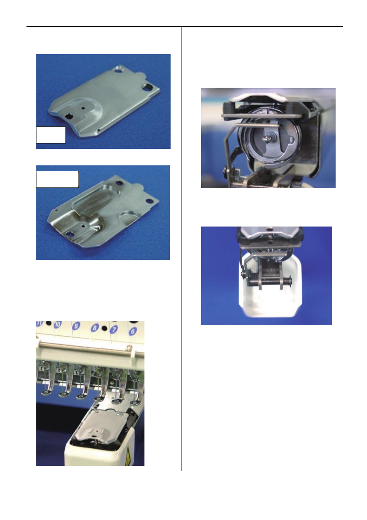
18
6. Needle plate
a) No burr and crack in needle hole and around it.
7. Pressure foot
a) No burr and crack inside hole
b) Not bent
8. Rotary hook
a) No burr and crack.
b) Hook point not warped.
c) Backlash between bobbin case holder and outer hook
should be less.
9. Keeper
a) No burr and crack on tip.
Surface
Two setscrews
19
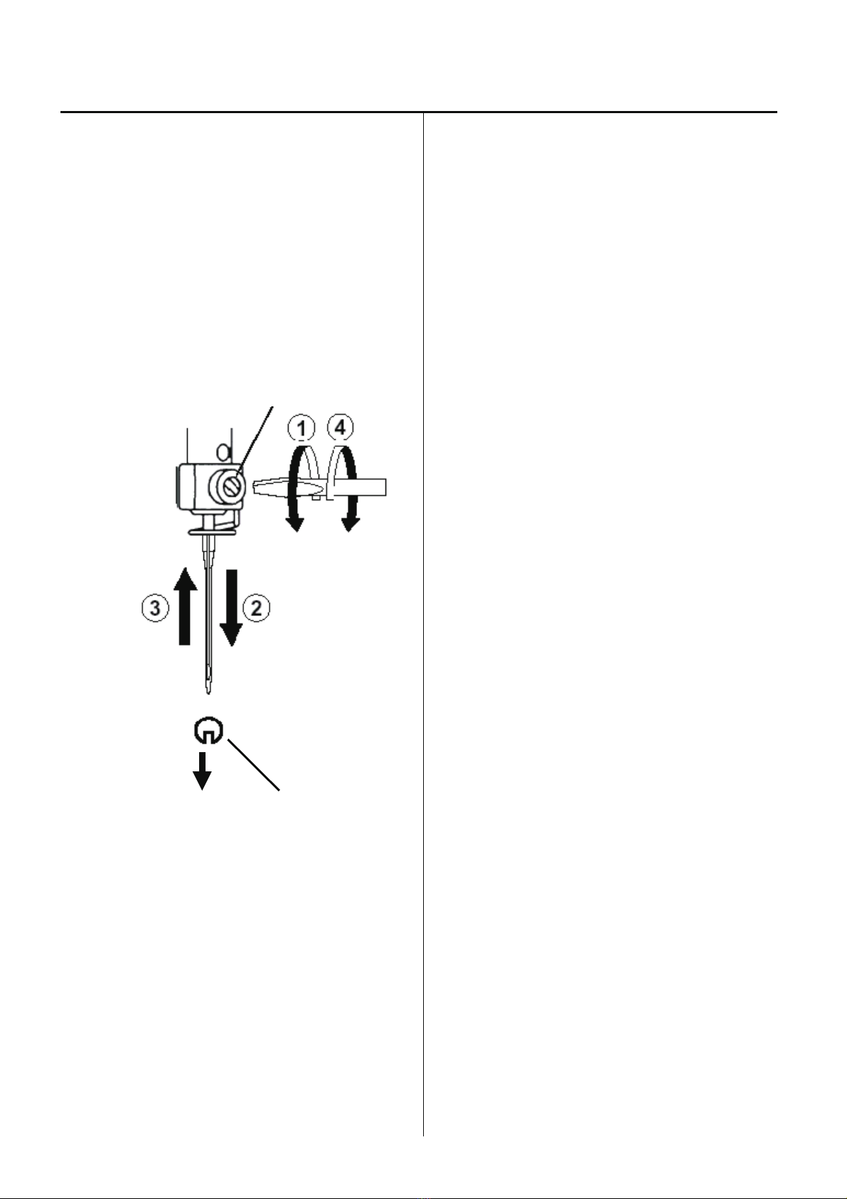
3-1-2 Fixing of needle
1. In order of (1)-(4), please remove and fix needle.
(1) Loosen screw holding needle.
(2) Remove needle.
(3) Insert needle till it goes to the end.
(4) Tighten screw holding needle.
Fix needle so that needle groove faces front.
Needle holder
Needle
Front

20
3-1-3 Selection of thread
1. Selection of upper thread.
<Description>
Please select considering cloth, design of pattern and flavor etc.
<Thickness>
Please refer to [Relation between needle and upper thread 3-1-4].
<Twist>
Z twisted thread is to be used.
(As rotary hook turns left- wise, Z twisted thread can prevent loosening of twist)
Z-twisted S-twisted
(Left - twisted) (Right - twisted)
2. Selection of lower thread.
Basically please use cotton thread (#80-120), #120 is recommendable.
Pay attention to the following in selection.
# Thickness should be equal.
# When it is lightly stretched, it doesn't break easily.
# In process of time, it doesn't get inferior.
Commercially available paper bobbin can be used, but please select thread with
thickness corresponding to cotton thread (#80-120).
Table of contents
Other HappyJapan Sewing Machine manuals


 User manual")


