HappyJapan HCH-701-30 User manual
Maintenance Manual for Embroidery Machine
HCH-701-30
Version 2.4
HappyJapan Inc.

2
# For safe adjustment and repair #
In order to conduct adjustment and repair safely and surely,
please b42e sure to abide by what is mentioned in this manual to prevent trouble.
1. When you conduct adjustment and repair of this embroidery machine or handle electric related parts,
you are required to take technical lesson in advance.
2. When you conduct adjustment and repair using this manual, please be sure to use together with instruction
with it in hand.
# Please conduct in accordance with work process in this manual.
# In case there are no specific instructions or explanations in work process.
please be sure to unplug cord from receptacle.
# When you exchange parts, please be sure to use genuine parts designated by us.
# Please never remodel the embroidery machine.
When you handle circuit boards:
# In order to prevent troubles from static electricity, please remove earth from human body.
# Please don't touch metal part of circuit board with bare hand as it will short-circuit
and threaten to break circuit boards.
# When you removed circuits boards from the machine or you store or transport them,
please wrap them in static electricity preventive bag and avoid to give shock.

3
Index
page
For safe adjustment and repair 2
Index 3
Special tool, Measuring equipment, Other 7
1 Outline of mechanism
1-1 Outline of mechanical mechanism 10
1-2 Placement of key electronic parts 12
2 Outer covers
2-1 Removal of outer covers 13
3 Mechanical mechanism
3-1 Basic maintenance
3-1-1 Maintenance of thread path 18
3-1-2 Fixing of needle 20
3-1-3 Selection of thread 21
3-1-4 Relation between needle and upper thread 22
3-2 Fixed head
3-2-1 Exchange of crank 23
3-2-2 Exchange of rod 27
3-2-3 Adjustment of the lowest needle point 28
3-2-4 Exchange of needle bar driver 29
3-2-5 Adjustment of fixing of jump device 31
3-2-6 Exchange of take-up lever cam 33
3-2-7 Exchange of roller shaft ass’y 34
3-2-8 Adjustment of take-up lever timing 35
3-2-9 Exchange of pressure foot cam 36
3-2-10 Check of height of pressure foot 37
3-2-11 Exchange of pressure foot 38
3-2-12 Adjustment of height of pressure foot guide bar 39
3-2-13 Exchange of pressure foot link and block 40
3-2-14 Exchange of pressure foot drive lever 41
3-2-15 Exchange of pressure foot guide 44
3-2-16 Exchange of pulse motor for pressure foot 45
3-2-17 Adjustment of pressure foot bracket ass’y 47

4
Index
page
3-2-18 Exchange of thread catcher 48
3-2-21 Adjustment of bobbin winder 50
3-3 Moving head
3-3-1 Assemble the upper rail of moving head 52
3-3-2 Adjustment of backlash (back and forth) of moving head 53
3-3-3 Assemble the moving head 54
3-3-4 Adjustment of needle position (back and forth) 58
3-3-5 Check of needle position 59
3-3-6 Adjustment of needle height 60
3-3-7 Exchange of needle bar and needle bar spring 62
3-3-8 Fixing of needle bar boss guide plate 64
3-3-9 Exchange of take-up lever 66
3-3-10 Exchange of thread adjusting spring 67
3-3-11 Adjustment of tension of thread adjusting spring 68
3-3-13 Adjustment of thread holder 69
3-3-14 Exchange of majic-tape on thread holder 71
3-4 Needle bar change unit
3-4-1 Fixing of needle bar change unit 72
3-5 Rotary hook
3-5-1 Adjustment of rotary hook timing 74
3-5-2 Adjustment of retainer on rotary hook 76
3-6 Thread cut unit
3-6-1 Assemble the arm ass’y 77
3-6-2 Exchange of pulse motor for thread cutting driver 79
3-6-6 Exchange of moving knife 82
3-6-7 Exchange of fixed knife 83
3-6-8 Adjustment of moving knife and fixed knife 84
3-6-9 Adjustment of position of moving knife 85
3-6-10 Adjustment of bobbin thread holder 87
3-6-11 Exchange of keeper solenoid 88
3-6-12 Adjustment of position of keeper 89

5
Index
page
3-7 Carriage unit
3-7-1 Adjustment of X carriage belt tension 90
3-7-2 Exchange of X carriage belt 92
3-7-3 Adjustment of Y carriage belt tension 95
3-7-4 Exchange of Y carriage belt 97
3-8 Transmission unit
3-8-1 Adjustment of timing belt tension 100
3-8-2 Exchange of timing belt 101
3-8-3 Adjustment of motor belt tension 103
3-8-4 Exchange of motor and motor belt 105
4 Electricity
4-1 Circuit board related parts
4-1-1 Remove LCD and LCD-CE board 107
4-1-2 Setting for LCD-CE board 109
4-1-3 Setting for power supply 110
4-2 Sensors
4-2-1 Adjustment of upper shaft timing (C point / L point) 111
4-2-2 Adjustment of TC board 112
4-2-3 Adjustment of stop position of needle bar change unit 112
4-3 Initialization of system
4-3-1 Program update procedure 113
4-3-2 Preparation for program update 114
4-3-3 Machine program update 115
4-3-4 Main program update 117
4-3-5 Setting of revolution 118
4-4 Maintenance mode.
4-4-1 How to enter maintenance mode 119
4-4-2 Machine Test Machine movement 120
4-4-3 Memory All Clear Initialization of memory 122

6
Index
Page
4-4-4 Record Opereration data display 123
4-4-4-1 Total number of stitch 123
4-4-4-2 Record of Error occurrence 124
4-4-4-3 Number of occurrence in each error display 125
4-4-4-4 Thread break history 126
4-4-4-5 Machine setting 127
4-4-4-6 Maintenance Register―Registration of machine maintenance date 127a
4-4-4-7 Machine Setting Navigation after exchanging CONT board (Main program Ver.*1.34~) 127b
5 Electrical connection diagram 128
7 Others
7-1 How to respond for some question ( As example step) 131
7-2 Trouble shooting
7-2-1 Electricity doesn’t turn on 132
7-2-2 Thread break 133
7-2-3 Erraneous thread cut 138
7-2-4 Off-registration of pattern 140
7-2-5 Upper thread comes off from needle hole 142
7-2-6 Upper thread remains 144
7-2-7 Malfunction of thread break detection 145
7-2-8 Suspension of upper shaft 147
7-2-9 Malfunction of needle bar change 148
7-2-10 Defect on thread catcher 149
7-2-11 Others (Mechanical) 150
7-2-12 Others (Electronically) 151
7-3 Error
7-3-1 Startup error and measure (Main program Ver.*1.37~) 151a
7-3-2 Error and measure 152
7-4 Reference date
7-4-1 Tables for timing / adjustment value 155
7-4-2Use TAJIMA made tubular frame 156
7
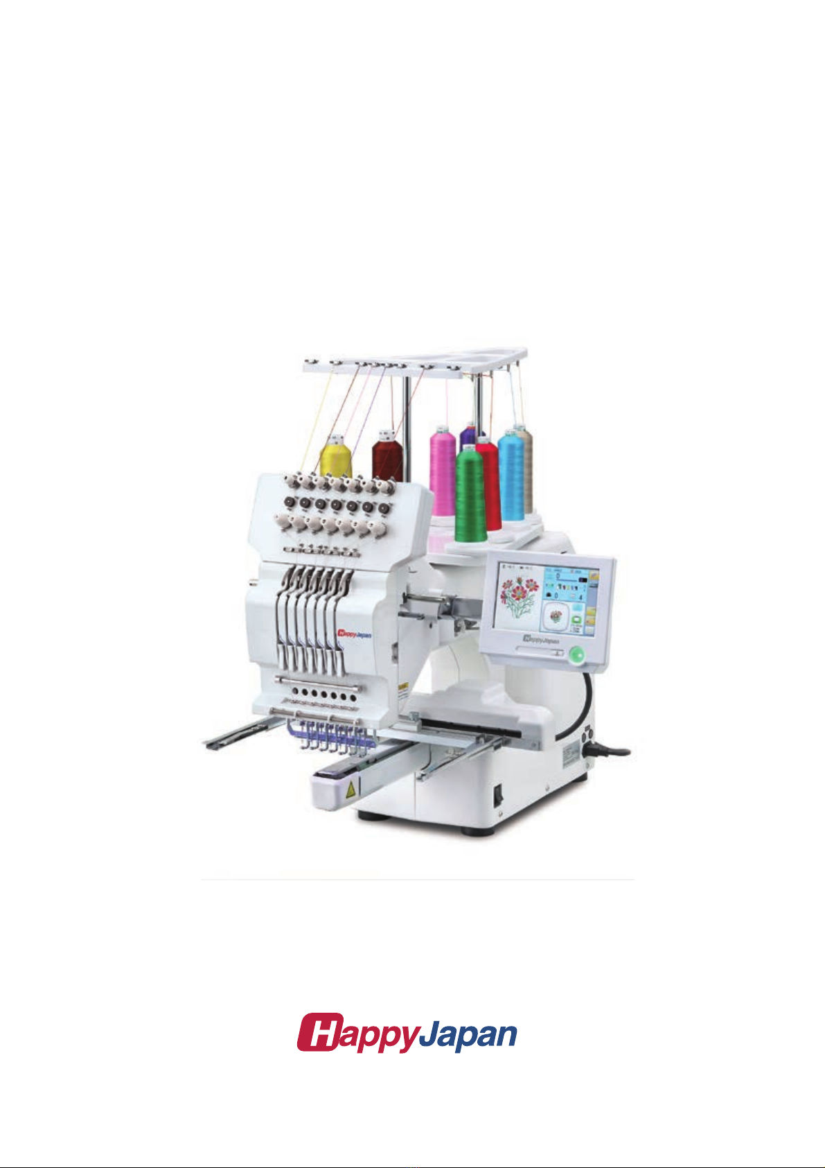
Special tool, Measuring equipment, Other
HSA90020
2.0mm thickness gauge (Page 88, 89)
HSA90030
Keeper positioning gauge (Page 89)
HSA90050
Bering positioning gauge [4.85mm] (Page 34)
8
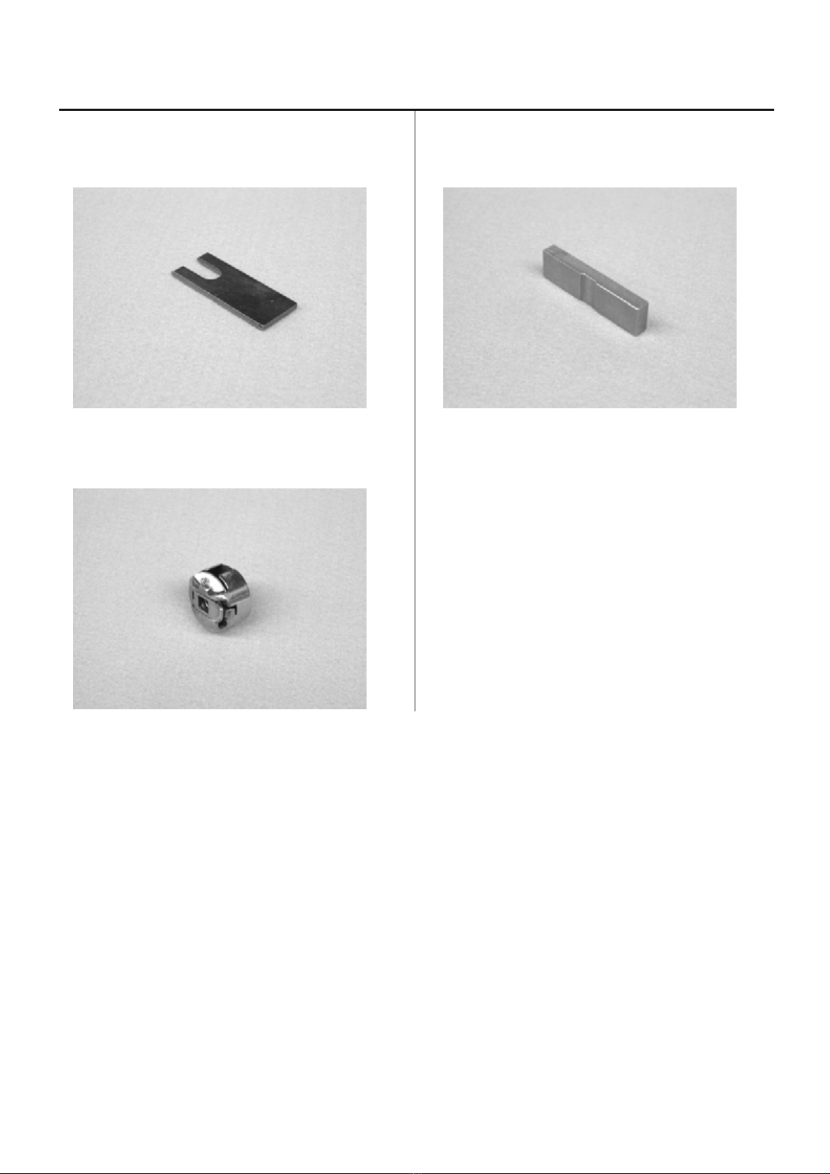
Special tool, Measuring equipment, Other
HSA90080
Retainer positioning gauge [0.8mm] (Page 76)
HSA90090
Positioning pin (Page 35)
HSA90131
1.2mm thickness gauge (Page 37)
HSA90200
0.03mm thickness gauge (Page 27, 66)
HSA90230
Tensile gauge (Page 87)

9
Special tool, Measuring equipment, Other
HSA90240
Dial-gauge set (Page 28)
HSA90270
Vernier calliper gauge [200mm]
HSA90280
Tension gauge 1000cN (Page 91, 95, 103)
HSA90311
Shell alvania EP Grease 100g
(Page 36, 42)
M0404342
Needle height gauge (Page 61)

10
Outline of mechanical mechanism 1-1
Thread guide bracket Thread guide pillar Tread stand
Thread tension unit
Moving head
Take-up lever
Control panel
Front cover
X carriage
Thread adjusting spring
Frame base
Thread holder
Needle plate Rotary hook Rotary hook cover
C
over
over
ng
g

Outline of mechanical mechanism 1-1
Needle bar
driver unit
Y carriage
Thread cutting driver Upper shaft Take-up lever cam Thread cacher
Needle bar change unit
Pressure foot driver unit
Thread holder

12
Placement of key electronic parts 1-2
Pulse motor (Needle bar change unit) CONT-J board
TC board
Display board
Fuse
Pulse motor (Pressure foot ) Power swich Noise filter AC power
Timing detecting board
Main motor
Power supply Pulse motor (Thread catcher)

Removal of outer covers (THREAD STAND) 2-1
1. Remove thread guide bracket.
2. Loosen a screw of thread guide pillar
3. Remove thread guide pillar and thread stand.

14
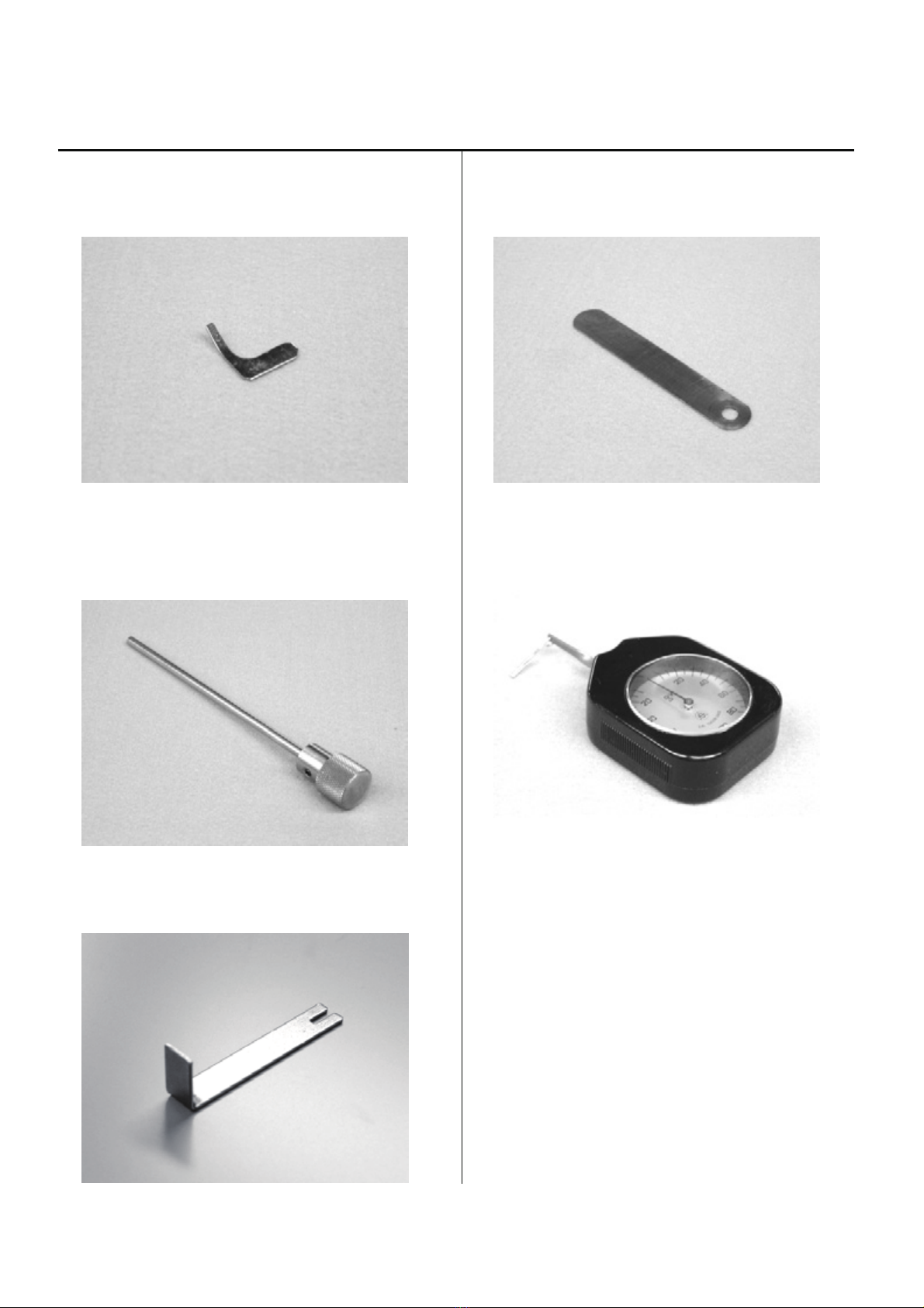
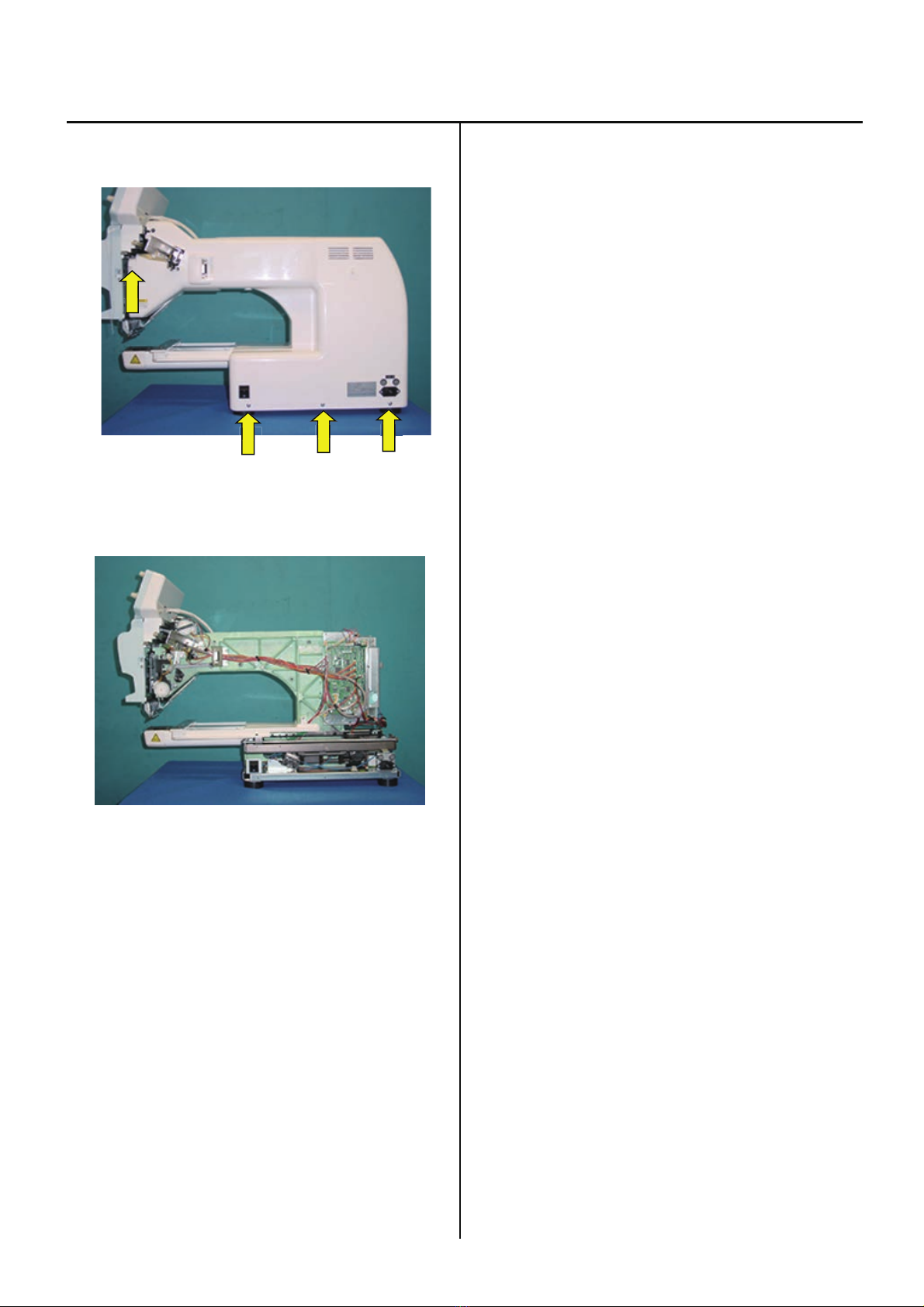
Removal of outer covers (CONTROL BOX) 2-1
<Check> Be sure to turn power switch OFF before
work.
1. Remove three setscrews of arm E as shown in the
figure
below.
2. Disconnect the connectors indicated by the arrows in
the figure below. Remove the screw that fixes cables.
3. Remove two screws on arm D as shown in the figure
below.
4. Remove control box.
15
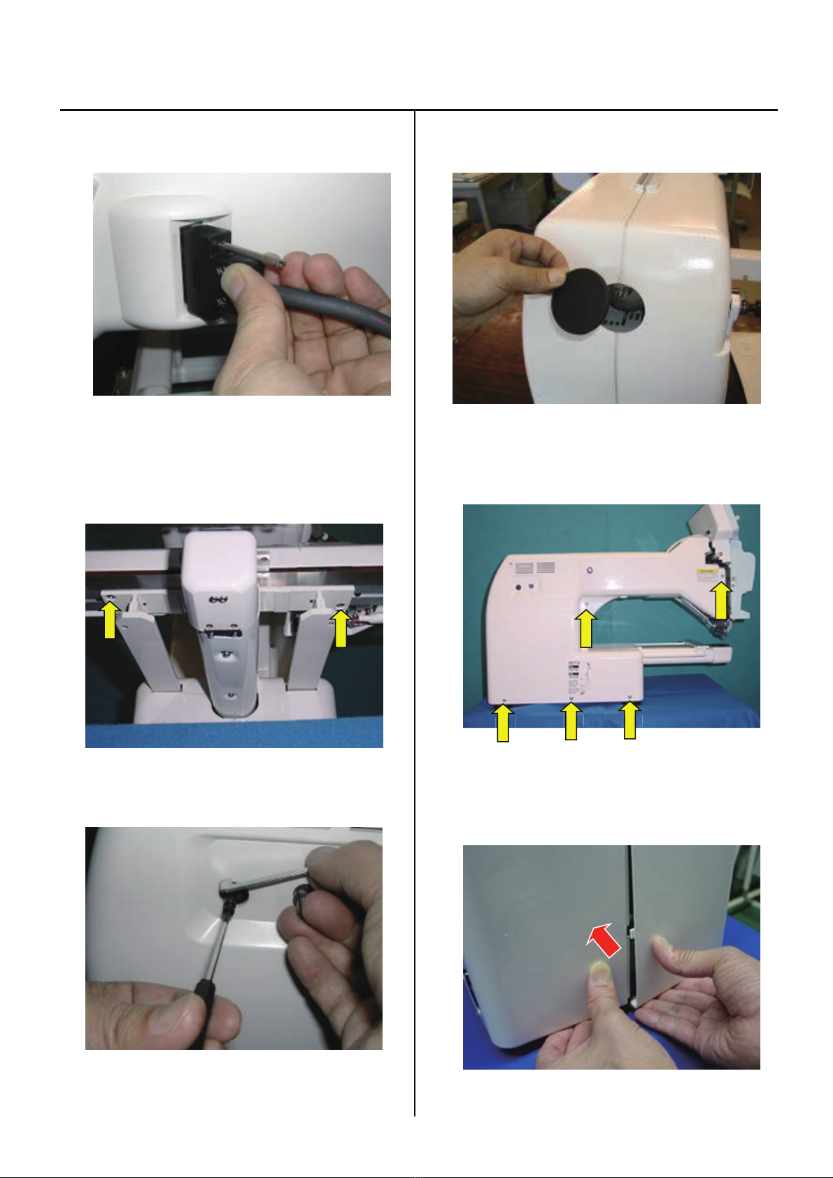
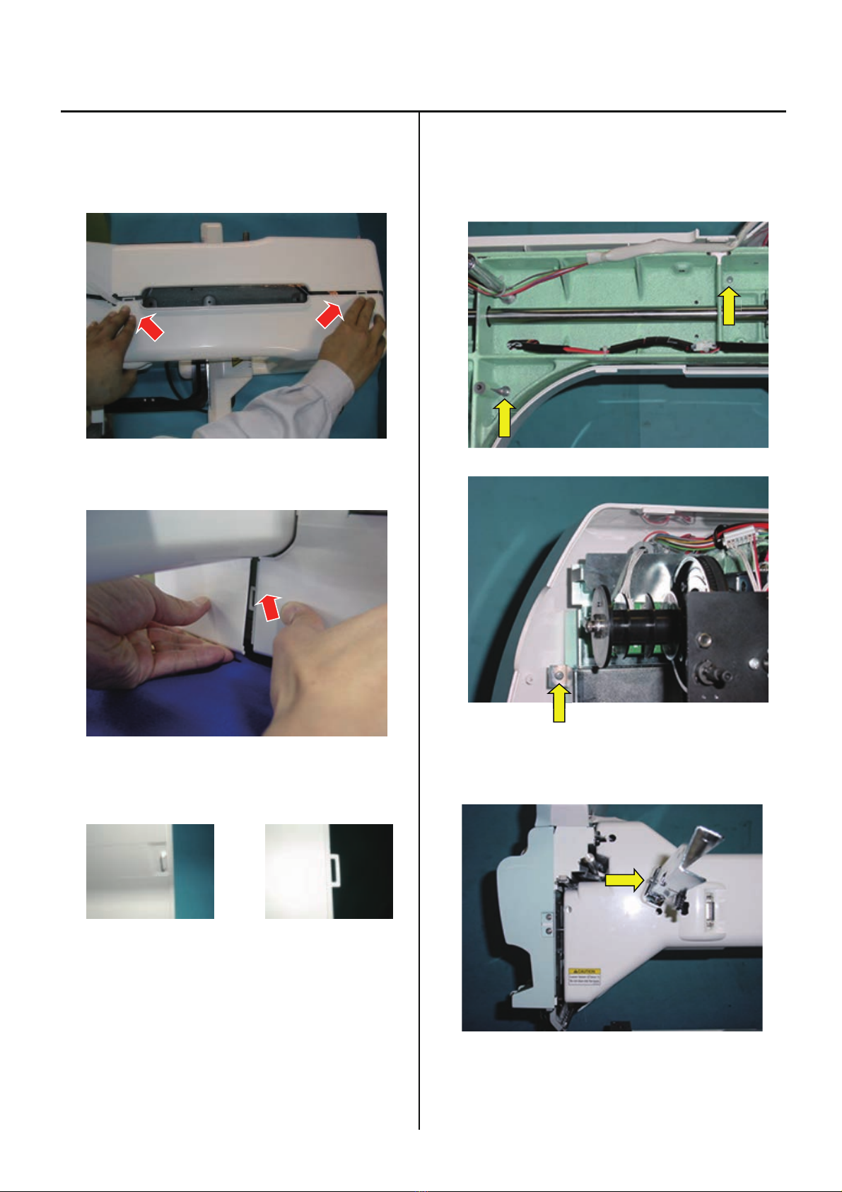
Removal of outer covers 2-1
5. Disconnect cable for X carriage.
6. Remove 2 screws, then take the X carriage off.
7. Remove the guide.
8. Take off rubber cap.
9. Remove cover (left). (Remove screw in arrow mark)
10. Unlock nail of the cover (left) by pressing an arrow point of
the cover (right).
x
x
x
16
Removal of outer covers 2-1
11. Remove the cover by pressing an arrow part of
the picture.
(1) Upper part of the cover
(2) Front part of the cover
Nail shape
Male nail shape Female nail shape
12. Remove the screw of an arrow part of the
picture which fixes cover (right).
13. Remove an arrow marked screw which fixes hold arm D.
x
17
Removal of outer covers 2-1
14.Remove cover (light). (Remove screw in arrow mark)
15. Remove the cover (right).
16.By above process, removal of [cover] has finished.
If you need to operate the machine with control box,
please re-assemble the arm and the control box.
x
18
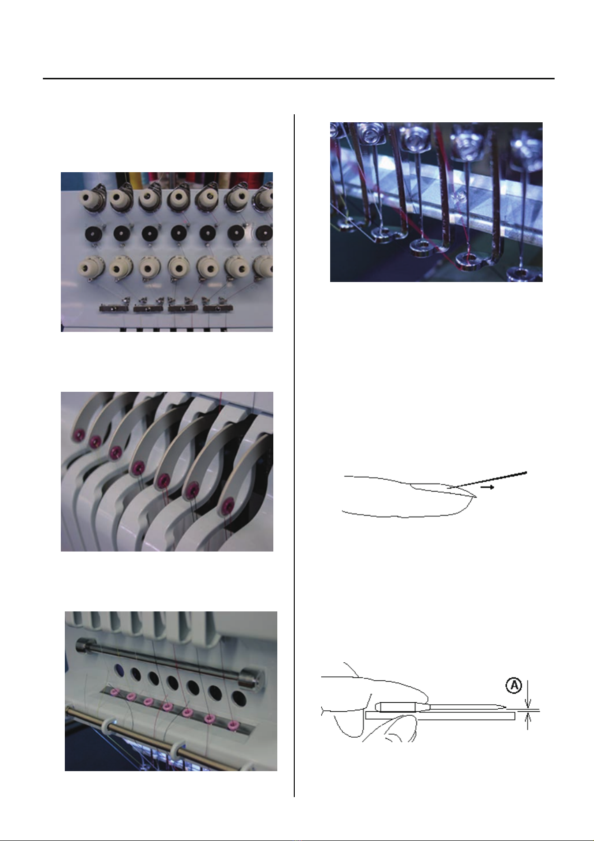
Maintenance of thread path 3-1-1
In a bid to prevent poor sewing finish or thread break, please keep places where thread contacts in the best condition.
1. Thread tension, detecting roller
a) Revolution must be smooth
b) No sticking of lint or dust
2. Ceramic and rim of take-up lever
a) No burr and crack
3. Thread path in lower side and needle holder.
a) No burr and crack
4. Needle
a) Needle tip shouldn't be warped or bent.
When you slide needle tip on surface of nail and
if the nail gets scratched.
needle tip is warped. Please exchange it with new one.
Please place needle on flat surface and check
clearance (A) from side.
If clearance is not equal, needle is bent.
Please replace it with new one.

19
Maintenance of thread path 3-1-1
5. Needle plate
a)No burr and crack in needle hole and around it.
6. Pressure foot
a) No burr and crack inside hole
b) Not bent
7. Rotary hook
a) No burr and crack.
b) Hook point not warped.
c) Backlash between bobbin case holder and outer hook
should be less.
8. Keeper
a) No burr and crack on tip.
Surface
Reverse side

20
Fixing of needle 3-1-2
1. In order of (1)-(4), please remove and fix needle.
(1) Loosen screw holding needle.
(2) Remove needle.
(3) Insert needle till it goes to the end.
(4) Tighten screw holding needle.
Fix needle so that needle groove faces front.
Needle holder
Needle
Front
①④
③②
Table of contents
Other HappyJapan Sewing Machine manuals


 User manual")


