Ricoma 8S User manual

8S computerized Embroidery Machine Operation Manual V2.0
I

8S computerized Embroidery Machine Operation Manual V2.0
II
CONTENTS
PART 1 CONTROL SYSTEM INTRODUCTION.........................................1
1.1 SYSTEM OVERVIEW......................................................................................................... 1
1.2 PRECAUTIONS .................................................................................................................. 1
1.3WORKING ENVIRONMENT............................................................................................... 2
1.4 SYSTEM POWER SUPPLYAND EARTHING........................................................................ 2
1.5 OPERATION PANELAND KEY FUNCTION INTRODUCTION .............................................. 3
1.5-1 Key Function Introduction.....................................................................................................3
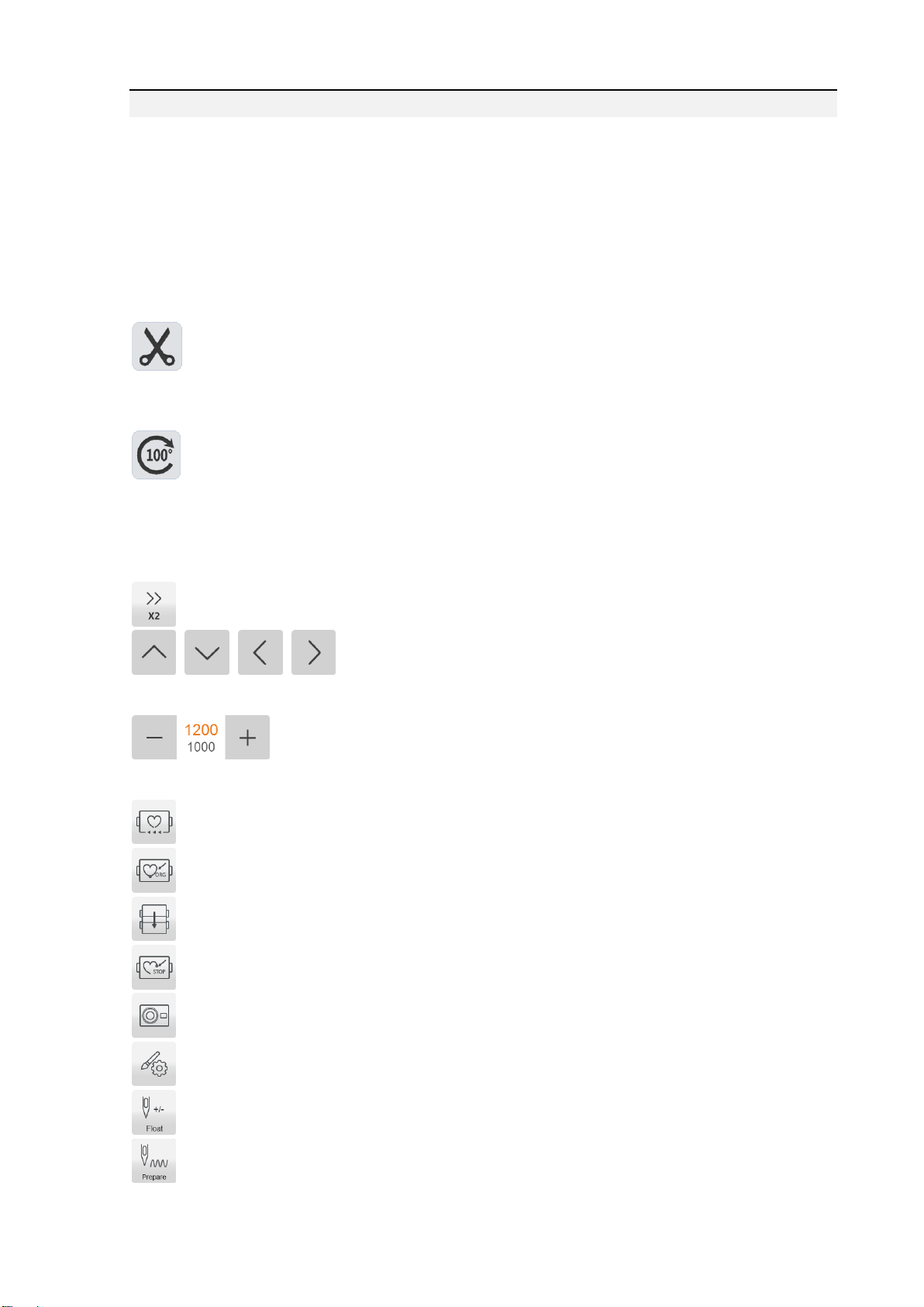
1.5-2 Icons Description of Touch Keys................................................................................................3
1.5-3 Function Introduction.................................................................................................................4
PART 2 EMBROIDERY CARD INPUT OPERATION ................................6
INPUT U-DISK EMBROIDERY CARD TO MEMORY................................................................. 6
PART 3 EMBROIDERY CARD MANAGEMENT........................................8
3.1 SELECT EMBROIDERY CARD FOR EMBROIDERING ........................................................ 8
3.2 DELETE SINGLE EMBROIDERY CARD ............................................................................. 9
3.2 OUTPUT EMBROIDERY CARD TO U-DISK ........................................................................ 9
PART 4 EMBROIDERY CARD .....................................................................10
4.1 EMBROIDERY STATUS SWITCHING................................................................................ 10
4.2 PREPARATION STATUS ....................................................................................................11
4.2-1 Set Embroidery Card Parameters...........................................................................................11
4.2-2 Switch Tabouret.........................................................................................................................13
4.3WORKING STATUS.......................................................................................................... 14
4.3-1 Embroidery Card Origin (Starting Point) Setting..................................................................14
4.3-2 Camera positioning (only for machines with this feature).....................................................16
4.3-3 Offset Point (Highest Point of Tabouret Center) Setting.......................................................16
4.3-4 Return to Origin (Starting Point).............................................................................................16
4.3-5 In and Out Tabouret Operation...............................................................................................16
4.3-6 Return to Stop Point..................................................................................................................17
4.3-7 Set Color Changing...................................................................................................................17
4.3-7-1 Set Color Changing Sequences .............................................................................................18
4.3-7-2Applique Offset, Low Speed Embroidering and Needle Bar Replacement.......................19
4.3-8 Embroidering Mode Switching................................................................................................20
4.3-9 Float............................................................................................................................................21
4.3-10 Operation of Returning to Embroidering Point in Power Failure......................................21
4.4 EMBROIDERY RUNNING STATUS.................................................................................... 22
4.5 BAR DRAWING OPERATION ........................................................................................... 22

8S computerized Embroidery Machine Operation Manual V2.0
III
PART 5 LETTERS TO GENERATE EMBROIDERY CARD...................23
PART 6 MANUAL OPERATION FOR COLOR CHANGING..................25
PART 7 MANUAL TRIMMING.....................................................................26
PART 8 TABOURET ORIGIN OPERATION..............................................27
8.1 MANUAL TABOURET ORIGIN SETTING..........................................................................27
8.2AUTOMATIC SEARCHING FOR ABSOLUTE ORIGIN OF TABOURET.................................27
PART 10 REPORT...........................................................................................29
PART 11 SPINDLE JOGGING OPERATION.............................................30
PART 12 LANGUAGE SWITCHING............................................................31
PART 13 EMBROIDERY PARAMETERS...................................................32
PART 14 MACHINE PARAMETERS SETTING........................................33
PART 15 USER MANAGEMENT..................................................................34
15.1 TIME SETTING...................................................................................................................34
15.2 UNFREEZE .........................................................................................................................35
PART 16 SYSTEM TEST................................................................................36
16.1 INPUT TEST...................................................................................................................36
16.2 OUTPUT TEST ...............................................................................................................36
16.3 SPINDLE TEST...............................................................................................................37
16.4 MACHINE HEAD TEST (USED ONLY IN ORGANIC HEAD PANELS).................................38
PART 17 SYSTEM INFORMATION ............................................................39
17.1 SYSTEM NUMBER AND VERSION INFORMATION CHECKING.......................................39
17.2 LOGO UPDATE ..............................................................................................................39
17.3 INTERFACE UPDATE .....................................................................................................40
17.4 SOFTWARE UPDATE......................................................................................................40
PART 18 NETWORK SETTING....................................................................41

8S computerized Embroidery Machine Operation Manual V2.0
IV
PART 19 APPENDIX .......................................................................................42
19. 1PARAMETER TABLE..................................................................................................... 42
19. 2SYSTEM ERRORS AND COUNTERMEASURES LIST ...................................................... 45

8S computerized Embroidery Machine Operation Manual V2.0
1
Part 1 Control System Introduction
1.1 System Overview
Thank you for using computer embroidery machine control system of our company!
The system can be collaborated with various kinds of embroidery machines for using to
satisfy different requirements of embroidery. It has satisfactory effects for thin material,
thick material and three-dimensional embroidery!
Advanced RAM + DSP dual-CPU control technology, Make the system faster, can
multi-task operation, in the embroidery can transfer files and other operations., and enables
the mechanical operation more stabled. Additionally, it reduces noise of complete machine
and prolongs mechanical service life!
Before using the machine, please read the operation manual carefully to ensure correct
using of the system.
Please keep the operation manual properly for easy reference.
As configuration varies, some machines do not have partial function listed in the manual.
Details of corresponding operation function shall prevail.
1.2 Precautions
Please don’t take maintenance and commissioning for electrical system by
non-professional personnel, which may reduce safety performance f equipments, enlarge
accident, or even cause personnel injury and property loss.
Some parts in the case may have high voltage. After powering on the system, please don’t
open the case cover to avoid causing accidental injury.
Please replace protective tube according to the product identification requirements strictly
to ensure personnel and property safety.
Power switch of the product has over-current protection function. If over-current
protection switch is actuated, it must be closed again after 3 minutes.
Please don’t pile up debris around the control cabinet. During using process, clean the

8S computerized Embroidery Machine Operation Manual V2.0
2
surface of control cabinet and dust on filter regularly to ensure good ventilation of system and
be conductive for heat radiation.
Without authorization of the company, please don’t modify the products. Otherwise, the
company undertakes no liability for the caused results!
Warning
When it is necessary to open the case cover, it can only permit to touch the parts in the
electrical cabinet under the guidance of professional personnel after 5 minutes.
Prohibition
When the machine is in operation, it is prohibit touching any moving part or opening
control equipment. Otherwise, it may cause personnel injury or cause abnormal operation of
machine.
It is prohibit operating electrical equipments in working environment with moisture, dust,
corrosive gases and flammable and explosive gases. Otherwise, it may cause electric shock or
fire.
1.3 Working Environment
Good ventilation, healthy environment, less dust;
Working space temperature: 5-40 °;
Working Space Relative Humidity: 30% -90% non-condensing
1.4 System Power Supply and Earthing
The electric control system can use the following power:
Single phase AC100-240V/50-60HZ
According to different machine configuration, power consumption is between 0.1-0.4KW.
To prevent electrical equipment from causing electric shock or fire accidents due to
electric leakage, over-current, insulation and other causes, please earth the electric
control reliably.
Earthing resistance shall be less than 100 ohm, conductor length shall be within 20m and

8S computerized Embroidery Machine Operation Manual V2.0
3
conductor cross-section shall be greater than 1.0 mm2.
1.5 Operation Panel and Key Function Introduction
1.5-1 Key Function Introduction
Manual trimming key: take manual trimming in operation status and preparation
status.
Spindle jogging key: Press the key and job the spindle to 100 degree.
1.5-2 Icons Description of Touch Keys
Selection key: Used to select frameshift and lifting spindle speed.
Up, down, left and right keys: Move tabouret in embroidery card
and preparation status.
Lifting spindle speed key: - key for deceleration, and + key for
acceleration.
Set the start point and walk the surrounding of pattern.
Origin operation key
Offset point operation key
Returning to stop point key
Camera key, in a camera function, open the camera to adjust the flower version
Embroidery parameter setting
Empty go key, press color or press the stitch forward and backward
Embroidering way switching key (normally embroidering)

8S computerized Embroidery Machine Operation Manual V2.0
4
Manual color changing key, left side displays current needle position and right side
displays spindle degree.
Report key
Setting key
Back key
OK key
LED lighting switch
Embroidery status swithcing key
Select pattern embroidery and input embroidery card
Color changing setting key, left side displays current color needle bar and
additional settings, and right side displays next needle bar and additional settings.
Toggles the frame and switches the desired frame in the ready state
Set related parameters of patterns, and it can only operate embroidery under
embroidery preparation status.
AX/AY: Display relative origin coordinates of embroidery card.
PX/PY: Display absolute origin coordinates of embroidery card.
Start key indicators: Readiness long red light, work status long bright green, red flashing
break, mending color.
1.5-3 Function Introduction
The system has a friendly HMI operation mode. It is easy to be operated and learned. The
system has powerful functions and is greatly convenient for user using. It has improved
operational performance and efficiency.

8S computerized Embroidery Machine Operation Manual V2.0
5
With multilingual support, it can switch the operation system language based on the
user’s needs at all times.
With large memory capacity, the system can store 20 million stitches and 200 embroidery
cards.
With multiple embroidery card input paths, it is extremely convenient for client’s
selection and using, such as Mobile U disk, network (PC software required).
The system supports multiple embroidery card file formats and can identify Tajima DST
and Barudan DSB and so on.
Powerful parameter adjustment function can adjust various parameters according to the
requirements in order to meet the required system control performance.
Automatic embroidery recovery function in power failure can recover to previous several
stitches and continue embroidering automatically after there is a sudden power failure in
embroidering process without having to worry about misplacement of embroidery card, to be
free from complex re-alignment operation.
Equipment self-test function can take detection for the state of electrical equipment and
parameters for convenient adjustment and maintenance.
For spindle stop position adjustment function, the user can take system parameter
adjustment according to the features of respective embroidery machine to achieve accurate
stop position.
Automatic embroidery card parameter memory function may take automatic saving for
the set embroidery parameters or related data of embroidered card, including color changing,
origin, offset point, embroidery parameter, repetition and other information for the
convenience of using the same embroidery card.
Appliquéoffset function can set any color changing bar and take appliquéout of frame
for convenient appliquéoperation.
Accurate flower version Near and embroidery capabilities to meet you for taking the plate
positioning and embroidery needs.

8S computerized Embroidery Machine Operation Manual V2.0
6
Part 2 Embroidery Card Input Operation
Embroidery card input operation is to input embroidery card in U disk into memory. It
can be operated at embroidery preparation status and embroidery card status.
Embroidery card input is to input files on external storage medium into system memory
for convenient embroidery selection. If there is no embroidery card in memory, it will enter
into the interface when the system is started.
The system supports reading Tajima DST and Behringer DSB formats of embroidery
card files.
Before reading the embroider card, insert the U disk into USB interface, and then take
operation panel key operation.
Input U-disk Embroidery Card to Memory
After U disk us inserted, press key to enter into embroidery card
management interface. It will read the contents in U disk, as in the following Fig.
When embroidery card interface is selected, pres key to switch to U
disk interface.

8S computerized Embroidery Machine Operation Manual V2.0
7
Click to enter the flower version, a preview of the currently selected file is displayed
below the currently selected flower version of pin number, color, size and other relevant
information and thumbnails. Press key to save in the memory. Input speed is popped
up automatically to display memory number and input speed. After input is completed, it
returns to U-disk operation interface automatically and it can continue taking input operation.
If it enters into subdirectory of U disk, press key to return to previous
interface.
Press key to return to main interface.

8S computerized Embroidery Machine Operation Manual V2.0
8
Part 3 Embroidery Card Management
In main interface, press key to enter into embroidery card management
interface, as in the following Fig:
If it is in U disk interface, press key to enter into embroidery card
management interface.
3.1 Select Embroidery Card for Embroidering
Click embroidery card for embroidery. Currently selected stitch number, color, size and
other related information and thumbnail are displayed on the right side. Press key
to skip to embroidery card parameter setting interface automatically.
If it is still in embroidery card status, it cannot select embroidery card, and related
prompt information is popped out.
Press key to return to main interface.

8S computerized Embroidery Machine Operation Manual V2.0
9
3.2 Delete Single Embroidery Card
In embroidery card management interface, press key to enter into single deletion
operation.
3.2 Output Embroidery Card to U-disk
In embroidery card management interface, select embroidery card to input. Click
key to input into U disk.
Upper value in means current page, and lower value measn max
pages of current embroidery card number. Left and right keys can take page turning. However,
max page turning value cannot be larger than max pages of currebt embroidery card.

8S computerized Embroidery Machine Operation Manual V2.0
10
Part 4 Embroidery Card
4.1 Embroidery Status Switching
It has 3 embroidery statuses, i.e. preparation status, working status and running status. It
can take status switching via keys on interface. It enters into running status after drawing the
rod to start embroidering, as in the following Fig.
Preparation Status
In preparation status, press key, and pop up “Into Embroidering Status or
Not”. Press key to enter into working status, as in the following Fig.

8S computerized Embroidery Machine Operation Manual V2.0
11
Working Status
In working status, press key and pop up “Release embroidery status or not”.
Press key to enter into preparation status.
4.2 Preparation Status
In preparation status, it can take spindle jogging, trimming, tabouret switching, manual
color changing, embroidery card parameter setting and embroidery card selection and other
operation.
4.2-1 Set Embroidery Card Parameters
In preparation status, press key and take embroidery card parameter setting
operation, as in the following Fig.

8S computerized Embroidery Machine Operation Manual V2.0
12
Modify values according to the embroidery. After modification is completed, press
key to save modification. Press key to return to main interface.
Parameter Range Description:
Rotation directions: totally 8, i.e. default 0°, 90°, 180°, 270°, 0°mirror, 90°mirror,
180°mirror and 270°mirror
Rotation angle: 0-89°(the angle is calculated after rotation direction)
X/Y direction multiplying power: 50%-200%
X/Y replication number: 1-99
X/Y direction space: 0-±999.9mm
The control system takes mm as unit. It is input in 0.1mm when inputting digits, i.e. it
shall input 1000 when inputting 100mm.
X/Y compensation (satin stitch): 0-±0.3

8S computerized Embroidery Machine Operation Manual V2.0
13
4.2-2 Switch Tabouret
In embroidery card parameter setting interface, press the input box behind
to enter into tabouret switching operation, as in the following Fig.
Select current embroidery used taboure type. Press key When hat frame and
A-G taboures are selected, the taboure will search absolute origin automatically, and stop at
center of selected taboure. Please pay attention to the taboure movement.
See Taboure Setting on embroidery range of hat frame andA-G taboures
Other taboures don’t take absolute origin searching. Embroidery range is also confirmed
by software limits setting (See Software Limits Setting on detailed operation).
Select interface behind taboure and return to preparation status automatically. If taboure
type is not selected, the system will continue to use previously used taboure type
automatically.
After hat frame is selected for using, currently selected embroidery card will be rotated
180°automatically, and other taboures are not changed.

8S computerized Embroidery Machine Operation Manual V2.0
14
Edit hoop
If you need to modify the frame size, press the key to set.。
Set tabouret related parameters according to the requirements. After setting is completed,
press key to save setting.
Tabouret Setting Diagram:
X Si ze
YSi ze
Space Or ig i n
XCen t e r si z e
YCenter size
Fra m e ce n t e r
4.3 Working Status
In working status, it can take embroidery card origin (starting point) setting, embroidery
card origin returning, offset point returning, stop point returning, color changing sequences
setting, spindle jogging, manual trimming, working mode changing, embroidering mode
switching, embroidery card contour, embroidery range checking and embroidering point
returning operation in power failure.
4.3-1 Embroidery Card Origin (Starting Point) Setting
In working status, move the taboure to required embroidery card origin (starting point).
Press key to take origin setting. If the current version of the embroidery in the middle,
will pop up a prompt box. Operate as needed.The taboure walks along the max range of
embroidery card. If the position is insufficient, it modifies the origin (starting point)

8S computerized Embroidery Machine Operation Manual V2.0
15
automatically. After being modified, it prompts error if the position is still insufficient. After
the origin (starting point) is positioned, AX/AY coordinates are clear. Figure:
Press to return to the main interface.
After the embroidery card origin is set, if empty stitches embroidery card contour and
embroidering embroidery card contour are required, it can use the operation.
The operation is only operated after setting embroidery card origin and before taking bar
drawing. It cannot be operated after the bar drawing.
Empty stitches card contour
After setting start point and searching embroidery card contour, press key and the
tabouret is started idling from start point along the contour (precise range). After idling is
finished, it returns to start point automatically.
Embroidering card contour
After setting start point and searching embroidery card contour, press key and
the tabouret is started embroidering contour from the start point and along the pattern
surrounding. After embroidering is finished, it returns to start point automatically.

8S computerized Embroidery Machine Operation Manual V2.0
16
4.3-2 Camera positioning (only for machines with this feature)
Camera positioning is mainly to facilitate the use of embroidery materials.
In the work interface, press the key to open the camera, shift the embroidery
material on the cross of the center point and the cross on the center of the screen, the
key rotation of the cross and cross the material on the cross, the
button to save the rotation settings. Flower version of the file rotation.
4.3-3 Offset Point (Highest Point of Tabouret Center) Setting
Offset point is mainly for conveniently embroidery material drawing and releasing and
applique placement.
In “Other Parameters” of “Embroidery Parameters”, set “Automatic offset out of taboure’
as “Yes”. After it is set properly, the taboure returns to embroidery card origin to start
embroidering after start-up every time. After the embroidery is completed, it is out of the
taboure and stops at the offset point.
Offset out of the taboure depends on the set dimensions of taboure, and it is deviated to
the highest position of currently selected taboure automatically.
4.3-4 Return to Origin (Starting Point)
In the embroidering process, if it is required returning to the origin to re-start the
embroidering, it can take the operation.
Pres key and the system will pop up “Terminate embroidering and return to the
origin?”Press key and the taboure is moved to the embroidery card origin and
stop. AX/AY coordinates are cleared.
4.3-5 In and Out Tabouret Operation
In the embroidering process, if is required returning to the offset point, it can take the
Table of contents
Other Ricoma Sewing Machine manuals

Ricoma
Ricoma RCM-1201PT User manual

Ricoma
Ricoma RCM 1501 PT User manual

Ricoma
Ricoma CHT2 User manual

Ricoma
Ricoma MT-1502 User manual

Ricoma
Ricoma EM-1010 User manual

Ricoma
Ricoma TCS1501 User manual

Ricoma
Ricoma EM-1010 User manual

Ricoma
Ricoma SWD Series User manual

Ricoma
Ricoma RCM-1201TC-7S User manual

Ricoma
Ricoma EM-1010 User manual