HappyJapan HCR3E Series User manual

3EVB10-13
HCR3E
Industrial Multi-head Embroidery Machine
INSTRUCTION BOOK
Program Ver. C.3.04~


-3A -3
CONTENTS
IMPORTANT SAFETY INSTRUCTIONS... 1-1
WARNING LABELS & THEIR LOCATIONS
..... 1-2
SETTING UP THE MACHINE
Connection to power source ................... 2-1
Disposal of a battery ............................... 2-1
Assemble machine unit........................... 2-2
Machine installation ................................ 2-3
Assemble of removable table and border frame
.... 2-6
Removing of removable table and border frame
. 2-6b
Center support ........................................ 2-7
Assemble bobbin winder (Option)........... 2-8
MAIN PARTS............................................. 3-1
THE CONTROL BOX ................................ 3-3
DRIVE MODE.................................. 3-4
Frame change......................................... 3-8a
MENU................................................... 3-A
INSERTING A NEEDLE............................. 4-1
SELECT NEEDLES AND THREADS ....... 4-2
BACKING MATERIALS ............................. 4-3
BORDER FRAME CLIP............................. 4-3a
BOBBIN WINDING
Winding the bobbin (Option) ................... 4-4
Removing the bobbin.............................. 4-5
Inserting the bobbin ................................ 4-5
Adjusting bobbin thread tension.............. 4-5
Inserting the bobbin case........................ 4-5
THREADING THE MACHINE
How to thread upper thread .................... 4-6
HOW TO READ THESE INSTRUCTIONS, SCROLLBAR
... 4-8
DISPLAYING THE PATTERN IN SETTING MODE
... 4-9
TURNING THE MACHINE ON
How to turn on the machine.................... 5-1
How to turn off the machine.................... 5-1c
Calendar and clock setting...................... 5-2
MESSAGES .............................................. 5-3
PREPARATION OF PATTERN DATA
Connecting to a PC................................. 5-4
Reading embroidery pattern data from the PC
. 5-4b
Reading embroidery pattern data ........... 5-5
Selection of folders ................................. 5-9
How to select patterns from memory ... 5-A
Erasing patterns from memory.............. 5-B
NEEDLE BAR SELECTION .................... 5--E
SEWING WITH TUBULAR FRAMES
Installing and removing the tubular frame
bracket .................................................... 6-1
How to hoop............................................ 6-2
Mounting the hoop on the machine......... 6-3
Cloth guard
(For provided with middle carriage)
.....................
6-3
Starting to embroider .............................. 6-4
CAP FRAME (option)
Cap frame settings.................................. 7-1
Installing and removing the cap drive frame...
7-2
Normal cap frames.................................. 7-5
Wide cap frames..................................... 7-8
Starting to embroider ........................... 7-B
ADJUSTING THE THREAD TENSION ..... 8-1
ADJUSTING THE LASER POINTER (OPTION)
.. 8-2
BORER (Option)........................................ 8-4
SEWING
What to do if the thread breaks while sewing
9-1
Stopping and resuming sewing............... 9-1
Loss of power while embroidering .......... 9-2
Moving the hoop while embroidering and then returning to
the correct location (Position)
............................. 9-3
Moving back to the starting point
(Origin)
9-3
Going back to the beginning of the design (Top)
... 9-4
Placing the design in the center of the selected
embroidery frame
(Center)
........................... 9-4
Rotating and mirroring designs (Convert)
..... 9-5
Starting in the middle of a design (Position) ...
9-6
Mending the faulty part of embroidery
(Mending).......................................... 9-7b
POSITION ALIGNMENT BY DEFINING 2 POINTS
.. 9-8
POSITION ................................................. 9-B
Piece number..........................................9-C
Bobbin thread alarm..............................9-Ca
Work save .............................................9-Ce
REGISTER ................................................9-D
Entry........................................................9-E
Return .....................................................9-F
READING
Join ....................................................... 10-1
Pattern read settings............................. 10-3
0_1 TA01
0-1

-3A -4
CONTENTS
0_2 V601
0-2
PATTERNS IN MEMORY
Locking pattern data ..............................11-1
Trace type ..............................................11-2
Export.....................................................11-3
Renaming patterns.................................11-5
Copying pattern data..............................11-6
Moving pattern data ...............................11-7
Renaming folders...................................11-9
Sort ........................................................11-A
Thread break report .............................. 11-B
Retrieve built-in data from machine ......11-C
Searching pattern data..........................11-D
NEEDLE BAR SELECTION .................... 12-1
Auto setting........................................... 12-2
Thread color.......................................... 12-4
Color change data registration.............. 12-6
Color change data read ........................ 12-7
Repetition of color group setting ........... 12-8
FRAME CONFIRMATION ....................... 13-1
Frame selection
....................................... 13-2
Adjusted for embroidery area................ 13-4
User-dened frames (1 ~ 5).................. 13-7
User-dened frames (6 ~ 20).................13-A
How to change center point of frame (1 ~ 5, 6 ~ 20) ........
13-H
Non registered frame .............................13-J
PATTERN SETTINGS ............................. 14-1
Scaling .................................................. 14-2
Width adjustment .................................. 14-3
Angle..................................................... 14-4
Repeat sewing ...................................... 14-5
Auto origin............................................. 14-7
Offset .................................................... 14-8
Frame out...............................................14-D
MACHINE SETTINGS............................. 15-1
LOCK STITCHES.................................... 15-5
OPTIONAL DEVICE SETTING ............... 15-6
LETTER................................................... 16-1
QUEUE.................................................... 17-1
How to make design data for continuous embroidery
.. 17-1c
Alter and Execution (Standard Mode)... 17-2
Alter and Execution (Continuous Mode)
.. 17-3b
Needle bar selection and Pattern settings
... 17-4
Registration of QUEUE setting ............. 17-6
Read QUEUE setting............................ 17-7
OTHER SETTINGS
Create network...................................... 18-1
Wire LAN connection setting .....................18-2b
Wireless LAN connection settings (Option)
...18-2e
Version information and software update
.... 18-3
Language.............................................. 18-5
Calibrate................................................ 18-6
User maintenance mode....................... 18-8
Report...................................................... 19-1
GUIDE .................................................. 20-1
SCREEN SAVER..................................... 21-1
i-CUSTOM............................................... 22-1
LAN connection .........................................22-2b
TASK RESERVATION ............................... 22-2c
Reading................................................. 22-2d
Needle bar selection ............................. 22-2e
Setting................................................... 22-2f
Search................................................... 22-2g
List ........................................................ 22-2h
Letter..................................................... 22-2i
Layout ................................................... 22-2j
USER MANAGEMENT
Registration of administrator................. 22-3
Registration of user............................... 22-6
Selection of user (Login) ....................... 22-8
Selection of user (Login) at power ON.. 22-9
LAYOUT ...................................................22-A
THREAD SET...........................................22-K
SPECIFICATIONS .................................. 23-1
MAINTENANCE
Oiling..................................................... 23-1b
Cleaning the rotary hook
Cleaning the thread cutting knife .......... 23-2
ERRORS AND WHAT TO DO ................. 24-1
INITIALIZING OF MACHINE SETTINGS
Re-Initialization of machine system,
Initialize the PMS, Initialize the Network.. 25-1
Initializing of machine speed................. 25-2
HELPFUL HINTS..................................... 26-1
EMBROIDERY TERMS........................... 26-2
BUILT-IN FONT LIST............................... 26-3
BUILT-IN PATTERNS LIST...................... 26-4
VARIOUS SPECIAL FRAMES (OPTIONS)
.... 27-1

-CR -5
IMPORTANT SAFETY INSTRUCTIONS
1_1 H901
1-1
When using an electrical appliance, basic safety precautions should always be followed,
including the following.
Read all instructions before using this appliance.
DANGER - To reduce the risk of electric shock:
1. An appliance should never be left unattended when plugged in. Always unplug this appliance
from the electric outlet or switch main breaker OFF after using and before cleaning.
WARNING
- To reduce the risk of burns, fire, electric shock, or injury to persons:
1. Do not allow to be used as a toy. Close attention is necessary when this appliance is used
by or near children.
2. Use this appliance only for its intended use as described in this manual. Use only
attachments recommended by the manufacturer as contained in this manual.
3. Never operate this appliance if it has a damaged cord or plug, if it is not working properly, if it
has been dropped or damaged, or dropped into water. Return the appliance to the nearest
authorized dealer or service center for examination, repair, electrical or mechanical
adjustment.
4. Never operate the appliance with any air openings blocked. Keep ventilation openings of the
sewing machine free from the accumulation of lint, dust, and loose cloth.
5. Never drop or insert any object into any opening.
6. Do not use outdoors.
7. Do not operate where aerosol (spray) products are being used or where oxygen is being
administered.
8. To disconnect, turn all controls to the off (“0”) position, then remove plug from outlet.
9. Do not unplug by pulling on cord. To unplug, grasp the plug, not the cord.
10.Keep fingers away from all moving parts. Special care is required around the sewing
machine needle.
11.Always use the proper needle plate. The wrong plate can cause the needle to break.
12.Do not use bent needles.
13.Do not pull or push fabric while stitching. It may deflect the needle causing it to break.
14.Switch the sewing machine off (“0”) when making any adjustments in the needle area, such
as threading needle, changing needle, threading bobbin, or changing presser foot, etc.
15.Always unplug this appliance from the electric outlet or switch main breaker OFF when
removing covers, lubricating, or when making any other user servicing adjustments
mentioned in the instruction manual.
SAVE THESE INSTRUCTIONS
-CR -5
WARNING LABELS & THEIR LOCATIONS
1_2 H901
1-2
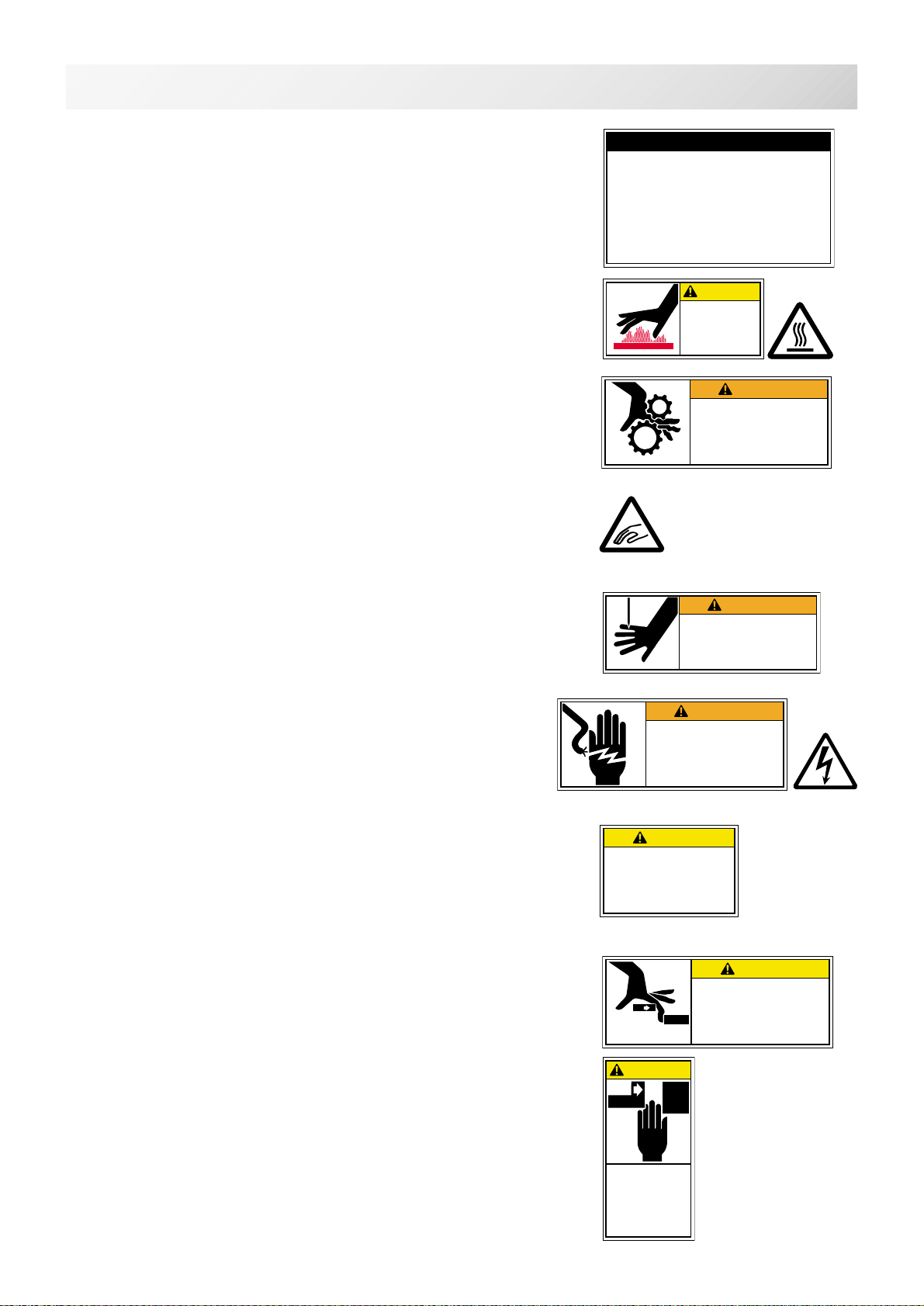
Safety Instruction Sticker for servicing, operating and
maintaining
Caution Sticker for hot surface
( on all pulse motors, the motors may reach a certain temperature after
long time running, which can reach up to 60°(C )
Risk of serious finger and hand injury
Please make sure this cover is always closed and fixed via screw, only
for necessary action you are allowed to open it, never leave it open
while machine is running.( please see sketch for location )
Trapping hazard wherever this label is found
Injury risk warning for all needles
Keep fingers away from the needles while the machine is running.
Shock hazard on all electrical components
All works on electrical power cabinet must be carried out by
authorized and qualified Personnel.
Trapping hazard on all moving heads,
due to avoid additional stress for operator we did not cover this area,
because for each time the string is broken it would necessary to
remove it;
Please consult our local sales department and we will seek a solution.
CAUTION sticker for trapping hazard EN 292,
Please read carefully the instructions on this sticker
(the sticker may vary for production reason)
ES-HMF-5113-0
WARNING
Shut the cover when starting the
machine. Do not put hands in
while the machine is running.
Fear of serious injury.
ES-HMF-5112-1
Fear of serious injury.
Keep fingers away from
the needles while
the machine is running.
WARNING
ES-HMF-5117-0
CAUTION
Keep hands away from the
moving heads while the
machine is running.
Possibility of injury.
ES-HMF-5127-0
SAFETY INSTRUCTIONS
1. Machine must be operated by well trained
person only.
2. Machine must be used for original purpose
only, do not use for other purpose.
3. Shut machine off to oil, adjust or service.
4. Do not operate machine fill close and fix
cover.
5. Do not leave running when unattende.
ES-HMF-5128-0
Do not touch
hot surfaces.
CAUTION
ES-HMF-5116-1
WARNING
Fear of electric shock,
burns or death.
Only authorized repairman can
open the cover.
ES-HMF-5114-0
CAUTION
Possibility
of injury.
Keep hands away
from the drive
frame while
the machine
is running.
ES-HCM-5108-0
Possibility of injury.
Keep hands away from
the drive frame while
the machine is running.
CAUTION

-CR -6
WARNING LABELS & THEIR LOCATIONS
1_3 H901
1-3
Laser beam (Class 1)
CAUTION
Do not stare into the beam.
ES-HMF-5115-0
CAUTION
Possibility
of injury.
Do not put fingers
in holes or grooves
of the table.
All grooves are minimized to 8 mm,
so that fingers may not enter, however it depends on various
circumstances, the manufacturer can not foreseen.
Laser beam (Class 1)
Do not stare into the beam.
-3A -8
SETTING UP THE MACHINE
for qualified personnel only
2_1 V617
2-1
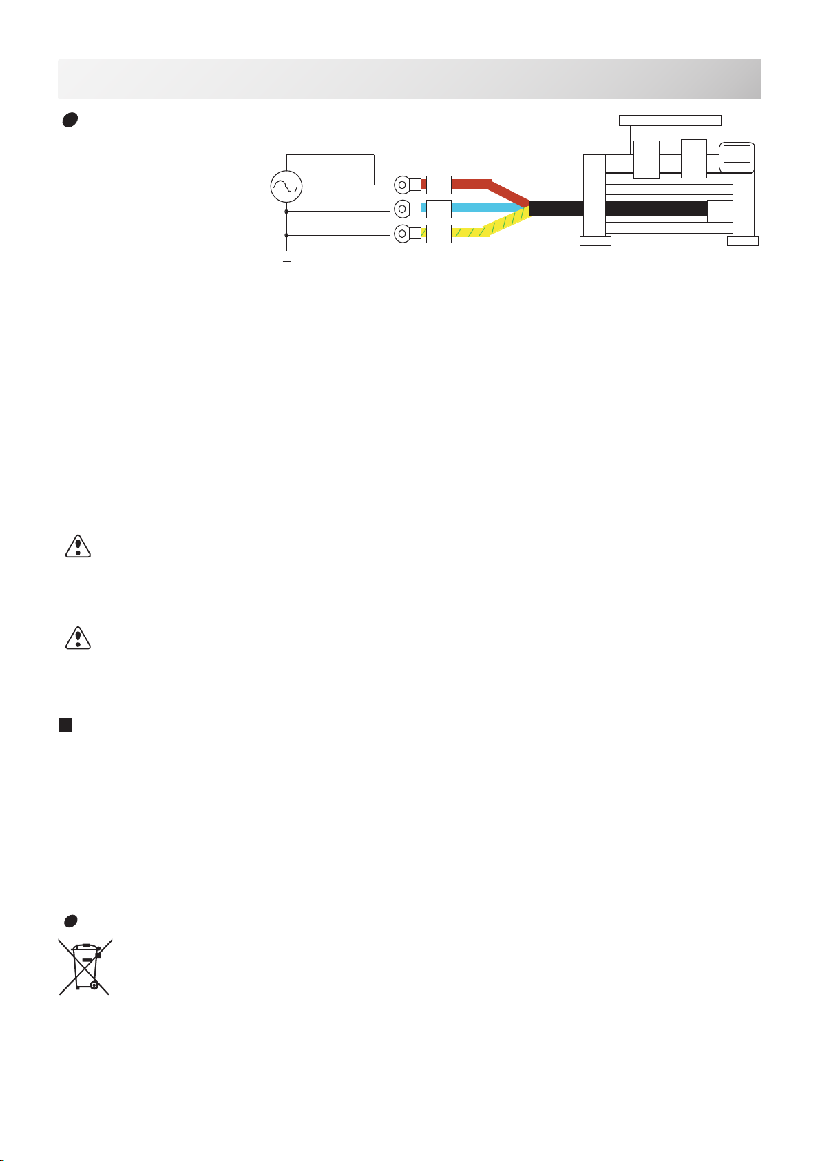
The power cable from the machine has 3 cords which are L(Live: Brown), N(Neutral: Blue) and
PE(Earth:Yellow/Green).
Connect brown cord to Live, blue cord to Neutral and yellow/green cord to Earth.
In case a plug is used for power connection, a plug has to have more capacity than voltage and
ampere of the machine (Recommendation: More than AC250V 10A), and which is following
safety standard of country.
The power cable from the machine
• Across Section (Wire) 2.5mm ^2 (AWG14) X 3
• Cord diameter (Outer) 9 - 10mm
CAUTION - Connection to power source, earth and a plug should be done by
qualified electric engineer.
If there is question, please contact with service staffof a agent.
DANGER - Connect to earth tightly.
Looseness of connection to earth causes machine trouble, electric leakage and a fire.
In case using a breaker with electric leakage detector, please use a breaker which has
detecting function for leakage of high frequency current. If breaker does not have this function,
power trip can be happened frequently.
Connection to power source
N
L
PE
Commercial
power source
Live
M4 Terminal
Brown
Blue
Yellow / Green
Earth
Neutral
Disposal of a battery
A battery is had built-in to this embroidery machine.
When you dispose of a battery, according to each country or a method
determined in each area, please dispose appropriately.
-3A -9
SETTING UP THE MACHINE
for qualied personnel only
2_2 R119
2-2
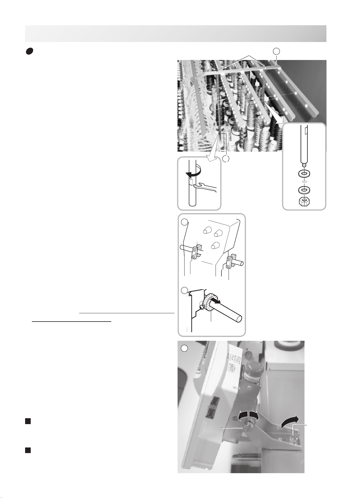
Assemble machine unit
1.Turn the Thread guide pillar clockwise with a
spanner until tight.
Fix Rear thread guide pillar with a washer
and a nut (M8).
2.InstalltheThreadguideassʼywithsupplied
screws (pan head screw M4 X 8).
3.Please off all shipping blocks.
2-head machine : 1, 2 heads
4-head machine : 1, 2, 4 heads
6-head machine : 1, 3, 6 heads
8-head machine : 1, 5, 8 heads
4.Unscrew and remove the Shipping collars (or
blocks) that are equipped on the both side of
the guide bar. (Keep the shipping collars. It is
necessarywhenpacking.)
5.Loose the Knob screw and adjust an angle
of Control box, and tight the Knob screw for
xinganangleofControlbox.
6.InstalltheArmfortubularembroidery.Please
refer to (page 6-1) “Installing and removing
the tubular frame bracket”.
Or, Install the Cap frame for the cap
embroidery.Pleasereferto(page7-1)“CAP
FRAME”.
When taking the machine apart in case
of packing, the process is opposite of
assemblingthemachine.Pleasedoexactly
theoppositewayofassembling.
When packing the machine up for
transportation, be sure to select the eighth
needleandxitwithShippingcollarsonthe
both side of the Guide bar.
2
Thread guide pillar
Threadguideassʼy
Knob
Screws
Knob
5
Shipping collars
Shipping blocks
4
2-head machine : 1, 2 heads
4-head machine : 1, 2, 4
heads
6-head machine : 1, 3, 6
heads
8-head machine : 1, 5, 8
heads
3
1
-RA -82-3 P821
2-3
SETTING UPTHE MACHINE
for qualified personnel only
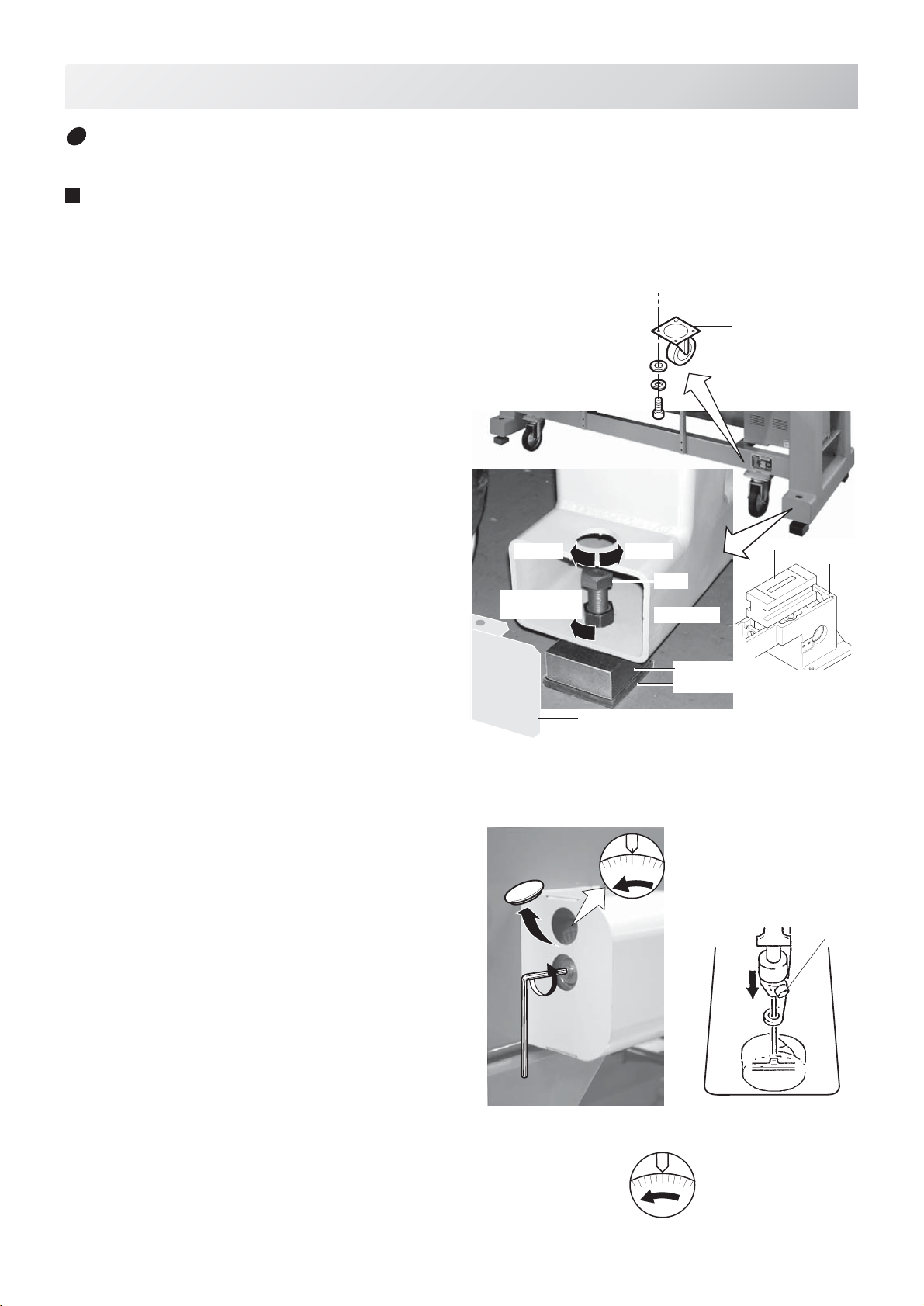
1. Please set four Casters to machine for easy
movement.
Each machine has the Caster suitable size for
the weight of the machine.
Please do not put Caster from different weight
machine.
2. Place Block base and Rubber mount under
bolts and adjust bolts so that the machine
becomes level.
Block bases and Rubber mounts are
included in accessories.
At this moment, get Caster slightly risen
from the floor.
As shown in Fig. 1, levelers should be
placed on both sides of Head bed with
Upper cover removed.
Fix Pipe covers.
Pipe covers are included in accessories.
3. Remove Needle plates and Bobbin cases
from all the heads.
4. Please set main shaft position to C point.
and pressing down the Needle holder by
your finger.
You can turn main shaft using by Six square
wrench of 5mm size turns in the direction of
the arrow.
5. Turn Main shaft by using the 5mm wrench
in direction shown with arrow mark and set
the angle of the Adjustment disk as shown
in Fig. 4.
Fig 2
L+10°
Fig. 3
Fig. 4
Fig. 1
Lock nut
Tighten
the lock nut
LowerHigher
Bolt
Pipe cover
Water level
Head bed
Block base
Rubber mount
Machine installation
Do not run the machine before setting it properly.
Make sure of taking the following steps to set the machine.
C
Adjustment
disk Needle holder
Needle
holder
Caster
-RA -9
2-4 OB27
2-4
SETTING UP THE MACHINE
for qualified personnel only
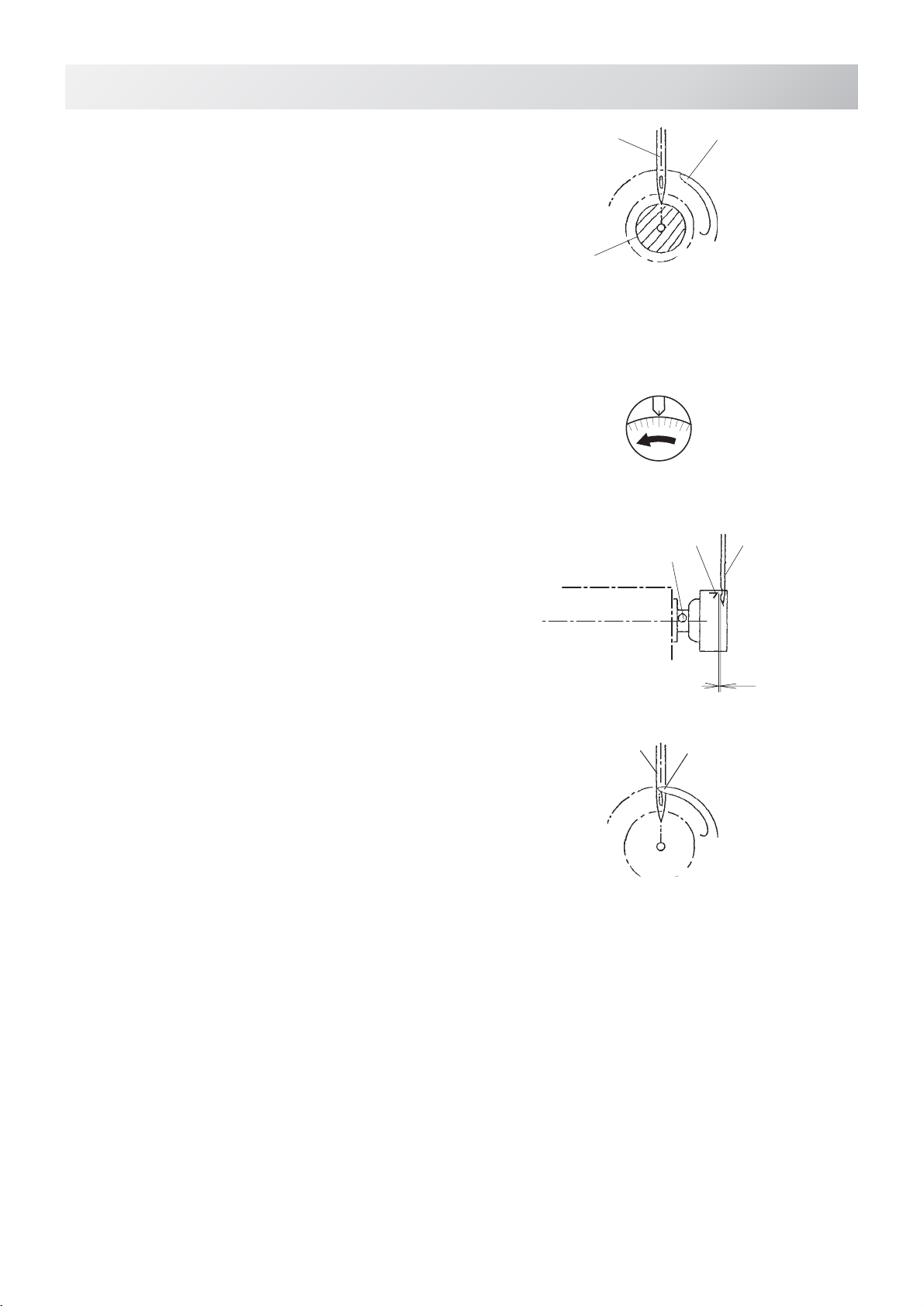
6. Check the needle depth on all Needles.
Pull white plastic φ17 measuring gauge in
and out of Rotary hook in fig. 7.
If height gauge brushes lightly against tip of
Needle, needle height is correct.
If not, loosen Needle bar block screw to
adjust, then re-tighten after adjustment.
(Remove the gauge when finished).
Note: Height gauge is contained in tool box.
7. Turn Main shaft slightly in direction shown
by the arrow mark.
Then set the angle of Adjustment disc as
shown in Fig. 6.
Note the space or timing between needle
and tip of Rotary hook as shown Fig. 7, 8.
If the space is too open or too close, loosen
3 screws of shuttle to adjust.
Make sure to tighten 3 screws after
adjusted the space.
(The timing is set exactly at the factory.
However, in some cases timing is
inadvertently thrown off from handling
during shipment.)
8. Turn Main shaft in direction and set to C
point.
Place the Bobbin and Bobbin case in the
Hook and replace the Needle plate and
tighten.
9. Machine is now ready for sewing.
Cord Rotary hook
Needle
ø17 Measuring gauge
Fig. 8
Fig. 7
Fig. 6
Fig. 5
L+25°
Tip of rotary hook
Needle
Screws
Needle
Tip of rotary hook
0.1~0.15mm
Head bed
0.1~0.2mm

-R3 -92-4b P801
2-5
SETTING UP THE MACHINE
for qualied personnel only
Middle set screw
Installation of parts for Removable table
Table clamping parts are packed separately.
Please set all Clamps when you set Remov-
able table to the machine.
1. Please set Clamp as showing picture by 4
set screws (3.5x26mm) to back side of the
Table.
2. Insert “Table prop B” to Stopper side
“Table prop A”.
Please set Stopper to hole for stopper.
(Set screw 3.5X16)
Please set Knob bolt.
( Except model HCR-1502, 1504 )
1
2
Knob bolt
Table
prop A
Table
prop B
Hole for
Stopper Stopper side “Table prop A”
Turn Table stay
The Table stay setting ipped side from
factory for safety purpose.
1. Please remove the Middle set screw and
pulling out the Table stay.
Then insert Table stay front side of Hole
for screw and insert the Middle set screw.
Hole for screw
Table stay

-3A -14
Clamp Fig. 5
Upper set screw Table stay
2-6 S604
2-6
SETTING UP THE MACHINE
Assemble
Removable table
and Border frame
1. Make sure that power source of the
machine is off.
2. Make sure that all Rotary hook
covers are shut.
If Rotary hook cover is not shut, the Table
will hit Rotary hook and damage it.
3. Remove middle set screw on Table
stay, extend Table stay as illustrated
in Fig. 1 and insert middle set screw.
4. As shown in Fig. 3, insert Removable
table in order of left, right and center
(last time).
As shown in Fig. 4, check rear edge
of the Removable table from bottom
and conrm that each table prop
plate are inserted and there is no
gap between Removable table and
Pre-xed table.As shown in Fig.
2, x set upper set screw on each
Table.
To prevent removable table from falling down, x
screws immediately.
5. As shown in Fig. 5,6, shut all clamps.
6. As shown in Fig. 5, insert Table prop
B and tighten Knob bolts.
Tighten middle set screws which are
inserted as step 3.
7. Fix the Border frame under the
bracket of the X carriage and tighten
the Knob screw lightly.
Tighten Knob screw pulling Border
frame toward an arrow mark (to your
side).
Combination of table type and number of Clamp are depending
on model type.
Please reverse procedure when remove the Table and the Border
frame.
Fig. 7
Knob bolts
Table prop
Stopper
Border frame
Knob screw
Fig. 8
Fig. 1Middle set screw
Removable table Fig. 3
Fig. 2
Upper set
screw
5
1
2
3
4
Gap between Removable table
and Pre-xed table
Fig. 4
Table prop plate
Fig. 6
Your side

-3A -152-6b S604
2-6b
SETTING UP THE MACHINE
Removing of Removable table
and Border frame
1. Make sure that power source of the
machine is off.
2. Make sure that all Rotary hook
covers are shut.
If Rotary hook cover is not shut, the Table
will hit Rotary hook and damage it.
3. Remove all knob screw indicated in
arrow mark on back of the Border
frame and take out Border frame
slowly toward you as shown in Fig.
1.
4. Loosen all of the Knob bolts on the
reverse side of the Table slightly, pull
the Table prop B till it hits Stopper as
shown in Fig. 2.
5. Open all Clumps indicated by an
arrow mark as shown in Fig. 4, 5.
6. Unscrew set screws on Table stay
in order of center, right and left, then
pull out Removable table slowly
toward you.
To prevent the table from falling down, be sure to
take off set screws immediately before pulling out
the table.
7. Remove middle set screw on Table
stay, shrink Table stay as illustrated
in Fig. 8 and insert middle set screw.
8. As shown in Fig. 6, 7, insert
removable table to Bracket in order
of right, left and center (last time)
and slide it deep inside. Fix set
screws on each Table.
To prevent removable table from falling down, x
screws immediately.
9. As shown in Fig. 6, tighten middle
set screw, shut all clamps, insert
Table prop and tighten knob bolts. Upper set screw
Middle set screw
Table support
Removable table
Fig. 6
Clamp Fig. 5
Fig. 3
Fig. 8
Middle set screw
Upper set screw Table stay
Combination of Table type and number of Clamp are depending
on model type.
Please reverse procedure when x the Table and the Border
frame.
Insert set screw lightly as shown in Fig. 1 for mounting Border
frame and tighten set screw pulling Border frame toward an arrow
mark (to your side).
Border frame
Knob screw
Fig. 1
Your side
Fig. 2
Knob bolts
Table prop
Stopper
Fig. 4
5
1
2
3
4
Table support
Fig. 7
Bracket
-R3 -122-7 PA21
2-7
SETTING UP THE MACHINE
Center support
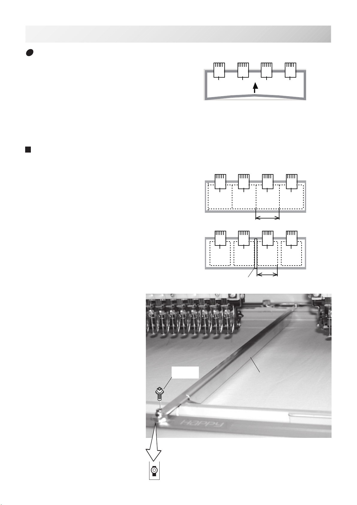
If you embroider patterns dense in stitches like
wappen to the brim of border frame, front part
of border frame is pulled inside by shrinkage of
fabric and there is a chance that front part of
border frame bends as shown in Fig.1.
If front part of border frame bends, it causes off
registration.
If you embroider under such condition, please
x center support in the center of border frame.
Please reverse procedure when remove the
table.
✽ If you x center support in border frame,
neighboring area is reduced by 35mm as
shown.
If you misplace pattern, needle and presser
foot hit border frame and cause breakage.
Please pay care in this respect.
X-35mm
X
Center support
Set screw
(M4 x 10) Center support
1. Spread fabric in border frame and
hold it with clips.
2. As shown in Fig. 3, x center
support in the center of border
frame with set screws.
At this moment, long xing hole
should face toward you.
Fig. 2
Fig. 3
Fig. 1
-CR -142-8 H901
2-8
SETTING UP THE MACHINE
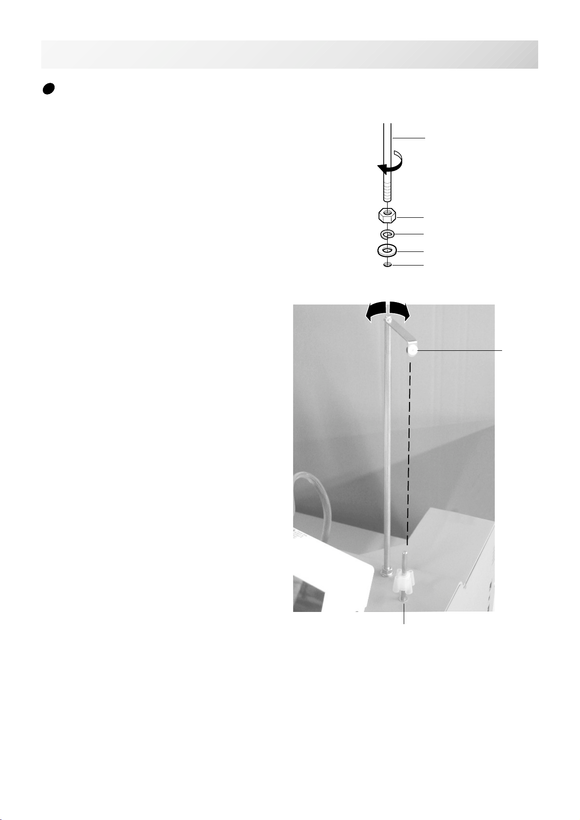
1. Attach nut, spring washer and washer to the
bobbin thread guide, then fix into the hole
on machine base, which is located behind of
control box.
2. Adjust a position of eyelet on bobbin thread
guide to a position above of thread stand
pin, and fix nut.
Bobbin thread guide
Assemble bobbin winder (Option)
Nut
Spring washer
Washer
Hole on machine base
Eyelet
Thread stand pin

-3A -18
MAIN PARTS
1. Control box
2. X carriage
3. Y carriage
4. Thread cone stand
5. Head
6. Thread tension unit
7. Adjustment disc
8. Main unit
9. Power switch
When turning off the machine, be
sure to press (Power off)
key on the control box to turn off
the machine. 5-1c
10.Head bed
11.Table stay
3_1 V601
3-1
1
23 7 541617 6 15
18
9
11 8 13
10
14 12
12.Caster
13.Adjuster
14. Removable table
15.Needle bar selection knob
16.Operation panel
17.Thread break detecting unit
18.Emergency stop button

-3A -193_2 V601
3-2
MAIN PARTS
28.糸巻き軸
29.ボビン押さえ
30.糸調子
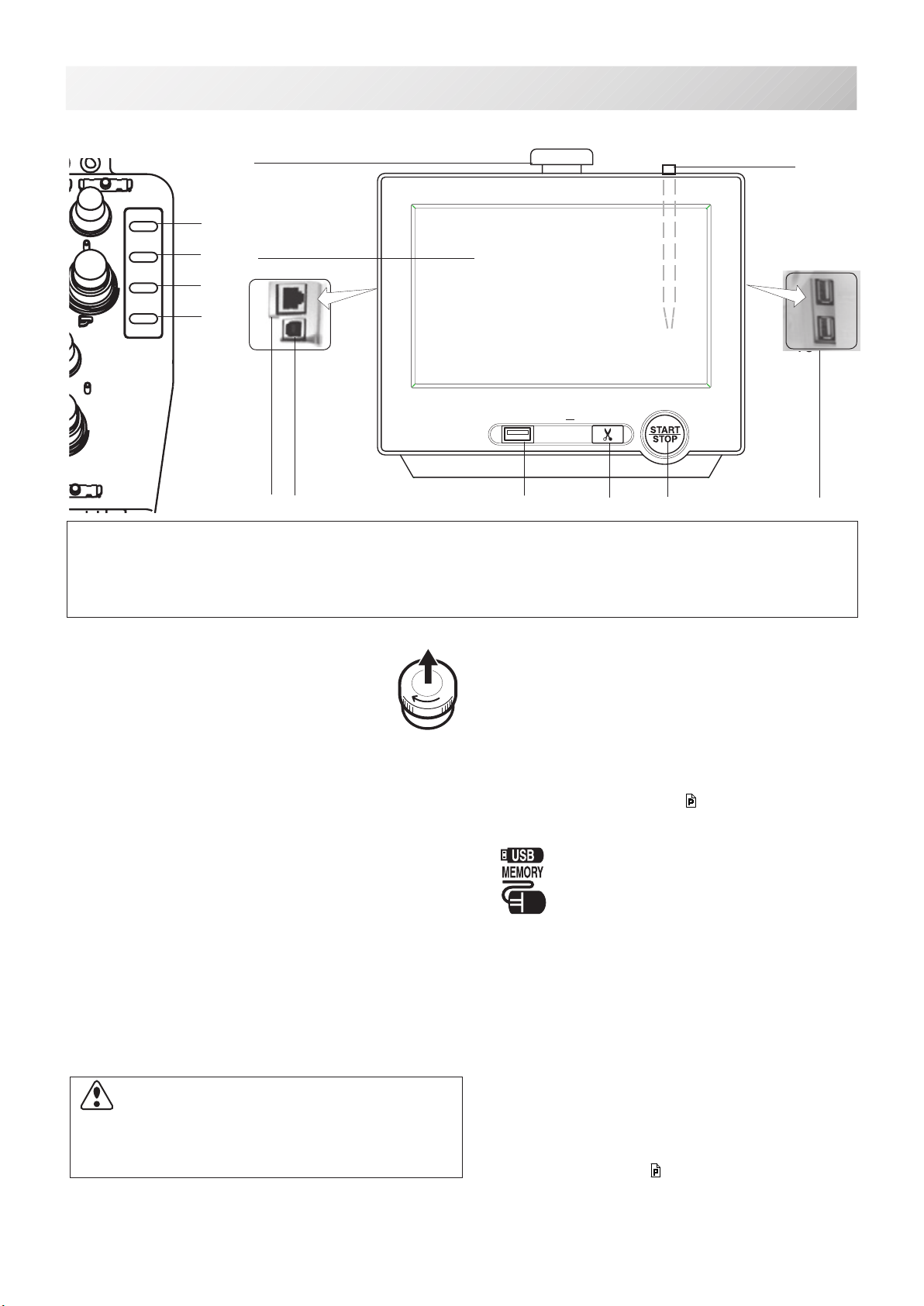
STANDARD CONTROL BOX
1. Emergency stop button
2. Display (L.C.D.)
3. LAN port
4. Thread cut button
5. Start/Stop button
6. USB port (Standard-A
receptacle)
7. USB port (Standard-B receptacle)
8. Stylus
1
2
456
16
37
8
1
2
45
8
376
10.4” CONTROL BOX (Option)
CAUTION
Do not charge your smartphone etc via the USB port
(Standard-A receptacle)
.
If you make a mistake, you can not operate the control box or can not read from the USB
port.
In this cace disconnect the USB cord and turn it back on once.
6
6
-R2 -10
3_2b N701
3-2b
MAIN PARTS
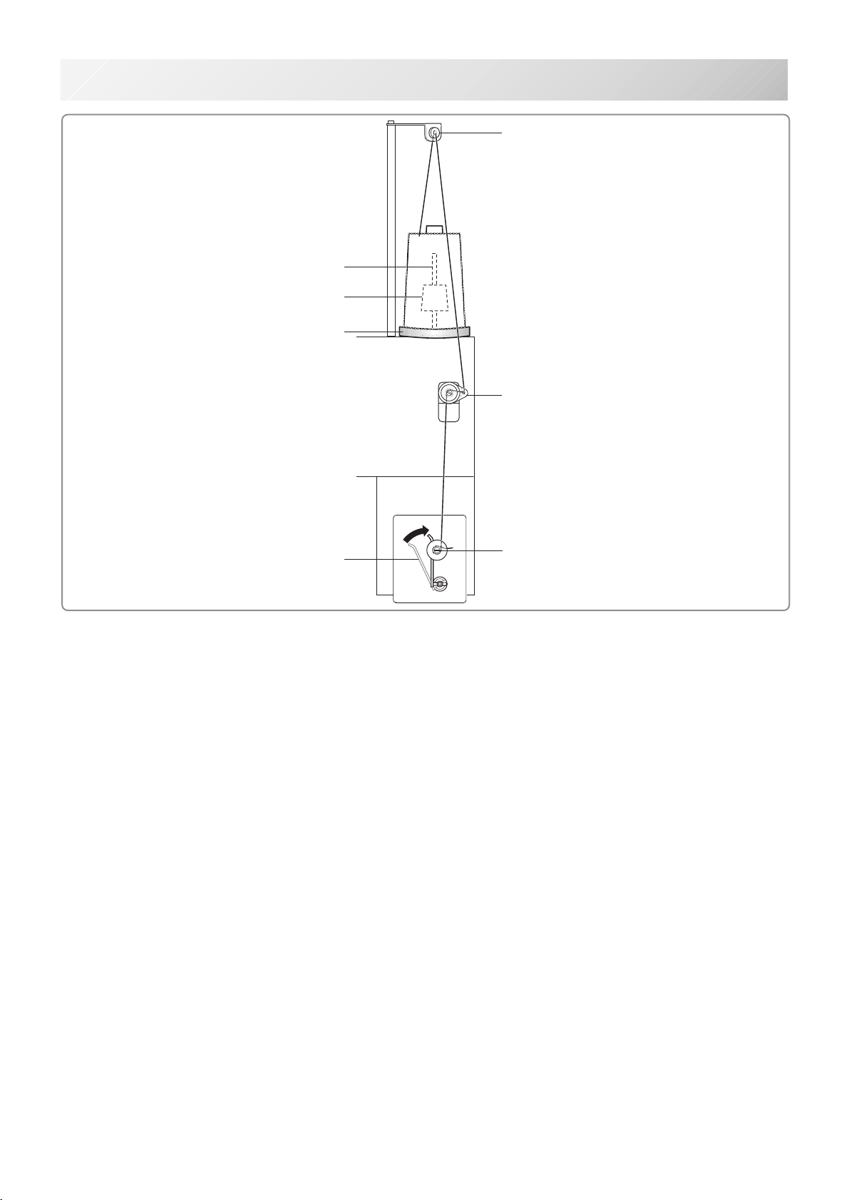
1. Thread guide
2. Thread tension
3. Spindle
4. Lever
5. Thread stand pin
6. Plastic spring
7. Thread stand felt
BOBBIN WINDING
(Option)
1
2
3
4
5
6
7
-3A -27
THE CONTROL BOX
3_8 V601
3-3
1
2
456
16
7
3
8
9
10
11
4
MENDING
THREAD
BREAK
DETECT.
ON
OFF
JUMP
FWD
START
CUT
STOP
STANDARD CONTROL BOX / 10.4” CONTROL BOX (Option)
OPERATION
2. Display (Touch screen)
Shows the embroidery design name, the number
of the current needle and other machine generated
messages.
Menu and keys in the display can be operated with
a nger or built-in stylus.
3. LAN port
You can connect PC with a LAN.
4. Thread trim button
The Machine will cut the upper and lower thread
when this button is pressed.
In case you press and keep (around 2 sec.), you
can cut only bobbin thread.
machine will stop.
Green .......... Machine ready to sew.
Main menu also accessible by
pressing MENU, which causes menu
to display.
Blinking red.. Indicates the upper thread has bro-
ken or the Bobbin thread has run out.
Red.............. Machine is running.
Orange ........ Machine has detected an error.
An error number will be shown on
the Display. 24-1
6. USB port (Standard-A receptacle)
USB ash drive socket.
USB mouse socket.
Menu and keys in the display can be operated with
a commercial USB mouse.
Press right mouse button to show a mouse pointer
in the display.
7. USB port (Standard-B receptacle)
Use this port to connect the machine with PC via
USB.
8. Stylus
Stylus can be used for pressing menu and keys in
place of ngers.
Most operation can be done by ngers. Stylus is
required for some operation such as calibration for
the touch panel LCD. 18-6
Insert a stylus into the holder (slot) of control box
when not used to prevent loss of the stylus.
9. USB port (Standard-A receptacle)
USB ash drive socket.
CAUTION: To prevent accidents.
If you Press thread trim button, the needle will
penetrate the fabric. Please keep your hands
clear for your safety.
1. Emergency stop button
When pressed , the power is switched off
and the machine stops immediately.
The emergency button locks when
pressed.
To unlock, turn the button to the right, or
pull it up.
Use this button only for emergency.
CAUTION
The touch screen can be operated by nger, but in some cases sensitivity of the screen will
be affected by condition of the nger.
In such cases, please use the ngertip or built-in stylus to hit small touch targets.
5. Start/Stop button
This button starts the machine.
When pressed, while the machine is running, the
9
Other manuals for HCR3E Series
1
Table of contents
Other HappyJapan Sewing Machine manuals


 User manual")


