HappyJapan HCR3E Series User manual
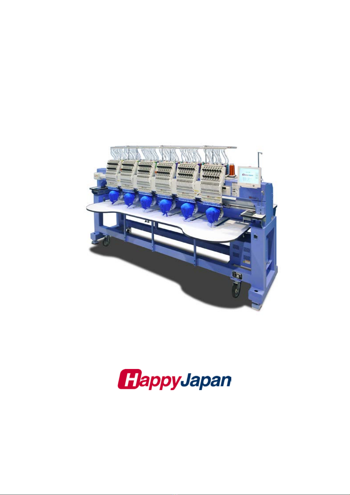
Maintenance Manual for Embroidery Machine
HCR3E SERIES
Version 1.2
HappyJapan Inc.

2
# For safe adjustment and repair #
In order to conduct adjustment and repair safely and surely,
please be sure to abide by what is mentioned in this manual to prevent trouble.
1. When you conduct adjustment and repair of this embroidery machine or handle electric related parts,
you are required to take technical lesson in advance.
2. When you conduct adjustment and repair using this manual, please be sure to use together with instruction
with it in hand.
# Please conduct in accordance with work process in this manual.
# In case there are no specific instructions or explanations in work process.
please be sure to unplug cord from receptacle.
# When you exchange parts, please be sure to use genuine parts designated by us.
# Please never remodel the embroidery machine.
When you handle circuit boards:
# In order to prevent troubles from static electricity, please remove earth from human body.
# Please don't touch metal part of circuit board with bare hand as it will short-circuit
and threaten to break circuit boards.
# When you removed circuits boards from the machine or you store or transport them,
please wrap them in static electricity preventive bag and avoid to give shock.

3
Index
Page
For safe adjustment and repair .............................................................................................................2
Index ................................................................................................................................3
Special tool, Measuring equipment, Other ............................................................................................9
1 Placement of key mechanical parts...............................................................................................11
2 Setting up the machine
2-1 Machine installation.....................................................................................................13
2-2 Assemble the thread guide..............................................................................................13
2-3 Removal of stopper ........................................................................................................14
2-4 Check of needle position.................................................................................................14
2-5 Check of needle height ...................................................................................................15
2-6 Check of rotary hook timing.............................................................................................16
2-7 Oiling ...........................................................................................................................16
2-8 Check of thread path ......................................................................................................17
2-9 Threading ....................................................................................................................20
2-10 Trial sewing ...............................................................................................................21
3 Basic maintenance
3-1 Fixing of needle...........................................................................................................22
3-2 Selection of thread ......................................................................................................23
3-3 Relation between needle and upper thread ................................................................24
4 Exchange and Setting of mechanical related component
4-1 Fixed head
4-1-1 Exchange of needle bar driver ..................................................................25
4-1-2 Adjustment of take-up lever timing............................................................27
4-1-3 Check of height of pressure foot ...............................................................29
4-1-4 Adjustment of height of pressure foot .......................................................30
4-1-5 Exchange of pressure foot........................................................................31
4-1-6 Adjustment of thread catcher....................................................................33
4-1-7 Exchange of thread catcher guide ............................................................35
4-1-8 Exchange of pressure foot cam ................................................................36
4-1-9 Adjustment of fixing of jump solenoid .......................................................38
4-1-10 Disassembling and Cleaning of jump solenoid .......................................39

4
Index
Page
4-2 Moving head
4-2-1 Assemble and remove moving head (except for 1st head) .......................40
4-2-2 Assemble and remove moving head (1st Head) ........................................44
4-2-3 Adjustment of needle position (back and forth) ...................................... 49
4-2-4 Adjustment of needle position (left and right) Adjust for 1st head ........... 50
4-2-5 Adjustment of needle position (left and right) Adjustfor2ndtolasteachhead 52
4-2-6 Adjustment of needle height .....................................................................53
4-2-7 Adjustment of needle bar lowest point......................................................55
4-2-8 Adjustment of needle bar stopper……………………………………… 57
4-2-9 Exchange of needle bar, needle bar spring, cushion and pressure foot block .................59
4-2-10 Fixing of needle bar boss check plate ....................................................61
4-2-11 Exchange of take-up lever ......................................................................62
4-2-12 Adjustment of tension of thread adjusting spring....................................64
4-2-13 Adjustment of stroke of thread adjusting spring......................................65
4-2-14 Adjustment of thread holder....................................................................66
4-2-15 Adjustment of
clip-type thread holder.......................................................67
4-2-16 Adjustment of clip drive unit ......................................................................68
4-3 Needle bar change unit
4-3-1 Check / Adjustment of needle bar change unit .........................................70
4-4 Rotary hook
4-4-1 Adjustment of rotary hook timing ..............................................................72
4-4-2 Adjustment of retainer on rotary hook.......................................................74
4-4-3 Exchange of rotary hook shaft ..................................................................75
4-5 Thread cut unit
4-5-1 Check of thread cutting driver...................................................................78
4-5-2 Adjustment of thread cutting driver ...........................................................80
4-5-3 Exchange of moving knife.........................................................................82
4-5-4 Exchange of fixed knife.............................................................................83
4-5-5 Check / Adjustment of position of moving knife ........................................84
4-5-6 Adjustment of moving knife and fixed knife ..............................................86
4-5-7 Adjustment of bobbin thread holder..........................................................87
4-5-8 Adjustment of position of keeper ..............................................................88

5
ndex
Page
4-6 Carriage unit
4-6-1 Adjustment of X carriage drive belt tension .............................................................90
4-6-2 Adjustment of X carriage timing belt tension............................................................92
4-6-3 Adjustment of Y carriage drive belt tension .............................................................94
4-6-4 Adjustment of Y carriage timing belt tension............................................................96
4-6-5 Adjustment of
center carriage timing belt tension.....................................................98
4-7 Transmission unit
4-7-1 Exchange of main shaft timing belt………………………………………………-…… 99
4-7-2 Adjustment of upper shaft timing belt tension ......................................................102
4-7-3 Adjustment of timing detecting unit .........................................................................103
5 User maintenance mode
5-1 How to enter user maintenance mode .....................................................................................105
5-2 Machine movement ..................................................................................................................106

6
Index
Page
E1 Placement of key electronic parts --------------------------------------------------------------------108
E2 Exchange and Setting of electric related component
E2-1 Exchange and Setting of CONT-R2 Board
(Main program Ver.B2.13.0~)----------------------------- ----------------------110
E2-2 Exchange Timing Circuit Board ----------------------------------------------------114
E2-3 Connection of Detection Circuit Board -------------------------------------------116
E2-4 Exchange TC7-8 Circuit Board -----------------------------------------------------117
E2-5 Exchange needle stop sensor and potentiometer -----------------------------118
E2-6 Exchange Thread trimming sensor ------------------------------------------------120
E2-7 Exchange X-Y Position Sensor -----------------------------------------------------121
E2-8 Exchange Breake Unit-----------------------------------------------------------------122
E2-9 Exchange Pulse Motor Driver--------------------------------------------------------123
E2-10 Exchange of switching power supply and adjustment of output voltage---124
E2-11 Exchange Cooling Fan ----------------------------------------------------------------126
E2-12 Exchange Inverter---------------------------------------------------------------------- 127
E2-13 Setting Inverter
E2-13-1 Parameter release the keep off setting parameter setting-------- 128
E2-13-2 Initialize parameter---------------------------------------------------------- 130
E3 Parts Replacement in control box and setting
E3-1 Open and remove control box ------------------------------------------------------- 131
E3-2 Remove LCD-CE board --------------------------------------------------------------- 132
E3-2a 10.4” Remove LCD-CE board ------------------------------------------------------- 134
E3-3 Setting for LCD-CE board -------------------------------------------------------------136

7
Index
Page
E4 Program update procedure---------------------------------------------------------------------------- 137
E4-1 Preparation for program update ------------------------------------------------------- 138
E4-2 Update the program------ ---------------------------------------------------------------- 139
E4-2-1 Update the main program and the machine program------------------ 139
E4-2-2 Update main program---------------------------------------------------------- 140
E4-2-3 Update machine program----------------------------------------------------- 142
E4-3 Setting of revolution----------------------------------------------------------------------- 144
Re-Initialization of machine system
Initializing of machine speed
E5 Maintenance mode
E5-1 How to enter Maintenance mode ------------------------------------------------------- 145
E5-2 Machine Test - Machine movement ---------------------------------------------------- 146
E5-3 Memory All Clear Initialization of design memory -------------------------------- 148
E5-4 Record- Operation data display --------------------------------------------------------- 149
E5-4-1 Total number of stitch ------------------------------------------------------- 149
E5-4-2 Record of Error occurrence ----------------------------------------------- 150
E5-4-3 Number of occurrence in each error display -------------------------- 151
E5-4-4 Thread break history -------------------------------------------------------- 152
E5-5 Machine setting ----------------------------------------------------------------------------- 153
E5-6 Frame Position Entry - Registration of coordinates for positioning sensor ---- 155
E5-7 Maintenance Register―Registration of machine maintenance date ---------- 158
E6 Installment and setting of option unit
E6-1 Installation of laser position marker ----------------------------------------------------- 159
E6-2 Installation of Safety sensor (front)------------------------------------------------------ 161
E6-3 Installation of Safety sensor (rear)------------------------------------------------------- 164
E6-4 Installation of bobbin thread winder ----------------------------------------------------- 167
E6-5 Installation of Upper Thread Holder ----------------------------------------------------- 169
E6-6 Adjustment of Cap drive frame ------------------------------------------------------------ 171

8
Index
Page
E7 Electric system diagram
E7-1 Pulse motor driver (PMD) wiring----------------------------------------------------------172
E7-2 Pulse motor driver (PMD) setup-----------------------------------------------------------173
E7-3 Inverter wiring--------------------------------------------------------------------------------- 174
E7-4 Electrical connection diagram------------------------------------------------------------ 175
E7-5 List of electrical connection diagram---------------------------------------------------- 178
E7-6 Explanation of function clrcuit board---------------------------------------------------- 180
E8 How to respond for some question (As example step) -------------------------------------------- 187
E9 Trouble shooting
E9-1 Electricity doesn’t turn on ------------------------------------------------------------------ 188
E9-2 Thread break ---------------------------------------------------------------------------------- 189
E9-3 Erroneous thread cut ------------------------------------------------------------------------ 194
E9-4 Off-registration of pattern ------------------------------------------------------------------- 196
E9-5 Upper thread comes off from needle hole ---------------------------------------------- 199
E9-6 Upper thread remains ----------------------------------------------------------------------- 201
E9-7 Looping------------------------------------------------------------------------------------------ 202
E9-8 Malfunction of thread break detection --------------------------------------------------- 203
E9-9 Suspension of upper shaft ----------------------------------------------------------------- 204
E9-10 Malfunction of needle bar change ------------------------------------------------------ 205
E9-11 Defect on thread catcher ------------------------------------------------------------------ 206
E9-12 Others (Mechanical)------------------------------------------------------------------------ 207
E9-13 Others (Electronically)---------------------------------------------------------------------- 208
E10 Error coping ------------------------------------------------------------------------------------------------- 209
E11 Tables for timing / adjustment value ------------------------------------------------------------------ 215
9
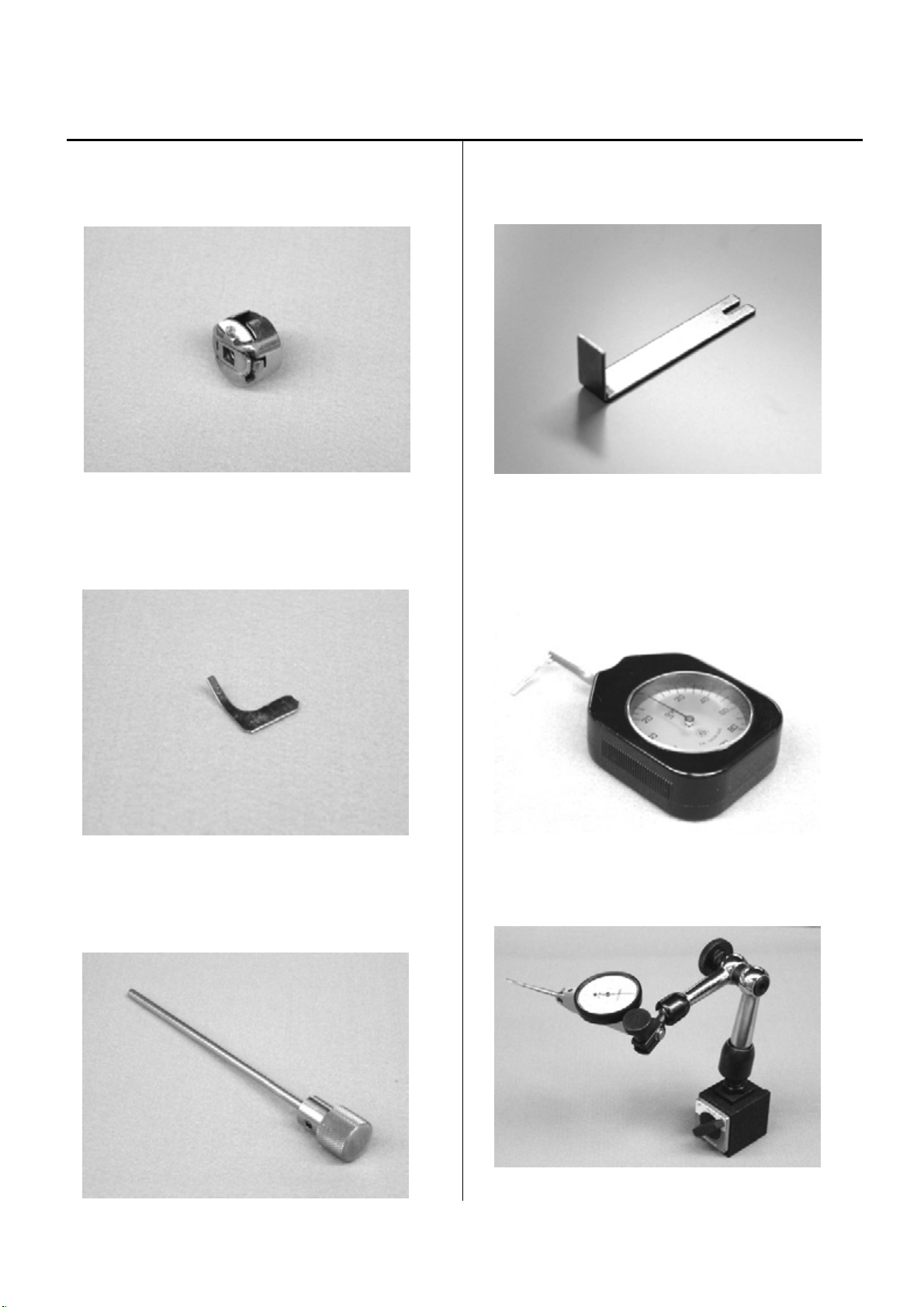
Special tool, Measuring equipment, Other
HSA90030
Keeper positioning gauge (Page 88)
HSA90080
Retainer positioning gauge [0.8mm] (Page 74)
HSA90090
Positioning pin [φ4] (Page 27)
HSA90131
1.2mm thickness gauge (Page 29, 30)
HSA90230
Tensile gauge (Page 87)
HSA90240
Dial-gauge set (Page 55)
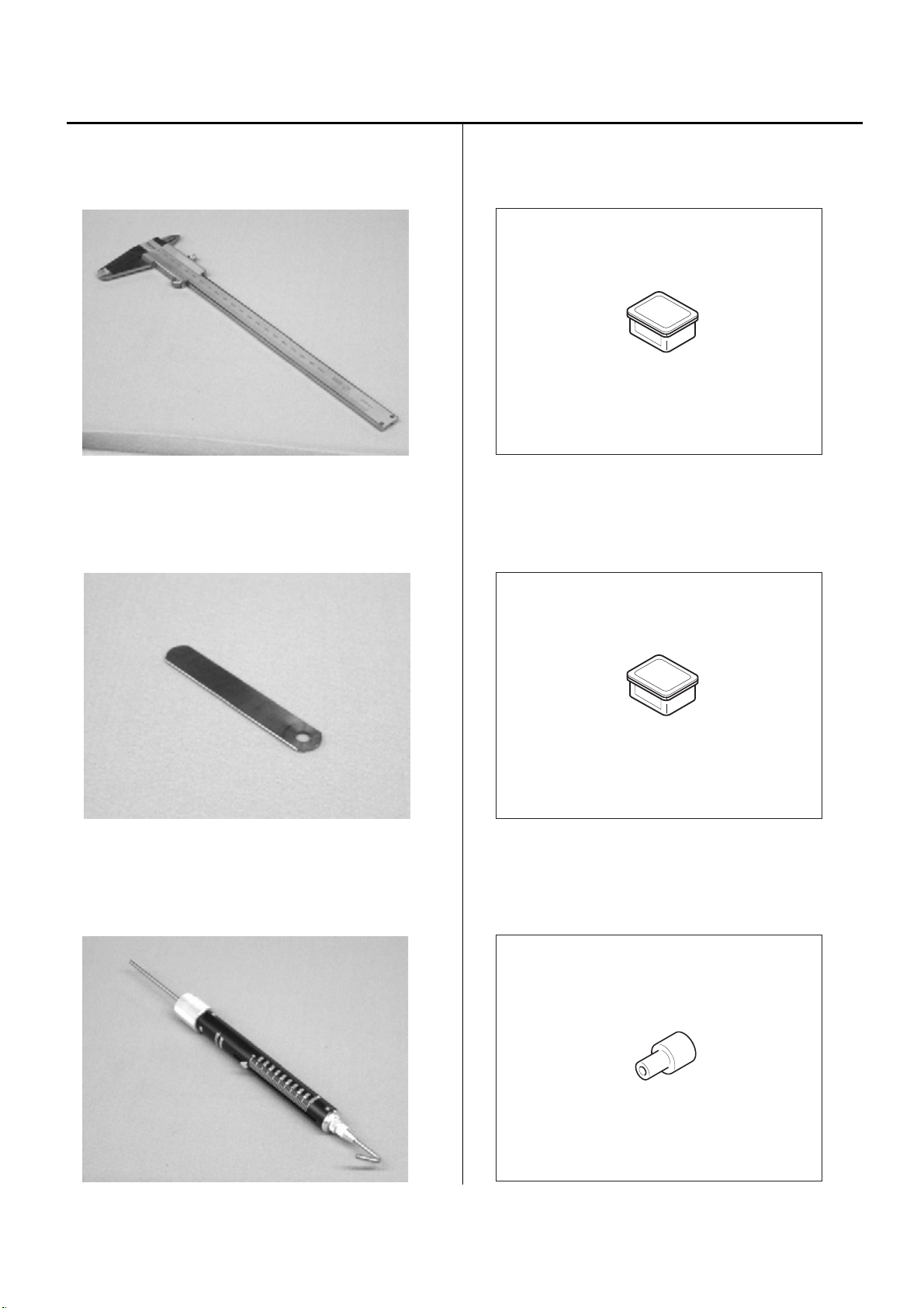
Special tool, Measuring equipment, Other
HSA90270
Vernier calliper gauge [200mm] (Page 37)
HSA90210
0.2mm thickness gauge (Page 63)
HSA90290
Tension gauge 2000Cn(1000g) (Page 92, 94, 97)
HSA90311
Shell alvania EP Grease 100g (Page 76)
HSA90340
Shell Grease7 MIL-G-23827B 50g (Page 39)
M0404342
Needle height gauge (Page 15, 53)
11
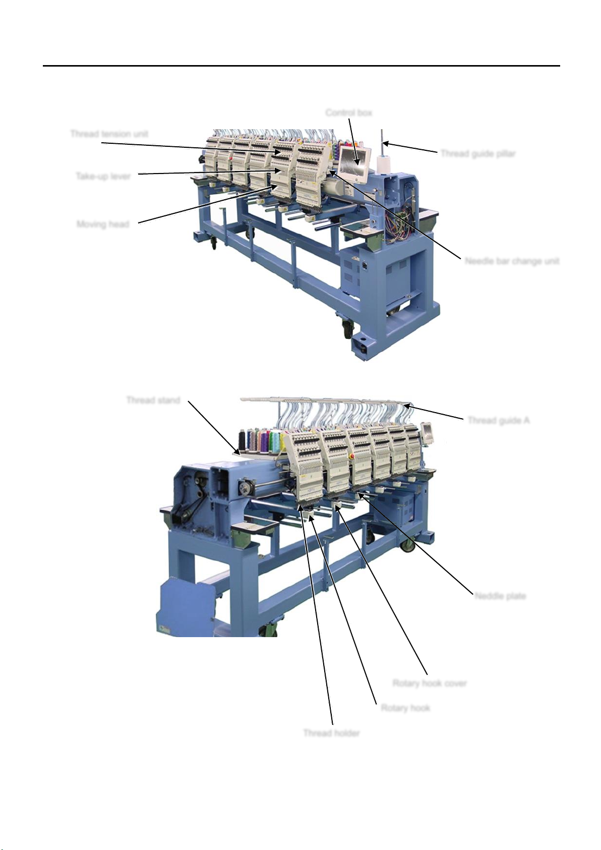
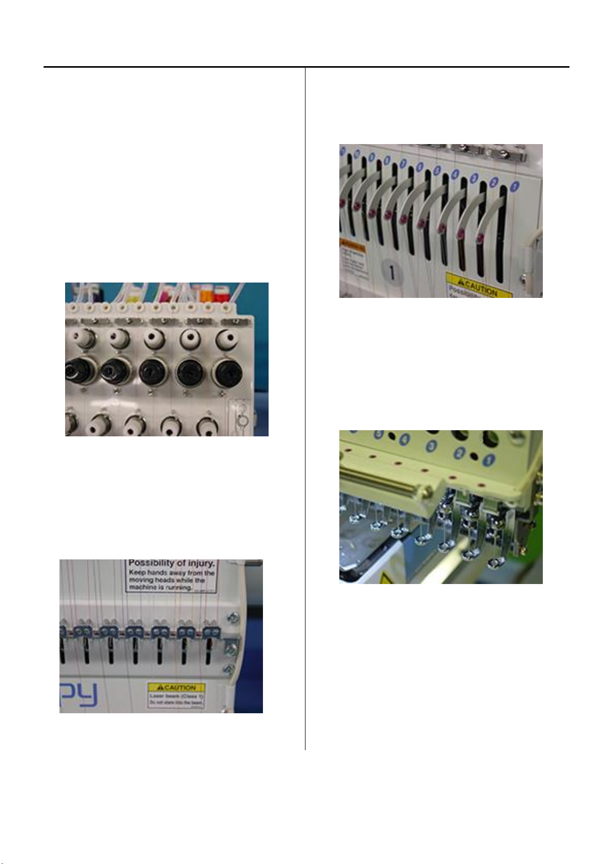
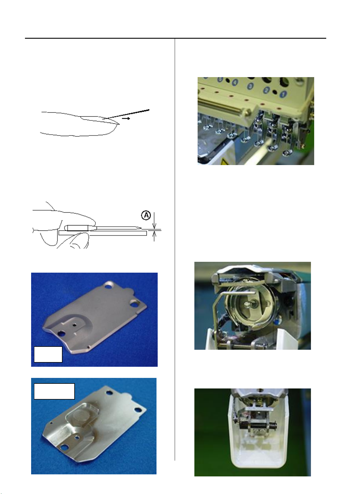
1 Placement of key mechanical parts
Thread tension unit
Take-up lever
Moving head
Control box
Thread guide pillar
Needle bar change unit
Thread guide A
Thread stand
Thread holder
Rotary hook
Rotary hook cover
Neddle plate
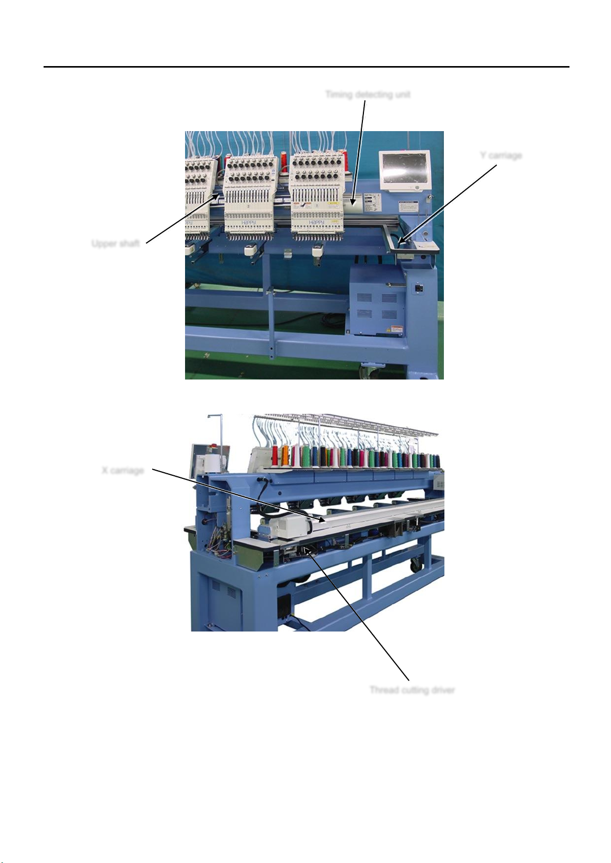
12
1 Placement of key mechanical parts
Upper shaft
Timing detecting unit
Y carriage
X carriage
Thread cutting driver
13
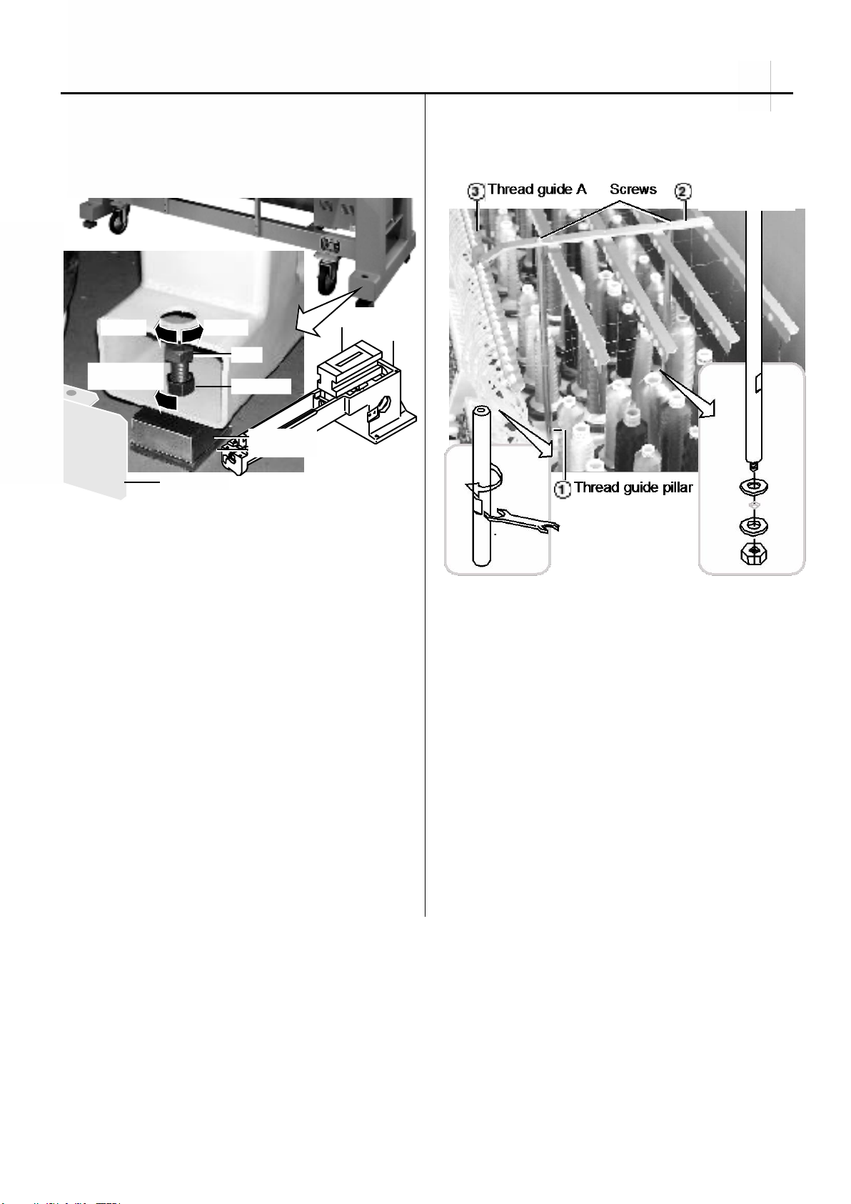
Lock nut
Tighten
the lock nut
LowerHigher
Bolt
Pipe cover
Water level
Head bed
Block base
Rubber mount
2-1, 2-2 Setting up the machine
2-1 Machine installation
(1) place block base and rubber mount under bolts and adjust
bolts so that the machine becomes level.
Block bases and rubber mounts are included in
accessories.
At this moment, get caster slightly risen from the floor.
As shown in Fig., levelers should be placed on both sides
of head bed with upper cover removed.
(2) Fix the lock nut.
(3) Fix the pipe cover.
2-2 Assemble the thread guide
(1) Turn the thread guide pillar (front [long], rear [short])
clockwise with a spanner until tight.
Fix rear thread guide pillar with a washer and a nut (M8).
<Spanner> 10mm, 13mm
(2) Install the thread guide ass'y with supplied screws (M4x8).
(3) Fix thread guide A (with spiral tube) on thread guide ass'y
with screws (M3x8) from lower side.

14
2-3, 2-4 Setting up the machine
2-3 Removal of stopper
(1) Loosen the screw and remove the red shipping collars that
are equipped on the both side of the guide bar.
(2) Remove head stopper.
< Note > Number of head stopper is depending on model.
Head stopper
2-4 Check of needle position
(1). Turn power switch ON, and enter user maintenance
mode.
Refer to [ 5 User maintenance mode ]
(2) Remove bobbin case.
(3) With help of user maintenance mode, please move needle
bar down and confirm needle position is center of needle
hole on needle plate.
< Note > Please move needle bar slowly
< Note > Please check position of 8th needle, then check
1st and 15th needle.
Needle Needle hole of needle plate
15
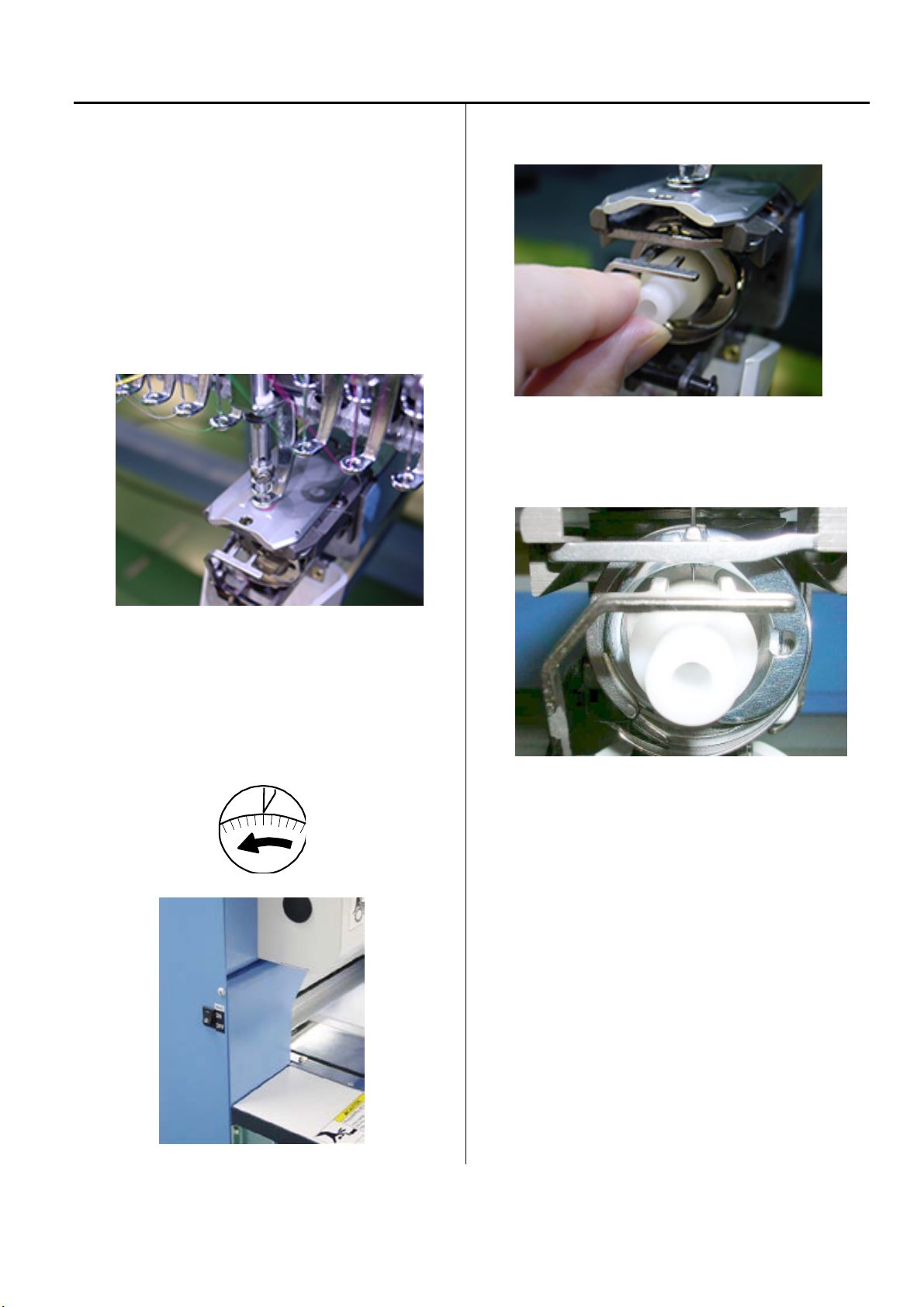
2-5 Setting up the machine
2-5 Check of needle height.
(1) Move moving head to the position which 8th needle is
active.
Remove bobbin case.
(2) Bring needle bar down.
Refer to [ 5 User maintenance mode ]
(3) Turn upper shaft anti-clockwise and set dial disc to
[ L + 10 degrees ].
Turn brake switch ON.
(4) Put needle height gauge in rotary hook.
(5) Check if the needle tip touches to the gauge slightly.
(6) Take “Needle height gauge” out from hook.
16
1
3
2
2
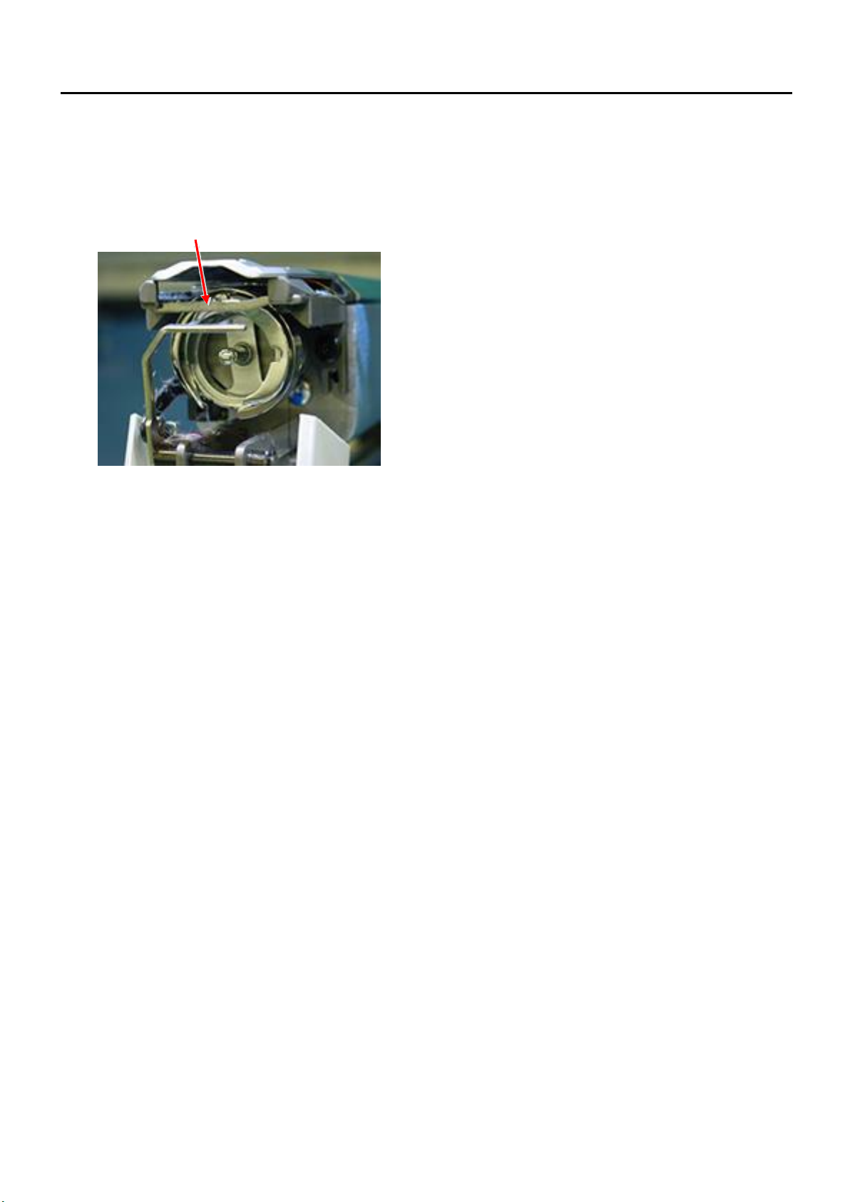
2-6, 2-7 Setting up the machine
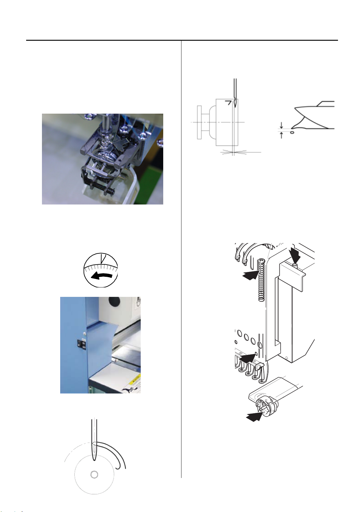
2-6 Check of rotary hook timing
(1) Remove needle plate, Move moving head to the position
which 8th needle.
Turn upper shaft and set to lowest needle position [L]
Refer to [ 5 User maintenance mode ]
(2) Turn upper shaft anti-clockwise and set dial disc to [ 25
degrees ].
Turn brake switch ON.
(3) Check the position of needle and tip of hook as below.
(4) Check the clearance between needle and rotary hook
should be [ 0.1 ~ 0.2mm ].
(5) Fix the needle plate.
2-7. Oiling
Lubricate the specified oil locations.
Oil : #10 Sewing machine oil
1) Rotary hook Between the outer and inner rotary hook
2) Needle bar
3) Head shaft
17
2-8 Setting up the machine
2-8 Check of thread path
To keep stable and high quality stitches, please keep
places where thread contacts in the best condition.
<Note> Pleas confirm that there is no burr and crack at the
position which thread is passing.
(1) Thread tension, Thread guide, Rectifier
a) Revolution must be smooth
b) No sticking of lint or dust
(2) Thread Adjusting Spring
a) No burr and crack
b) Spring move smoothly
(3) Ceramic and rim of take-up lever
a) No burr and crack
(4) Thread path in lower side and needle holder
a) No burr and crack
下面
18
2-8 Setting up the machine
(5) Needle
a) Needle tip shouldn't be warped or bent.
When you slide needle tip on surface of nail and
if the nail gets scratched.
needle tip is warped. Please exchange it with new one.
Please place needle on flat surface and check
clearance (A) from side.
If clearance is not equal, needle is bent.
Please replace it with new one.
(6) Needle plate
a) No burr and crack in needle hole and around it.
(7) Pressure foot
a) No burr and crack inside hole
b) Not bent
(8) Rotary hook
a) No burr and crack.
b) Hook point not warped.
c) Backlash between bobbin case holder and outer hook
should be less.
(9) Keeper
a) No burr and crack in needle hole and around it.
Surface
Two setscrews
19
2-8 Setting up the machine
(10) Rotary hook retainer
a) There is No burr and crack at the position which thread
pass through.
Rotary hook retainer
20
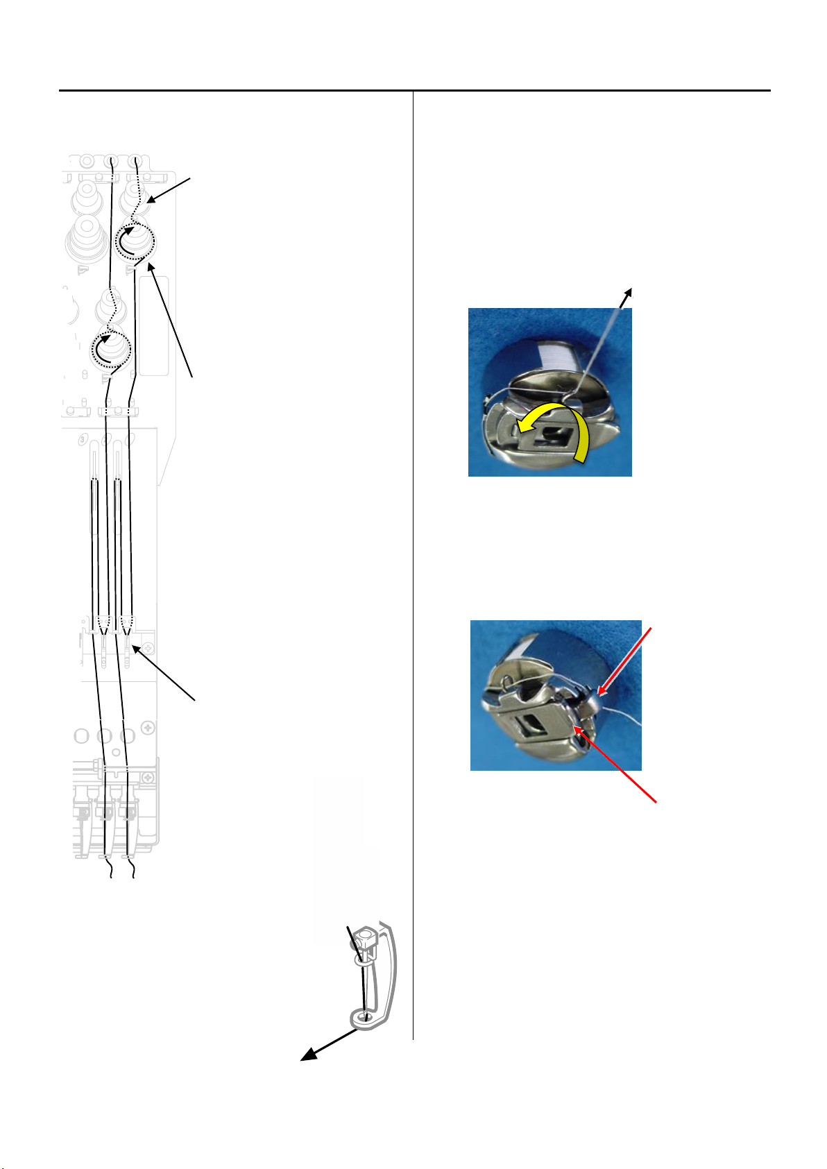
2-9 Setting up the machine
2-9 Threading
- Upper thread
Please adjust minor thread tension
unit that detection rotary is not
slipping and turn smoothly.
< Note > If tension of minor thread
tension unit is too low, detecting
rotary does not turn smoothly and
thread slip on rotary.
Detecting rotary
Please check thread is not disturbed
by spring.
Upper thread tension should be adjusted
depending on type of thread, needle and fabric
etc.
< Standard > 100 ~ 150Cn (gf)
- Bobbin thread
Bobbin thread tension is depending on adjustment of upper
thead.
Please note that bobbin will turn to arrow-marked direction
when you pull bobbin thread.
<Standard> 25 ~ 35cN(gf)
< Note > Please check thread is not disturbed by finger or
latch.
Finger
Latch
Other manuals for HCR3E Series
1
This manual suits for next models
8
Table of contents
Other HappyJapan Sewing Machine manuals
 User manual")


