HappyJapan HCS2 User manual

SAUC01-27
HCS2
Compact Single-head Embroidery Machine
Original instructions
INSTRUCTION BOOK
Program Ver. *2.23~


-SA -3
INDEX
IMPORTANT SAFETY INSTRUCTIONS... 1-1
WARNING LABELS & THEIR LOCATIONS
..... 1-2
SETTING UP THE MACHINE
Remove the machine from box............... 2-1
Accessories............................................. 2-3
Assemble machine unit........................... 2-4
Machine installation ................................ 2-5
Grounding instruction.............................. 2-7
Disposal of a battery ............................... 2-7
MAIN PARTS............................................. 3-1
THE CONTROL BOX ................................ 3-3
DRIVE MODE............................................ 3-4
Frame change................................... 3-8a
MENU................................................... 3-A
INSERTING A NEEDLE............................. 4-1
SELECT NEEDLES AND THREADS ....... 4-2
BACKING MATERIALS ............................. 4-3
BOBBIN WINDING
Winding the bobbin ................................. 4-4
Removing the bobbin.............................. 4-5
Inserting the bobbin ................................ 4-5
Adjusting bobbin thread tension.............. 4-5
Inserting the bobbin case........................ 4-5
THREADING THE MACHINE
How to thread upper thread .................... 4-6
HOW TO READ THESE INSTRUCTIONS and SCROLLBAR
4-8
DISPLAYING THE PATTERN IN SETTING MODE
... 4-9
TURNING THE MACHINE ON
How to turn on the machine.................... 5-1
How to turn off the machine.................... 5-1c
Calendar and clock setting...................... 5-2
MESSAGE................................................. 5-3
PREPARATION OF PATTERN DATA
Connecting to a PC................................. 5-4
Reading embroidery pattern data from
the PC
.....................................................5-4b
Read embroidery pattern data ............... 5-5
Reading pattern data .............................. 5-6
Selection of folders ................................. 5-9
How to select patterns from memory ...... 5-A
Erasing patterns from memory................ 5-B
NEEDLE BAR SELECTION ......................5-E
SEWING WITH TUBULAR FRAMES
Installing and removing the frame base.. 6-1
How to hoop............................................ 6-2
Putting the hoop on the machine ............ 6-3
Starting to embroider .............................. 6-4
CAP FRAME (OPTION)
Changing the needle plate...................... 7-1
Installing and removing the cap drive frame
.. 7-2
Normal cap frame ................................... 7-5
Wide cap frame....................................... 7-8
Starting to embroider ..............................7-B
ADJUSTING THE THREAD TENSIONS... 8-1
ADJUSTING THE LASER POINTER (OPTION)
.. 8-2
SEWING
What to do if the thread breaks while sewing
9-1
Stopping and resuming sewing............... 9-1
Loss of power while embroidering .......... 9-2
Moving the hoop while embroidering and then returning to
the correct location (Position)
............................. 9-3
Moving back to the starting point (Origin) 9-3
Going back to the beginning of the design (Top)
... 9-4
Placing the design in the center of the selected
embroidery frame
(Center)
........................... 9-4
Rotating and mirroring designs (Convert)
.. 9-5
Starting in the middle of a design (Position) ...
9-6
POSITION ALIGNMENT BY DEFINING 2 POINTS
.. 9-8
POSITION .................................................9-B
Piece number.......................................... 9-C
Bobbin thread alarm..............................9-Ca
Work save .............................................9-Ce
REGISTER ................................................9-D
Entry........................................................ 9-E
Return .....................................................9-F
READING
Join ....................................................... 10-1
Pattern Read Settings........................... 10-3
PATTERN
Locking pattern data ..............................11-1
Trace type ..............................................11-2
Export.....................................................11-3
Renaming patterns.................................11-5
Copying pattern data..............................11-6
Moving pattern data ...............................11-7
Renaming folders...................................11-9
Sort ........................................................11-A
Thread break report .............................. 11-B
0_1 UC01
0-1

-SA -4
INDEX
0_2 UC01
0-2
Retrieve built-in data from machine ...... 11-C
Searching pattern data.......................... 11-D
NEEDLE BAR SELECTION .................... 12-1
Auto setting................................................12-2
Thread color...............................................12-4
Color change data registration...................12-6
Color change data read .............................12-7
Repetition of color group setting................12-8
FRAME CONFIRMATION ............................13-1
Frame selection
............................................13-2
Adjusted for embroidery area ....................13-4
User-dened frames (1 ~ 5).......................13-7
User-dened frames (6 ~ 20).................... 13-A
How to change center point of frame (1 ~ 5, 6 ~ 20)
..... 13-H
Non registered .......................................... 13-J
PATTERN SETTINGS ..................................14-1
Scaling .......................................................14-2
Width adjustment .......................................14-3
Angle..........................................................14-4
Repeat sewing ...........................................14-5
Auto origin..................................................14-7
Offset .........................................................14-8
Frame out ................................................. 14-D
MACHINE SETTINGS..................................15-1
LOCK STITCHES.........................................15-5
LETTER........................................................16-1
QUEUE.........................................................17-1
Alter and Execution ...................................17-2
Needle bar selection and Pattern settings
........17-4
Registration of QUEUE setting ..................17-6
Read QUEUE setting.................................17-7
OTHER SETTINGS
Create network ..........................................18-1
Version information ....................................18-3
Language...................................................18-5
Calibrate ....................................................18-6
User maintenance mode............................18-8
Report...........................................................19-1
GUIDE ..........................................................20-1
SCREEN SAVER..........................................21-1
i-CUSTOM............................................... 22-1
LAN connection .........................................22-2b
TASK RESERVATION ............................. 22-2c
Reading................................................. 22-2d
Needle bar selection ............................. 22-2e
Setting................................................... 22-2f
Search................................................... 22-2g
List ........................................................ 22-2h
Letter..................................................... 22-2i
Layout ................................................... 22-2j
USER MANAGEMENT
Registration of administrator......................22-3
Registration of user....................................22-6
Selection of user (Login)............................22-8
Selection of user (Login) at power ON.......22-9
LAYOUT ...................................................... 22-A
THREAD SET...........................................22-J
SPECIFICATIONS • MAINTENANCE
Specications.............................................23-1
Oiling..........................................................23-1
Cleaning of rotary hook
Cleaning of thread cutting knife .................23-2
ERRORS AND WHAT TO DO ......................24-1
INITIALIZING OF MACHINE SETTINGS
Re-Initialization of machine system,
Initialize the PMS .................................. 25-1
Initializing of machine speed......................25-2
HELPFUL HINTS..........................................26-1
EMBROIDERY TERMS................................26-2
BUILT-IN FONT LIST....................................26-3
BUILT-IN PATTERNS LIST...........................26-4
VARIOUS SPECIAL FRAMES (OPTIONS)
.... 27-1

-SJ -5
IMPORTANT SAFETY INSTRUCTIONS
1_1 N401
1-1
This electrical appliance is intended for household use.
When using an electrical appliance, basic safety precautions should always be followed, includ-
ing the following.
Read all instructions before using this appliance.
DANGER - To reduce the risk of electric shock:
1. An appliance should never be left unattended when plugged in. Always unplug this appliance
from the electric outlet immediately after using and before cleaning.
WARNING
-
To reduce the risk of burns, fire, electric shock, or injury to persons:
1. Do not allow to be used as a toy. Close attention is necessary when this appliance is used
by or near children.
2. Use this appliance only for its intended use as described in this manual. Use only attach-
ments recommended by the manufacturer as contained in this manual.
3. Never operate this appliance if it has a damaged cord or plug, if it is not working properly, if it
has been dropped or damaged, or dropped into water. Return the appliance to the nearest
authorized dealer or service center for examination, repair, electrical or mechanical adjust-
ment.
4. Never operate the appliance with any air openings blocked. Keep ventilation openings of the
sewing machine and foot controller free from the accumulation of lint, dust, and loose cloth.
5. Never drop or insert any object into any opening.
6. Do not use outdoors.
7. Do not operate where aerosol (spray) products are being used or where oxygen is being
administered.
8. To disconnect, turn all controls to the off (“0”) position, then remove plug from outlet.
9. Do not unplug by pulling on cord. To unplug, grasp the plug, not the cord.
10.Keep fingers away from all moving parts. Special care is required around the sewing ma-
chine needle.
11.Always use the proper needle plate. The wrong plate can cause the needle to break.
12.Do not use bent needles.
13.Do not pull or push fabric while stitching. It may deflect the needle causing it to break.
14.Switch the sewing machine off (“0”) when making any adjustments in the needle area, such
as threading needle, changing needle, threading bobbin, or changing presser foot, etc.
15.Always unplug sewing machine from the electrical outlet when removing covers, lubricating,
or when making any other user servicing adjustments mentioned in the instruction manual.
SAVE THESE INSTRUCTIONS

-SA -5
WARNING LABELS & THEIR LOCATIONS
1_2 M201
1-2
Trapping hazard
Shut the cover when starting the machine.
Do not put hands in while the machine is running.
Trapping, Puncture, Cut hazard wherever this
label is found
Shock hazard on all electrical components
Injury risk on moving head(s)
Keep hands away from the moving heads while the
machine is running.
Laser beam (Class 1)
Do not stare into the beam.
ES-HMF-5113-0
WARNING
Shut the cover when starting the
machine. Do not put hands in
while the machine is running.
Fear of serious injury.
ES-HMF-5117-0
CAUTION
Keep hands away from the
moving heads while the
machine is running.
Possibility of injury.
CAUTION: Injury risk on frame and carriage
Keep hands away from the drive
frame while the machine is
running.
Catch a finger in the X-carriage.
WARNING: Injury risk warning
for all needles
Keep fingers away from
the needles while
the machine is running.
Laser beam (Class 1)
CAUTION
Do not stare into the beam.

-SJ -9
SETTING UP THE MACHINE
2_1 UB12
2-1
CAUTION: To prevent accidents.
The machine is quite heavy for one person to carry.
Please use two persons when unpacking or carrying.
CAUTION: To avoid problems.
Make sure to hold bottom of the machine body when
removing from the box.
Do not hold any other place. (bed, moving head, con-
trol box etc.).
We recommend unpacking should be done where it has enough room.
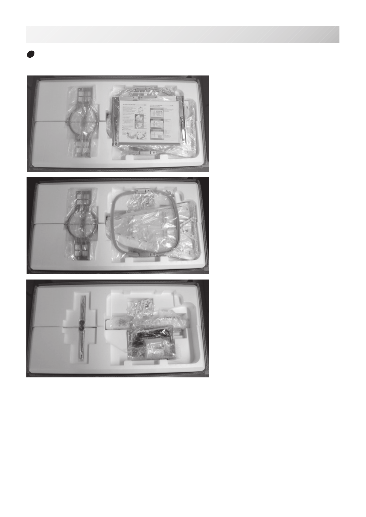
Remove the machine from box
1. Remove 2 straps from the carton.
2. Lift the box (upper) to remove.
3. Take out the accessories.
Refer to the next page.
4. Take out the styrene foam (right) and (left).
5. Take out the styrene foam (lower front), (lower
right), and (lower left).
Be careful not fall down the machine, tilt the ma-
chine slightly when taking out the styrene form
(lower right) and (lower left).
6. Carry the machine to installation location.
Please keep those packing materials in case
of necessary for repair or other reasons.
Packing procedure is the reverse from un-
packing procedure.
Straps
Box (upper)
Styrene foam
Styrene foam
Styrene foam
Styrene
Styrene
How to carry machine
The unpacked machine should be carried by 2 person with the hand position at
shown in
photos.
Right side
Left side
The person hold-
ing the machine
from right side
need to hold the
machine arm by
left hand.
Right hand
Left hand
Left hand
Right side
-SA -9
SETTING UP THE MACHINE
2_1b UC01
2-2
Placement of Accessories
Conrm all the accessories are contained when unpacking.
Frame base
USB ash drive (Instruction manual,
Parts list, Happy Link Software)
Instruction manual
Embroidery frame (Round)
Embroidery frame (Square)
Thread stand
Thread guide bracket
Carriage
Thread stand felt (13 pcs)
Power line cord ass’y
Oiler
Sewing machine oil
Thread guide pillar (2 pcs)
Thread stand pin (13 pcs)
Wave washer (13 pcs)
Front cover
Tool box
Antenn (Option WLAN)
-SA -10
18
19
SETTING UP THE MACHINE
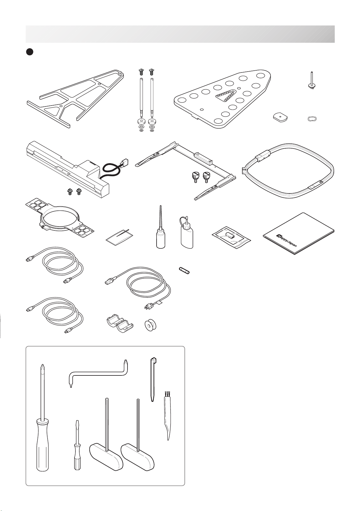
Accessories
Please conrm you have received the following.
2_2 TA02
2-3
1. Thread guide bracket
2. Thread guide pillar (2 pcs)
3. Thread stand
4. Thread stand felt (13 pcs)
5. Thread stand pin (13 pcs)
6. Wave washer (13 pcs)
7. Carriage
8. Frame base
9. Embroidery frame (square) PTA-32320-360
10. Embroidery frame (Round)
PTA-15-360
11. Needle (DB X K5) (10 pcs)
12. Oiler
13. Sewing machine oil
14.USBashdrive
(Instruction manual, Parts list. Happy Link Software)
15. Bobbin (1 pc)
16.Instructionbook(USBashdrive)
17. LAN cable
18.Powerlinecordass’y(Ashapewillbechanged
depending on a destination)
19. Fuse (6A)
20. Off set screw driver
21. #2 (+) Screw driver
22. 2 mm (-) Screw driver
23. 3 mm hexagonal driver
24. 2.5 mm hexagonal driver
25. Brush
26.Clamplter
27. Stylus
28. USB cable
Tools
1246
3
789
11 12 13 14 16
20
21 22 23 24
5
25
27
28
17
26
30. Antenn (Option WLAN)
15
10

-SA -11
1
2
3
4
5
6
Assemble machine unit
1. Insert the thread stand pin with wave washer on the
thread stand by turning clockwise, Then insert thread
stand felt.
2. Put the thread stand on to the machine and insert the
thread guide pillar.
(set nut knob nut into the thread guide pillar and 2
washers)
Turn the thread guide pillar clockwise with a 3 mm hex-
agonal driver until tight.
Turn the knob nut clockwise with a 3 mm hexagonal
driver until tight.
3. Install the thread guide bracket with supplied screws
(pan head screw M6 x 10 2 pcs).
4. Loosen the screw with a offset driver and remove the
red shipping collars that are equipped on the both side
of the guide bar. (Keep the shipping collars. It is neces-
sary when packing.)
5. Put the carriage and carriage arm together with screw
(M4 X 8 2 pcs).
2 pins in the upper carriage arm will t into holes on
the lower carriage.
6. Raise slowly the control box to the front then x it with
2 supplied screws (M4 1 pcs).
7. Connect the cable of carriage to the machine with
xed screw.
8. Install the arm for tubular embroidery. Please refer to
(page 6-1) “Installing and removing the frame base”.
Or, Install the cap frame for the cap embroidery.
Please refer to (page 7-1) “Installing and removing the
cap drive frame”.
9. Insert built-in stylus into the holder (slot) of control
box.
When taking the machine apart in case of packing,
the process is opposite of assembling the machine.
Please do exactly the opposite way of assembling.
When packing the machine up for transportation, be
sure to select the sixth needle and x it with ship-
ping collars on the both side of the guide bar.
2_3 RC01
2-4
SETTING UP THE MACHINE
7
2
9

-SA -10
Machine installation
1. Please use a stout table to set the machine
on.
Please check for any shaking or excessive vi-
brating of the machine table when the machine is
running.
If you have a problem, Please use a stronger
table for the machine.
2_4 O728
2-5
SETTING UP THE MACHINE
350 mm 350 mm 720 mm
2. Please sit the machine level on the table.
3. Please be sure you have this much room
around your machine for it to move.
It is possible for the embroidery frame to hit you
and cause injury.
-SA -11
2_5 O728
2-6
SETTING UP THE MACHINE
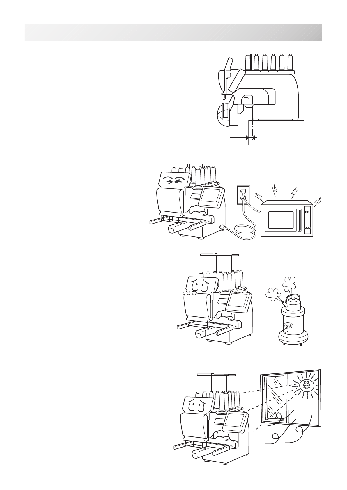
0 ~ 10 mm
4. Please be sure you have this much room around
your cap drive for it to move.
Please machine on the table positioning like right side
drawing.
5. Please do not sit the machine near any
kind of other electric equipment
(Examples: Microwave or electric tool).
Has possible to wrong movement of the ma-
chine.
6. Please keep away from dusty and high mois-
ture environments.
Has case of rusting or damaging.
7. Please do not sit the machine in direct sun-
shine or windy locations.
Has case of rusting or damaging.

-SA -12
Grounding instruction (for type of 120V)
This product must be grounded. In the event of malfunction or breakdown, grounding provides
a path of least resistance for electric current to reduce the risk of electric shock. This product is
equipped with a cord having an equipment-grounding conductor and a grounding plug. The plug
must be plugged into an appropriate outlet that is properly installed and grounded in accordance
with all local codes and ordinances.
DANGER – Improper connection of the equipment-grounding conductor can result in
a risk of electric shock. The conductor with insulation having an outer surface that is green with
or without yellow stripes is the equipment-grounding conductor. If repair or replacement of the
cord or plug is necessary, do not connect the equipment-grounding conductor to a live terminal.
Check with a qualied electrician or serviceman if the grounding instructions are not completely
understood, or if in doubt as to whether the product is properly grounded.
Do not modify the plug provided with the product – if it will not t the outlet, have a proper outlet
installed by a qualied electrician.
This product is for use on a nominal 120 V circuit, and has a grounding plug that looks like the
plug illustrated in sketch A in Figure. A temporary adaptor, which looks like the adaptor illustrated
in sketches B and C, may be used to connect this plug to a 2-pole receptacle as shown in sketch
B if a properly grounded outlet is not available. The temporary adaptor should be used only until
a properly grounded outlet can be installed by a qualied electrician. The green colored rigid ear,
lug, and the like, extending from the adaptor must be connected to a permanent ground such as
a properly grounded outlet box cover. Whenever the adaptor is used, it must be held in place by
the metal screw.
2_6 I916
2-7
SETTING UP THE MACHINE
Disposal of a battery
A battery is had built-in to this embroidery machine.
When you dispose of a battery, according to each country or a method determined in each area,
please dispose appropriately.
Metal screw
Cover of grounded
Grounding
Grounding
Grounding methods
Adapter
AB
C

-SA -15
1
2
3
4
5
6
7
8
9
10
11
12
13
15
16
17
18
23
24
25
26
27
14
21
19
22
20
1. Hook cover
2. Bobbin case
3. Hook
4. Needle plate
5. Thread check spring
6. Take-up lever cover
7. Take-up lever
8. Lowerrectier
9. Thread tension
10. Detecting roller
11. Minor thread tension
12. Thread guide support
13. Thread guide
14.Upperrectier
15. Thread stand pin
16. Thread stand felt
17. Thread stand
18. Needle bar selection knob
19. Control box
20. USB port
(Standard-B receptacle)
21. USB port
(Standard-A receptacle)
22. LAN port
23. Frame base
24. Carriage
25. Fuse (6A)
26. Terminal box
27. Power switch
When turning off the machine, be sure
to press (Power off) key on the
control box to turn off the machine.
5-1c
MAIN PARTS
3_1 UC01
3-1
CAUTION
Do not charge your smartphone etc via the USB port
(Standard-A
receptacle)
.
If you make a mistake, you can not operate the control box or can
not read from the USB port.
In this cace disconnect the USB cord and turn it back on once.
-SA -163_2 M717
3-2
MAIN PARTS
28. 糸糸糸糸
29. 糸糸糸糸糸糸
30. 糸糸糸
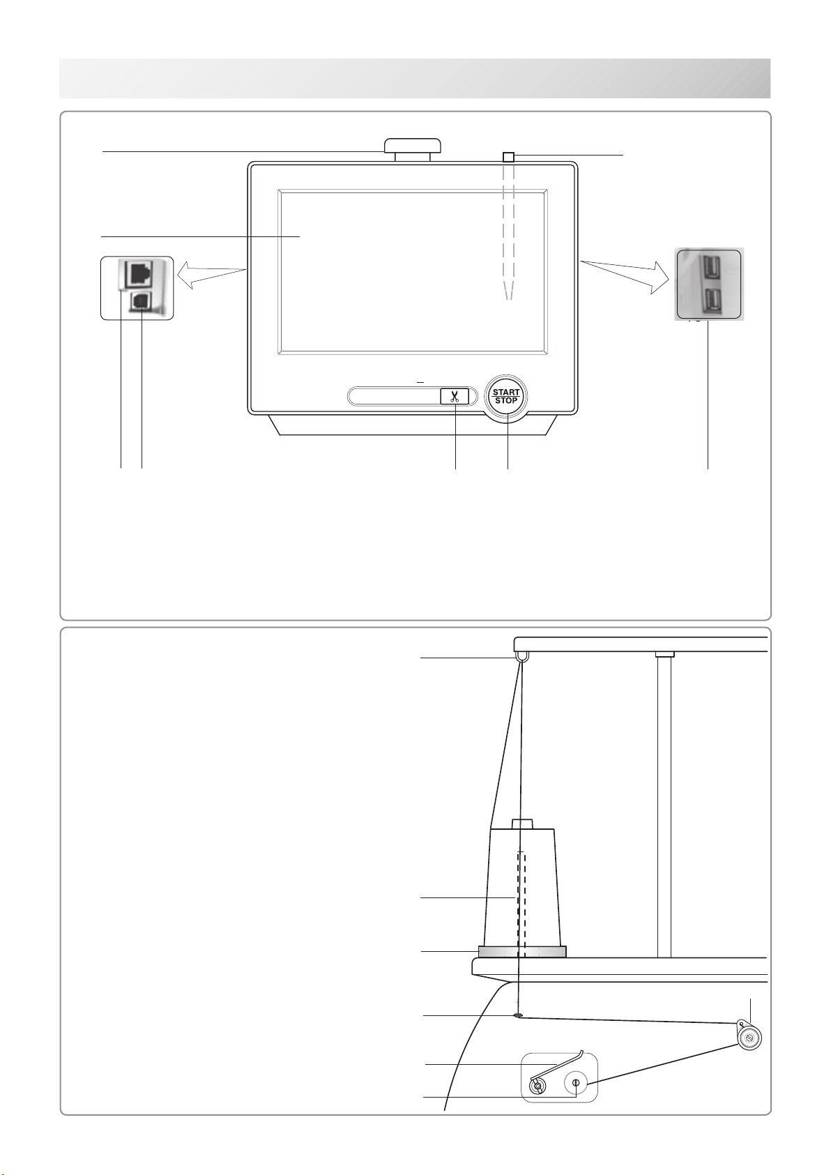
BOBBIN WINDING
7
5
6
1
4
2
3
1. Upper Thread guide
2. Thread stand pin
3. Thread stand felt
4. Thread guide
5. Thread tension
6. Spindle
7. Lever
CONTROL BOX
45
1. Emergency stop button
2. Display (L.C.D.)
3. LAN port
4. Thread cut button
5. Start/Stop button
6
37
1
2
16
8
6. USB port (Standard-A receptacle)
7. USB port (Standard-B receptacle)
8. Stylus

-DA .-21
1. Emergency stop button
When pressed , the power is switched off
and the machine stops immediately.
The emergency button locks when
pressed.
To unlock, turn the button to the right, or
pull it up.
Use this button only for emergency.
2. Display (Touch screen)
Shows the embroidery design name, the number
of the current needle and other machine generated
messages.
Menu and keys in the display can be operated with
a nger or built-in stylus.
3. LAN port
You can connect PC with a LAN.
4. Thread trim button
The Machine will cut the upper and lower thread
when this button is pressed.
In case you press and keep (around 2 sec.), you
can cut only bobbin thread.
THE CONTROL BOX
3_8 RC01
3-3
5. Start/Stop button
This button starts the machine.
When pressed, while the machine is running, the
machine will stop.
Green .......... Machine ready to sew.
Main menu also accessible by
pressing MENU, which causes menu
to display.
Blinking red.. Indicates the upper thread has bro-
ken or the Bobbin thread has run out.
Red.............. Machine is running.
Orange ........ Machine has detected an error.
An error number will be shown on
the Display. 24-1
6. USB port (Standard-A receptacle)
USB ash drive socket.
USB mouse socket.
Menu and keys in the display can be operated with
a commercial USB mouse.
Press right mouse button to show a mouse pointer
in the display.
7. USB port (Standard-B receptacle)
Use this port to connect the machine with PC via
USB.
8. Stylus
Stylus can be used for pressing menu and keys in
place of ngers.
Most operation can be done by ngers. Stylus is
required for some operation such as calibration for
the touch panel LCD. 18-6
Insert a stylus into the holder (slot) of control box
when not used to prevent loss of the stylus.
CAUTION: To prevent accidents.
If you Press thread trim button, the needle will
penetrate the fabric. Please keep your hands
clear for your safety.
1
2
45
1. Emergency stop button
2. Display (L.C.D.)
3. LAN port
4. Thread cut button
5. Start/Stop button
6. USB port
6
16
7
3
8
CAUTION
The touch screen can be operated by nger, but in some cases sensitivity of the screen will
be affected by condition of the nger.
In such cases, please use the ngertip or built-in stylus to hit small touch targets.
-S3 -30
3_9 U901
3-
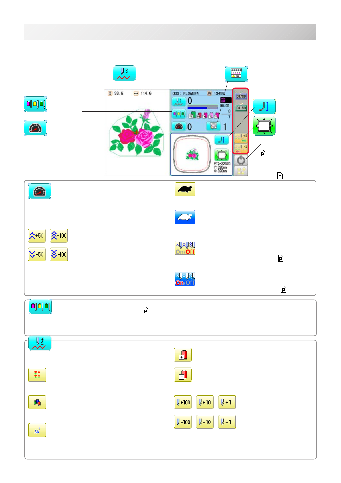
DRIVE MODE
Drive key
The each key menu will be shown.
Frame forward
This creates direct designations to the position and
data to the designated sewing position.
Piece
If “Repeat” is set, this allows the frame to move to
the beginning of any piece at will.
Change (Color position )
This moves the frame to the beginning of any Color
change number at will beginning of color.
Stitch (Number of stitches )
This moves the frame to any stitch at will.
Frame forward
Needle bar
selection
Drive speed
Needle change
Frame move
i-Custom
(default display)
Pressure foot
Drive speed
Control embroidery speed.
The speed can be controlled while embroidering.
Speed control
Press the + button to increase the machine sewing
speed and the - button to lower the machine speed.
is displayed on the LCD display.
Low speed operation (OFF state)
Press the button to turn “ON” state.
Low speed operation (ON state)
The drive speed will be reduced to “200 rpm”.
Press the button to turn “OFF” state.
Speed setting by needle (OFF state)
Press the button to turn “ON” state. 3-9d
Speed setting by needle (ON state)
Press the button to turn “OFF” state. 3-9d
Needle bar selection 5-E
For each color change in a given pattern, the needle number loaded with the correct color thread is as-
signed by the operator.
Color position forward
Move the frame to the beginning embroidery posi-
tion of the previous or later color position number
Stitch number forward
Move the frame forward or backward by the stitch
number displayed in each button.
Menu
Display menu
mode. 3-A
Powe off
Turn off the machine.
5-1c

-SA -21
3_9b Q701
3-5
DRIVE MODE
Needle change
Change
Change the needle bar directly to the indicated
needle number on the button.
Change
Move the sewing head to the adjacent needle in
the direction of the arrows.
Although the needl bar setting has been done,
needle bar setting is changed and pressed
, following dialogue will be displayed.
Needle bar setting will be changed and
the display will return to Drive mode.
Needle bar setting will not be changed
and the display will return to Drive mode.
Pressure foot
You can raise or lower the presser foot .
Jump (Off)
The machine can embroider.
Jump (On)
Mchine becomes jump and the machine doesn’t
embroider.

-SJ -28
3_9c SC01
3-6
DRIVE MODE
Original point return
This returns the frame to *pattern origin point.
After performing this action once, repeating this
again will cause the frame to return to the previous
position.
Origin registration
Register the current frame position as origin.
Trace
When pressed while at the beginning of design,
the embroidery frame moves following the outer
edge of the design. This allows you to compare
the design size and position against the frame
before sewing.
Register
Register will restore the position of the frame to the
last point before a power failure even if the
point of origin or the pattern itself were changed.
Frame move
Selection the way of frame movement and
Move frame.
Frame change
3-8a
Change the frame to be used.
Design centering
Move design to the center of frame.
Center
Moves the embroidery frame to the center auto-
matically.
Frame out
Move frame to the front position which was set on
the Machine setting ( 15-1b) before.
Press (Position) to return the frame to the
original position before frame out position.
It is convenience if hand work is required in the
middle of embroider process.
Position
When sewing is interrupted in the middle of a
design, this returns the frame to current sewing
position regardless of where frame may have
been moved with the arrow keys after interrupt.
target design.
i-Custom 22-1
The following display and key icons are set as default. You can place other frequently used icons freely on
the right side of Drive mode screen.
Calendar
Current year, month date is displayed.
Clock
Current time is displayed.
Stitch number forward
Move the frame forward or backward by the
one stitch.
In addition, “Key lock” function can be used by
setting. 15-2
When the key is pressed continuously, the “Key
lock” function is activated and the frame will move
continuously even the nger is released from the
key.
When the key is pressed much longer, the step of
“Stitch number forward” will be changed from one
stitch to 10 stitches.
When you stop it, press (Start/Stop button).

-SJ -26
3_9c NB01
Quick move
First press this key and then the arrow key to
move the frame toward the edge of the max-
imum embroidery area in the direction of the
arrow.
Quick embroidery design data position move
First press this key and then the arrow key to
move the frame where the design data can be
embroidered at the edge in the direction of the
arrow.
Frame move key
The frame moves toward direction of the arrow
3-7
DRIVE MODE
Pointer (Option)
Turn on and off the laser pointer.
Position alignment by dening 2 points
9-8
machine automatically sets angle and embroidery
only by dening 2 points.
X Direction frame move
YDirection frame move
The frame can be moved with specied distance
along X axis or Y axis. (Unit: mm)
The function allows you to move the frame pre-
cisely with a pitch of 0.1mm.
Select the number, and press .
The frame will move specied distance.
Changing is cancelled.
Numbers are deleted.
Pressure foot
You can raise or lower the presser foot .
Fast move (OFF state)
Press the button to turn “ON” state.
Fast move (ON state)
Press this key one time to move the frame faster
toward the direction of the arrow.
Press the button to turn “OFF” state.
Fast move speed setting (High)
Fast move speed setting (Middle)
Fast move speed setting (Low)
The speed of “Fast move” can be adjusted.
You can move the
embroidery frame
by pressing desired
position on the
screen.
Table of contents
Other HappyJapan Sewing Machine manuals


 User manual")


