Harbinger HA1000 User manual

OWNER’S
MANUAL
2 X 500
WATTS
HA1000 POWERED
MIXER
10
INPUTS
BUILT IN
DSP
®
BAL BAL BALBAL
www.harbingerproaudio.com

Owner’s Manual for the HA1000 Powered Mixer
2
Welcome
Your new PA includes:
• 2x500WoutputpowerwithStereo,Main/Monitor,orBridge
Monooperation
• 6Mic/LineinputswithXLRand¼”inputconnectors,plus12V
phantompower
• 4MicinputswithXLRandDual¼”inputconnectors
• Built-in24-bitDSPprocessorwith100presets
• Two9-bandGraphicEqualizers
• DualfunctionFX/Auxsendperchannel
• 3-bandEQperchannel
• Levelcontrolandbi-colorSignal/PeakLEDperchannel
• StereoOutputforrecording,StereoInputforCD/MP3playback
MonitorSendperchannel
ThankyouforyourpurchaseofthisHarbinger®PoweredMixer.
It’s packed with quality features usually found only on larger,
moreexpensivesystems.TogetthemostfromyournewHA1000,
takeamomentandreadthroughthisentiremanualtolearnabout
allitsimportantfeatures.
www.harbingerproaudio.com 3
DANGER
Exposuretoextremelyhighnoiselevelsmaycause
permanenthearingloss.Individualsvaryconsiderably
tonoise-inducedhearinglossbutmostwilllosesome
hearingifexposedtointensenoiseforasufcient
periodoftime.
TheU.S.Government’sOccupationalSafetyandHealth
Administration(OSHA)hasspeciedthefollowing
permissiblenoiselevelexposures:
AccordingtoOSHA,anyexposureintheabovepermissible
limitscouldresultinsomehearingloss.Earplugsor
protectorsintheearcanalorovertheearsmustbeworn
whenoperatingthisamplicationsysteminordertoprevent
apermanenthearingloss.Ifexposureinexcessofthelimits
asputforthabove,toinsureagainstpotentiallyharmful
exposuretohighsoundpressurelevels,itisrecommended
thatallpersonsexposedtoequipmentcapableofinducing
highsoundpressurelevels,suchasthisamplication
system,beprotectedbyhearingprotectorswhilethisunitis
inoperation.
THIS SYMBOL IS INTENDED TO ALERT THE USER TO THE PRESENCE
OF NON-INSULATED “DANGEROUS VOLTAGE” WITHIN THE
PRODUCT’S ENCLOSURE THAT MAY BE OF SUFFICIENT MAGNITUDE
TO CONSTITUTE A RISK OF ELECTRIC SHOCK TO PERSONS
THIS SYMBOL IS INTENDED TO ALERT THE USER TO THE PRESENCE
OF IMPORTANT OPERATING AND MAINTENANCE (SERVICING)
INSTRUCTIONS IN THE LITERATURE ACCOMPANYING THE UNIT.
APPARATUS SHALL NOT BE EXPOSED TO DRIPPING OR SPLASHING
AND THAT NO OBJECTS FILLED WITH LIQUIDS, SUCH AS VASES,
SHALL BE PLACED ON THE APPARATUS.
IMPORTANTSAFETYINSTRUCTIONS
1.Readallsafetyandoperatinginstructionsbeforeusing
thisproduct.
2.Allsafetyandoperatinginstructionsshouldbekeptfor
futurereference.
3.Readandunderstandallwarningslistedonthe
operatinginstructions.
4.Followalloperatinginstructionstooperatethisproduct.
5.Thisproductshouldnotbeusednearwater,i.e.abathtub,
sink,swimmingpool,wetbasement,etc.
6.Useonlyadryclothtocleanthisproduct.
7.Donotblockanyventilationopenings.Theproductshouldnot
beplacedatagainstawallorplacedinabuilt-inenclosure
thatwillimpedetheowofcoolingair.
8.Donotinstallthisproductnearanyheatsources,such
asradiators,heatregisters,stovesoranyotherapparatus
(includingheat–producingampliers)thatproducesheat.
9.Donotdefeatthesafetypurposeofthepolarizedor
grounding-typeplug.Apolarizedplughastwobladeswith
onewiderthantheother.Agrounding-typeplughastwo
bladesandathirdgroundingprong.Thewidebladeorthe
thirdprongareprovidedforyoursafety.Iftheprovidedplug
doesnottintoyouroutlet,consultanelectricianfor
replacementoftheobsoleteoutlet.
10.Protectthepowercordbeingwalkedonorpinched,
particularlyatplugs,conveniencereceptaclesandthepoint
wheretheyexitfromtheapparatus.Donotbreaktheground
pinofthepowersupplycord.
11.Onlyuseattachmentsspeciedbythemanufacturer.
12.Whenacartisused,usecautionwhenmoving
cart/apparatuscombinationtoavoidinjury
fromtip-over.
13.Unplugthisapparatusduringlightning
stormsorwhenunusedforlongperiodsoftime.
14.Careshouldbetakensothatobjectsdonot
fallandliquidsarenotspilledintotheunitthrough
theventilationportsoranyotheropenings.
15.Referallservicingtoaqualiedserviceprofessional.Servicing
isrequiredwhentheapparatusdoesnotoperatenormallyor
hasbeendamagedinanyway,includingdamagetothepower
cordorplug,damageduetoliquidsspilledorobjectsdropped
insidetheunit,droppingtheunit,oranythingelsethatinterrupts
normaluseoftheunit.
16.WARNING:Toreducetheriskofreorelectricshock,donot
exposethisapparatustorainormoisture.
17.ProtectiveGroundTerminal.Theapparatusshallbe
connectedtoanACmainsocketwithaprotectiveearthground
connection.
Important Safety Instructions
DURATION PER DAY (HOURS) 8 6 4 3 2 1
SOUND LEVEL (dB) 90 93 95 97 100 103

Owner’s Manual for the HA1000 Powered Mixer
4
Table of Contents
Basic Operation
Welcome..............................................................................2
Safety....................................................................................3
BasicOperation...................................................................4
FrontandRearPanelDiagram...........................................5
FrontPanelConnections......................................................6
FrontPanelControls............................................................7
RearPanelConnections......................................................10
Specications....................................................................... 11
BlockDiagram.....................................................................12
Warranty..............................................................................13
• Ensure the HA1000’s power is turned off.
• PlacetheHA1000ontheoor,atable,orasturdystand.
• TurndownallLevel,MonitorLevel,andMainLevelControls.
• Plugspeakersintotherearpanelspeakerjacks.
NOTE: Speakers should be placed in a location that
allows for unobstructed (line-of-sight) sound projection to
the audience. In many venues, it is beneficial to place
speakers on speaker stands for best results.
• Plugsourcessuchasmicrophones,instruments,orCD/MP3
playersintothefrontpaneljacks.
• TurnACPowerswitchto“On”.
• PluginallACconnectionsforsoundsystemandsources.
• SlowlyturntheMainLevelto12o’clock.
• SlowlyturntheLevelcontroloneachinputChanneluptothe
desiredvolumelevel.
www.harbingerproaudio.com
5
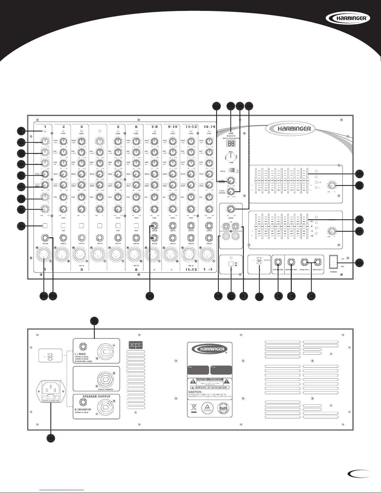
Front And Rear Panel Diagrams
14 CHANNEL • DSP • 2 X 500 WATTS
HA1000
0
CLIP
63
123
250
500
1K
2K
4K
0
+9
9
+15
15
0
CLIP
30
10
-
-
0
+9
9
+15
15
0
+9
9
+15
15
8K
16K
63
123
250
500
1K
2K
4K
0
+9
9
+15
15
0
0
0
0
+9
+9
+9
+9
9
9
9
9
15
15
15
15
8K
16K
30
10
1101
L
EVEL
LEVEL
POWER
AMPLIFIER
ASSIGN
PHANTOM
POWER 12V
PUSH TO SELECT
DSP
PROGRAM
OUT
STEREO IN/OUT
PEAK
PEAK
LEVEL
PAD
MIC IN
MIC IN
LEVEL
PAD
LEVEL
PAD
MIC IN
MIC IN
MIC IN
MIC IN
MIC IN
LIN
E OUTS
R
R
L
ON
OFF
00-09 Vocal
10-19 Small Room
20-29 Large Hall
30-39 Echo
40-49
60-69 Plate
50-59 Flange + Verb
80-89 Rotary + GTR
90-99 Tremolo + GTR
Echo + Verb
70-79 Chorus + GTR
MONITOR
MAIN
10
10
12
15
15
L
10
10
10
15
15
CLIP
HIGH
12KHz
MID
2.5KHz
LOW
80Hz
PAN
HIGH
12KHz
HIGH
12KHz
4
1
2
4
5
7
-
7-7
8
9
-
10
1
3
-
1
4
BRIDGE
BRIDGE
MAIN R
M
MAIN L
MAIN
L
+
L+L
R
SPEAKER OUTPUT
250W@ 8 OHM
(4 OHM MIN. LOAD)
BRIDGE OUTPUT
1000W@ 8 OHM
(8 OHM MIN. LOAD)
BRIDGE MODE
CLASS 2 WIRING
CLASS 2 WIRING
HA1000
14
CHANNEL
•
DSP
•
2 X 500 WATTS
AMPLIFIER ASSIGN
CHECK
"AMPLIFIER ASSIGN"
SWITCH ON FRONT PANEL
AC INPUT: 120V~60Hz
FUSE: T12AL AC250V
RATED POWER
CONSUMPTION: 1300W
BRIDGE
BRIDGE
MAIN R
M
ONITOR
MAIN L
MAIN
L
+
L+L
R
C
US
LEFT/MAIN
+
-
OUTPUT 1
1
1
POS
NEG
MADE IN CHINA
1 2 3 4 5
19
21
20
22
6 7 8
28
24
25 26 18
27
29
23
30
MIC IN
00-09 Vocal
10-19 Small Room
20-29 Large Hall
30-39 Echo
60-69 Plate
50-59 Flange + Verb
80-89 Rotary + GTR
90-99 Tremolo + GTR
Echo + Verb
70-79 Chorus + GTR
AMPLIFIER
ASSIGN
PHANTOM
POWER 12V
10
12KHz
11
2.5KHz
12
80Hz
13
14
15
16
17
R
POWER
9
Owner’s Manual for the HA1000 Powered Mixer
6
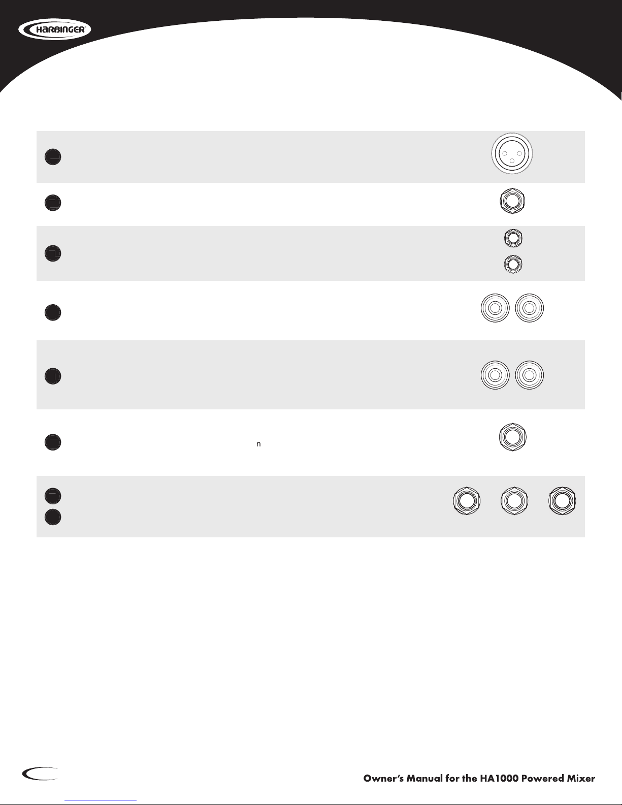
Front Panel Connections
XLR Mic In
put Jack Channel 1-14
Balanced.
Appr
opriate
f
or
micr
ophones,
or
dir
ect
connections
fr
om
am
pliers
or
DI
bo
xes.
¼” Line In
put Jack Channel 1-6
Balanced
or
Unbalanced.
Appropriate
for
instrument
or
line
level
equipment
connections.
Dual ¼” Line In
put Jack Channel 7-14
Balanced
or
Unbalanced.
Appropriate
for
instrument
or
line
level
equipment
connections.
Stereo Out
Unbalanced
dual
R
CA
outputs
f
or
connecting
t
o
MP3
r
ecorders
or
com
puters.
This
connection
has
a
xed
output
that
is
fed
from
the
MAIN
output.
S
tereo In
Unbalanced
in
puts
f
or
CD/MP3
pla
yers.
Use
eit
her
t
he
dual
R
CA
jac
ks
or
t
he
s
tereo
3.5mm
mini
jac
k.
These
in
puts
ar
e
contr
olled
b
y
t
he
S
tereo
In
Le
vel
contr
ol
and
ar
e
f
ed
t
o
the
Main
volume.
F
ootswitch DSP Mute
Plug
in
a
latc
hing
f
ootswitch
(no
t
included)
t
o
tur
n
t
he
DSP
Multi-FX
on/of
f
r
emotely.
Useful
to
turn
the
FX
off
when
talking,
and
back
on
when
singing/playing.
Monit
or Out/Main Out
Line
le
vel
output
contr
olled
b
y
t
he
Monit
or
or
Main
Le
vel
knob
t
o
send
t
he
signal
t
o
e
xternal
ampliers
or
powered
speakers.
Balanced
2
Balanced
Balanced
Balanced
Balanced
3
Balanced
Balanced
Unbalanced
Unbalanced
4
Unbalanced
Unbalanced
Unbalanced
5
Unbalanced
Unbalanced
Plug
Plug
6
Plug
Plug
7
Line
Line
8
Line
Line
Balanced.
Balanced.
Balanced.
Balanced.
Balanced.
Balanced.
1
PEAK
63 123 250 500 1K 2K 4K
0
+9
9
+15
15
0
+9
9
+15
15
8K 16K
63 123 250 500 1K 2K 4K
0
+9
9
+15
15
0
+9
9
+15
15
8K 16K
POWER
ON
OFF
PUSH TO SELECT
PROGRAM
24-BIT PROCESSOR
MULTI-FX
DSP
DSP
MUTE
CLIP
MUTE
1515
HIGH
12KHz
1212
MID
2.5KHz
1515
LOW
80Hz
10
MON
10
FX/AUX
POST
RL
PAN
RL
BAL
LEVEL
10
FX AUX
to MON
10
FX AUX
to MAIN
10
LEVEL
10
LEVEL
10
LEVEL
10
AMPLIFIER
ASSIGN
BRIDGEBRIDGE
MAIN R
MONITOR
MAIN L
MAIN L+R
MIC IN
21
3
LINE IN
LINE IN
FOOTSWITCH
MAIN OUT RMAIN OUT LMONITOR OUT
IN
RL
OUT
RL
PHANTOM
POWER 12V
ON
OFF

www.harbingerproaudio.com
7
9
Front Panel Controls
Signal/P
eak LED
This
This
9
This
9
This
This
LED
tur
ns
g
reen
when
a
signal
is
pr
esent
in
t
he
Mic/Line
in
put,
and
tur
ns
r
ed
when
t
he
input
signal
is
clipping.
If
this
occurs,
lower
the
source
signal
output
if
possible.
High EQ
This
is
t
he
tr
eble
contr
ol
used
t
o
boos
t
or
cut
high
fr
equencies
on
t
he
in
put
c
hannel,
using
a
high
shelf
lt
er
wit
h
+/-
1
5dB
of
boos
t
or
cut
abo
ve
1
2kHz.
Useful
f
or
adding
clar
ity
t
o
vocals
or
acoustic
guitars,
or
removing
hiss
or
unwanted
cymbal
pick-up.
Mid EQ
This
is
t
he
mid
r
ange
contr
ol
used
t
o
boos
t
or
cut
mid
fr
equencies
on
t
he
in
put
c
hannel,
using
a
band
lt
er
wit
h
+/-
1
2dB,
cent
ered
at
2.5kHz.
This
r
ange
will
af
fect
v
ocals
and
most
instruments.
Lo
w EQ
This
is
t
he
bass
contr
ol
used
t
o
boos
t
or
cut
lo
w
fr
equencies
on
t
he
in
put
c
hannel
using
a
low
shelf
lt
er
wit
h
+/-
1
5dB
of
boos
t
or
cut,
belo
w
80Hz.
Useful
f
or
r
emoving
r
umble
on
vocal
or
acoustic
guitar
inputs.
MON Send
This
contr
ol
sends
t
he
in
put
signal
t
o
t
he
Monit
or
Line
Out
jac
k
and
assigned
Monit
or
power
am
p
(speak
er
output
#2
when
MAIN
L+R
/
Monit
or
is
select
ed
in
t
he
Am
plier
Assign
section).
See
“Ampliers
Assign
Switch”
on
page
9.
FX/A
ux Send
This
contr
ol
sends
t
he
in
put
signal
t
o
t
he
built-in
DSP
FX
pr
ocessor
and
t
he
A
ux
Send
jac
k
in
the
master
section.
This
controls
the
amount
of
FX
used
on
each
input
channel.
P
an Channel 1-6/Bal Channel 7-14
This
contr
ol
adjus
ts
t
he
balance
of
t
he
in
put
signal
be
tween
t
he
Lef
t
and
Right
outputs
when
the
Amplier
Assign
is
MAIN
L
/
MAIN
R.
See
“Ampliers
Assign
Switch”
on
page
9.
Channel Le
vel
This
is
the
volume
control
for
individual
input
channels.
In
put Pad Channel 1-6
Reduces
t
he
in
put
signal
b
y
-20dB.
Useful
when
t
he
in
put
signal
is
v
ery
s
trong
and
overdriving
the
input
(causing
the
clip
light
to
constantly
ash
or
remain
lit).
PEAK
63 123 250 500 1K 2K 4K
0
+9
9
+15
15
0
+9
9
+15
15
8K 16K
63 123 250 500 1K 2K 4K
0
+9
9
+15
15
0
+9
9
+15
15
8K 16K
POWER
ON
OFF
PUSH TO SELECT
PROGRAM
24-BIT PROCESSOR
MULTI-FX
DSP
DSP
MUTE
CLIP
MUTE
1515
HIGH
12KHz
1212
MID
2.5KHz
1515
LOW
80Hz
10
MON
10
FX/AUX
POST
RL
PAN
RL
BAL
LEVEL
10
FX AUX
to MON
10
FX AUX
to MAIN
10
LEVEL
10
LEVEL
10
LEVEL
10
AMPLIFIER
ASSIGN
BRIDGEBRIDGE
MAIN R
MONITOR
MAIN L
MAIN L+R
MIC IN
21
3
LINE IN
LINE IN
FOOTSWITCH
MAIN OUT RMAIN OUT LMONITOR OUT
IN
RL
OUT
RL
PHANTOM
POWER 12V
ON
OFF
Reduces
Reduces
Reduces
Reduces
17
This
This
This
16
This
This
This
This
15
This
This
This
This
14
This
This
This
This
13
This
This
This
This
12
This
This
This
This
11
This
This
This
This
10
PAD

Owner’s Manual for the HA1000 Powered Mixer
8
S
tereo-In Level
This
is
t
he
v
olume
le
vel
f
or
an
y
de
vices
connect
ed
t
o
t
he
CD/MP3
in
puts
using
R
CA
or
mini-plug.
The
sound
from
CD/MP3
IN
goes
directly
to
the
MAIN
Output.
Monitor 9-Band Graphic EQ
Graphic
Eq
ualizer
cont
ains
9
lt
ers
t
hat
eac
h
cut
or
boos
t
+/-
1
5dB
ar
ound
t
heir
cent
er
frequency.
These
lt
ers
can
be
used
t
o
cont
our
t
he
o
verall
sound
of
all
in
puts,
and
r
educe
feedback
(cut
only).
The
EQ
assign
is
the
same
as
the
Amplier
Assign.
Monit
or Level
This
knob
contr
ols
t
he
output
le
vel
of
t
he
Monit
or
Out
jac
k.
Eac
h
in
put
Le
vel
contr
ol
f
eeds
both
the
Main
Out
(power
amp)
and
Monitor
Line
Out.
Main 9-Band Gr
aphic EQ
Graphic
Eq
ualizer
cont
ains
9
lt
ers
t
hat
eac
h
cut
or
boos
t
+/-
1
5dB
ar
ound
t
heir
cent
er
frequency.
These
lt
ers
can
be
used
t
o
cont
our
t
he
o
verall
sound
of
all
in
puts,
and
r
educe
feedback
(cut
only).
The
EQ
assign
is
the
same
as
the
Amplier
Assign.
Main Le
vel
This
knob
is
used
to
control
the
overall
output
level
delivered
to
the
speakers.
Phant
om On/Off
This
butt
on
is
used
when
condenser
micr
ophones
ar
e
connect
ed
t
o
t
he
HA1
000,
pr
oviding
12V
to
the
XLR
microphone
inputs.
Phantom
power
only
applies
to
XLR
input
connections.
PEAK
63 123 250 500 1K 2K 4K
0
+9
9
+15
15
0
+9
9
+15
15
8K 16K
63 123 250 500 1K 2K 4K
0
+9
9
+15
15
0
+9
9
+15
15
8K 16K
POWER
ON
OFF
PUSH TO SELECT
PROGRAM
24-BIT PROCESSOR
MULTI-FX
DSP
DSP
MUTE
CLIP
MUTE
1515
HIGH
12KHz
1212
MID
2.5KHz
1515
LOW
80Hz
10
MON
10
FX/AUX
POST
RL
PAN
RL
BAL
LEVEL
10
FX AUX
to MON
10
FX AUX
to MAIN
10
LEVEL
10
LEVEL
10
LEVEL
10
AMPLIFIER
ASSIGN
BRIDGEBRIDGE
MAIN R
MONITOR
MAIN L
MAIN L+R
MIC IN
21
3
LINE IN
LINE IN
FOOTSWITCH
MAIN OUT RMAIN OUT LMONITOR OUT
IN
RL
OUT
RL
PHANTOM
POWER 12V
ON
OFF
This
This
This
This
23
This
This
This
This
22
Graphic
Graphic
Graphic
Graphic
21
This
This
This
This
20
Graphic
Graphic
Graphic
Graphic
19
This
This
This
This
18
PEAK
63 123 250 500 1K 2K 4K
0
+9
9
+15
15
0
+9
9
+15
15
8K 16K
63 123 250 500 1K 2K 4K
0
+9
9
+15
15
0
+9
9
+15
15
8K 16K
POWER
ON
OFF
PUSH TO SELECT
PROGRAM
24-BIT PROCESSOR
MULTI-FX
DSP
DSP
MUTE
CLIP
MUTE
1515
HIGH
12KHz
1212
MID
2.5KHz
1515
LOW
80Hz
10
MON
10
FX/AUX
POST
RL
PAN
RL
BAL
LEVEL
10
FX AUX
to MON
10
FX AUX
to MAIN
10
LEVEL
10
LEVEL
10
LEVEL
10
AMPLIFIER
ASSIGN
BRIDGEBRIDGE
MAIN R
MONITOR
MAIN L
MAIN L+R
MIC IN
21
3
LINE IN
LINE IN
FOOTSWITCH
MAIN OUT RMAIN OUT LMONITOR OUT
IN
RL
OUT
RL
PHANTOM
POWER 12V
ON
OFF

www.harbingerproaudio.com
9
DSP Pr
ogram
This
knob
is
used
t
o
select
t
he
1
00
pr
eset
FX
pr
ograms
fr
om
t
he
built-in
2
4-bit
DSP
FX
processer.
Turn
the
knob
to
the
desired
FX
preset,
then
push
the
knob
to
select
the
effect.
DSP
24-BIT
FX
PRESET
TABLE
NO.
PRESET
PARAMETER
00-09
Vocal
Reverb
Delay
Time:
0.8
~
0.9s;
Pre-Delay:
0
~
45ms
10-19
Small
Room
Decay
Time:
07
~
2.1s;
Pre-Delay:
20
~
45ms
20-29
Large
Hall
Decay
Time:
3.6
~
5.4s;
Pre-Delay:
23
~
55ms
30-39
Echo
Delay
Time:
145
~
205s
40-49
Echo+Reverb
Delay
Time:
208
~
650ms;
Decay
Time:
1.7
~
2.1s
50-59
Flanger+Reverb
Decay
Time:
1.5
~
2.9ms;
Rate:
0.8Hz
~
2.5Hz
60-69
Plate
Decay
Time:
09s
~
3.6s
70-79
Chorus+GTR
Rate:
0.92Hz
~
1.7Hz
80-89
Rotary+GTR
Modulation
Depth:
20%
~
80%
90-99
Tremelo-GTR
Speed
FX t
o Monitor Level
This
contr
ol
sends
a
signal
fr
om
t
he
FX/A
ux
r
eturn
t
o
t
he
Monit
or
speak
ers
and
Monit
or
Line
Output.
FX to Main Level
This
contr
ol
sends
a
signal
fr
om
t
he
FX/A
ux
r
eturn
t
o
t
he
Main
speak
ers
and
Main
Line
Output.
P
ower On/Off
This
switc
h
tur
ns
t
he
HA1
000
on
and
of
f.
When
t
he
HA1
000
is
po
wered
on,
t
he
blue
Power
LED
will
light.
Am
plifiers Assign Switch
The
HA1000
features
2
separate
500-Watt
amps
MAIN L – MAIN R
•
Stereo
Mode
•
Output
1
is
Left
signal
•
Output
2
is
Right
signal
•
Monitor
outputs
to
Monitor
Out
jack
only
•
4Ω
minimum
speaker
load
per
output
MAIN L+R – MONIT
OR
•
Dual
Mono
Mode
•
Output
1
is
Main
•
Output
2
is
Monitor
•
4Ω
minimum
speaker
load
per
output
Br
idge – Bridge
•
Amplier
1
and
2
combine
into
a
single,
larger
amplier
(Mono)
•
Br
idge
Output
is
typicall
y
used
f
or
sub
woofer,
wit
h
Main
and
Monit
or
Line
Outputs
connect
ed
to
powered
speakers
•
8Ω
minimum
speaker
load
PEAK
63 123 250 500 1K 2K 4K
0
+9
9
+15
15
0
+9
9
+15
15
8K 16K
63 123 250 500 1K 2K 4K
0
+9
9
+15
15
0
+9
9
+15
15
8K 16K
POWER
ON
OFF
PUSH TO SELECT
PROGRAM
24-BIT PROCESSOR
MULTI-FX
DSP
DSP
MUTE
CLIP
MUTE
1515
HIGH
12KHz
1212
MID
2.5KHz
1515
LOW
80Hz
10
MON
10
FX/AUX
POST
RL
PAN
RL
BAL
LEVEL
10
FX AUX
to MON
10
FX AUX
to MAIN
10
LEVEL
10
LEVEL
10
LEVEL
10
AMPLIFIER
ASSIGN
BRIDGEBRIDGE
MAIN R
MONITOR
MAIN L
MAIN L+R
MIC IN
21
3
LINE IN
LINE IN
FOOTSWITCH
MAIN OUT RMAIN OUT LMONITOR OUT
IN
RL
OUT
RL
PHANTOM
POWER 12V
ON
OFF
This
This
This
This
25
This
This
This
This
26
This
This
This
This
27
The
The
The
28
PEAK
63 123 250 500 1K 2K 4K
0
+9
9
+15
15
0
+9
9
+15
15
8K 16K
63 123 250 500 1K 2K 4K
0
+9
9
+15
15
0
+9
9
+15
15
8K 16K
POWER
ON
OFF
PUSH TO SELECT
PROGRAM
24-BIT PROCESSOR
MULTI-FX
DSP
DSP
MUTE
CLIP
MUTE
1515
HIGH
12KHz
1212
MID
2.5KHz
1515
LOW
80Hz
10
MON
10
FX/AUX
POST
RL
PAN
RL
BAL
LEVEL
10
FX AUX
to MON
10
FX AUX
to MAIN
10
LEVEL
10
LEVEL
10
LEVEL
10
AMPLIFIER
ASSIGN
BRIDGEBRIDGE
MAIN R
MONITOR
MAIN L
MAIN L+R
MIC IN
21
3
LINE IN
LINE IN
FOOTSWITCH
MAIN OUT RMAIN OUT LMONITOR OUT
IN
RL
OUT
RL
PHANTOM
POWER 12V
ON
OFF
This
This
This
This
24
PEAK
63 123 250 500 1K 2K 4K
0
+9
9
+15
15
0
+9
9
+15
15
8K 16K
63 123 250 500 1K 2K 4K
0
+9
9
+15
15
0
+9
9
+15
15
8K 16K
POWER
ON
OFF
PUSH TO SELECT
PROGRAM
24-BIT PROCESSOR
MULTI-FX
DSP
DSP
MUTE
CLIP
MUTE
1515
HIGH
12KHz
1212
MID
2.5KHz
1515
LOW
80Hz
10
MON
10
FX/AUX
POST
RL
PAN
RL
BAL
LEVEL
10
FX AUX
to MON
10
FX AUX
to MAIN
10
LEVEL
10
LEVEL
10
LEVEL
10
AMPLIFIER
ASSIGN
BRIDGEBRIDGE
MAIN R
MONITOR
MAIN L
MAIN L+R
MIC IN
21
3
LINE IN
LINE IN
FOOTSWITCH
MAIN OUT RMAIN OUT LMONITOR OUT
IN
RL
OUT
RL
PHANTOM
POWER 12V
ON
OFF
Owner’s Manual for the HA1000 Powered Mixer
10
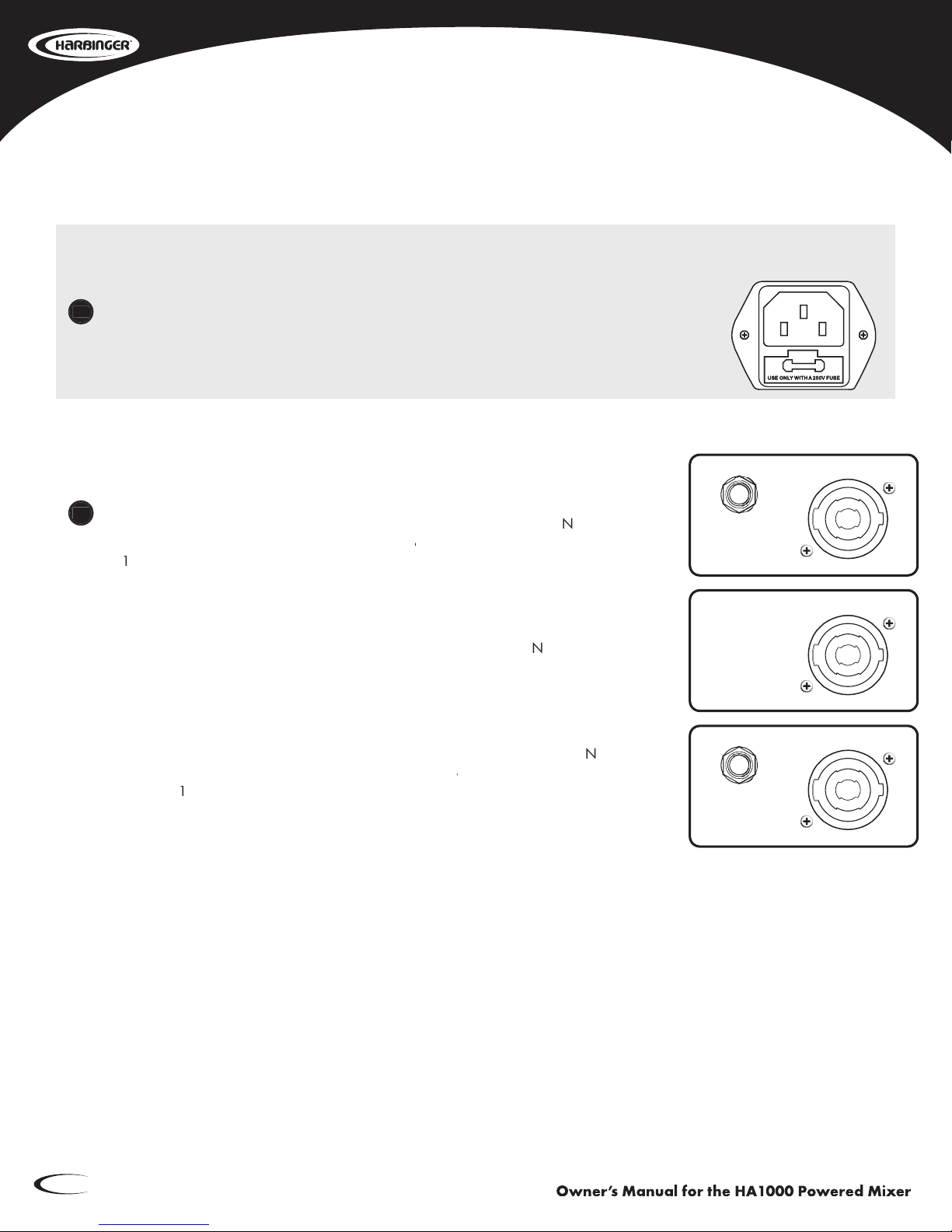
Rear Panel Connections
A
C Power Cord Input
This
is
t
he
A
C
Mains
connection.
Use
onl
y
t
he
supplied
IEC
cable
or
a
UL
lis
ted
r
eplacement
IEC
Cable
and
120V/60Hz
AC
outlet.
Speak
er Outputs
L/Main
Connect
up
t
o
tw
o
(2)
loudspeak
ers
t
o
t
he
speak
er
output
jac
ks.
N
ote
t
hat
t
he
HA1000
po
wer
am
p
is
r
ated
at
4Ω
Minimum
Load.
Y
ou
YouY
ma
y
saf
ely
connect
2
x
8Ω
speak
ers
or
1
x
4Ω
speaker.
Br
idge Output (Mono)
Connect
one
(1)
8Ω
speak
er
t
o
t
his
output.
N
ote
t
hat
damag
e
may
occur
to
the
HA1000
if
using
Bridge
Mode
with
more
than
one
8Ω
speaker.
R/Monitor
Connect
up
t
o
tw
o
(2)
loudspeak
ers
t
o
t
he
speak
er
output
jac
ks.
N
ote
t
hat
the
HA1
000
po
wer
am
p
is
r
ated
at
4Ω
Minimum
Load.
Y
ou
YouY
ma
y
saf
ely
connect
2
x
8Ω
speakers
or
1
x
4Ω
speaker.
N
ote: Twist-lock outputs are configured 1+ (pos)/1- (neg).
AMPLIFIER ASSIGN
CHECK
"AMPLIFIER ASSIGN"
SWITCH ON FRONT PANEL
BRIDGEBRIDGE
MAIN R
MONITOR
MAIN L
MAIN L+R
SPEAKER OUTPUT
L / MAIN
500W@ 4 OHM
250W@ 8 OHM
(4 OHM MIN. LOAD)
SPEAKER OUTPUT
R /MONITOR
500W@ 4 OHM
250W@ 8 OHM
(4 OHM MIN. LOAD)
BRIDGE OUTPUT
1000W@ 8 OHM
(8 OHM MIN. LOAD)
BRIDGE MODE
CLASS 2 WIRING
CLASS 2 WIRING
CLASS 2 WIRING
AC INPUT: 120V~60Hz
FUSE: T12AL AC250V
RATED POWER
CONSUMPTION: 1300W
This
This
This
This
29
30
www.harbingerproaudio.com 11
Power Amplifier (Output): (2x)500Watts
Input Channels MicrophoneInputs Electronicallybalanced,discreteinput
FrequencyResponse 20Hzto20kHz,±3dB
Gain 50dB
LineInputs Electronicallybalanced
FrequencyResponse 20Hzto20kHz,±3dB
Gain 20dB
Impedance MicrophoneInput 1.5kΩ
AllOtherInputs 10kΩorgreater
TapeOut 1kΩ
AllOtherOutputs 120Ω
Equalization HighShelving ±15dB@12kHz
MidShelving ±1[email protected]
LowShelving ±15dB@80Hz
GraphicEQ (2x)9-band,4/3Octave
DSP section A/DandD/AConverters 24-Bit
DSPResolution 24-Bit
TypeofEffects Vocal,SmallRoom,LargeHall,Echo,Echo+Reverb,
Flanger+Reverb,Plate,Chorus+GTR,Rotary+GTR
Presets 100
Controls 100-positionselector,ClipLED,MuteSwitchwithLED
indicator
Main Mix Section Noise(Busnoise) Fader0dB,channelsmuted=-85dBr(ref:+4dBu)
Fader0dB,allinputchannelsassignedand
settoUnityGain=-81dBr(ref:+4dBu)
MonitorMaxOut +22dBuunbalanced,1/4”jacks
FXSendsMaxOut +22dBuunbalanced,1/4"jacks
TotalHarmonicDistortion <0.5%@1Wattoutputpower;<1%@300Watt
output
SignaltoNoiseRatio Outputlineto1kHz=>65dB
StaticPowerConsumption Nooutputpowerstateat230V=<50Watts
PowerSource 110 ~127V/60Hz
Specifications

Owner’s Manual for the HA1000 Powered Mixer
12
12345678
A
B
C
D
8
7654321
D
C
B
A
3-STAGE EQ
LOW MID HI
_HA1000 BLOCK DIAGRAM
2
1
3
MIC IN
+12V
PHANTOM
-
+
POWER
3c
5e
1a
4d
2b
LINE IN
PAD
PEAK
+16dB=OL(GLOW)
SIG
PAN
LEVEL
FX/AUX
LEFT
RIGHT
MON
FX/AUX
MON
RIGHT BUS
FX/AUX BUS
MON BUS
LEFT BUS
3-STAGE EQ
2
1
3
MIC IN
+12V
PHANTOM
-
+
POWER
3c
5e
1a
4d
2b
LINE IN L
PEAK
+16dB=OL(GLOW)
SIG
BAL
LEVEL
FX/AUX
LEFT
RIGHT
MON
3-STAGE EQ
LOW MID HI
LEVEL
3c
5e
1a
4d
2b
LINE IN R
-
+
-
+
MON
FX/AUX
STEREO IN
-
+
-
+
LEFT
RIGHT
LEVEL
SUM
SUM
STEREO 9-STAGE EQ
50Hz
100Hz
250Hz
500Hz
1KHz
2.5KHz
5KHz
8KHz
16KHz
LEVEL
LEVEL
STEREO 9-STAGE EQ
3c
5e
1a
4d
2b
LINE OUT L
3c
5e
1a
4d
2b
LINE OUT R
SUM
LEVEL
MONO 9-STAGE EQ
50Hz
100Hz
250Hz
500Hz
1KHz
2.5KHz
5KHz
8KHz
16KHz
3c
5e
1a
4d
2b
MONITOR OUT
LED METERS
( 4 POINT )
LED METERS
( 4 POINT )
1+
1-
2+
2-
SPEAKER OUTPUT
LEFT/MAIN
1+
1-
2+
2-
SPEAKER OUTPUT
RIGHT/MONITOR
1+
1-
2+
2-
SPEAKER OUTPUT
BRIDGE
1
2
3
4
AMPLIFIER ASSIGN
1
2
3
4
INV
MAIN L
MAIN R
MONITOR
STEREO
AMPLIFIER
DSPFX/AUX
3c
5e
1a
4d
2b
DSP FOOTSWITCH
DSP MUTE
DSP SELECT
FX TO MON
FX TO MAIN
IN
OUT
LEFT
RIGHT
LEFT
RIGHT
MON
MON
RIGHT BUS
FX/AUX BUS
MON BUS
LEFT BUS
BA
BA
BA
BA
BA
BA
BA
BA

www.harbingerproaudio.com
13
Warranty
This
w
arranty
does
no
t
co
ver
ser
vice
or
par
ts
t
o
r
epair
damag
e
caused
b
y
neg
lect,
abuse,
normal
w
ear
and
t
ear
and
cosme
tic
appear
ance
t
o
t
he
cabine
try
no
t
dir
ectly
attr
ibuted
t
o
defects
in
mat
erials
or
w
orkmanship.
Also
e
xcluded
fr
om
co
verage
ar
e
damag
es
caused
directly
or
indir
ectly
due
t
o
an
y
ser
vice,
r
epair(s),
or
modications
of
t
he
cabine
t,
whic
h
have
no
t
been
aut
horized
or
appr
oved
b
y
Harbing
er.
This
tw
o
(2)
y
ear
w
arranty
does
no
t
cover
ser
vice
or
par
ts
t
o
r
epair
damag
e
caused
b
y
accident,
disas
ter,
misuse,
abuse,
bur
nt
voice-coils,
o
ver-powering,
neg
ligence,
inadeq
uate
pac
king
or
inadeq
uate
shipping
procedures.
The
sole
and
e
xclusive
r
emedy
of
t
he
f
oregoing
limit
ed
w
arranty
shall
be
limit
ed
to
t
he
r
epair
or
r
eplacement
of
an
y
def
ective
or
non-conf
orming
com
ponent.
All
w
arranties
including,
but
no
t
limit
ed
t
o,
t
he
e
xpress
w
arranty
and
t
he
im
plied
w
arranties
of
mer
chantability
and
tness
f
or
a
par
ticular
pur
pose
ar
e
limit
ed
t
o
t
he
tw
o
(2)
y
ear
w
arranty
per
iod.
Some
states
do
no
t
allo
w
limit
ations
on
ho
w
long
an
im
plied
w
arranty
las
ts,
so
t
he
abo
ve
limit
ation
may
no
t
appl
y
t
o
y
ou.
Ther
e
ar
e
no
e
xpress
w
arranties
be
yond
t
hose
s
tated
her
e.
In
t
he
e
vent
that
applicable
la
w
does
no
t
allo
w
t
he
limit
ation
of
t
he
dur
ation
of
t
he
im
plied
w
arranties
t
o
the
w
arranty
per
iod,
t
hen
t
he
dur
ation
of
t
he
im
plied
w
arranties
shall
be
limit
ed
t
o
as
long
as
is
provided
by
applicable
law.
No
warranties
apply
after
that
period.
Retailer
and
manuf
acturer
shall
no
t
be
liable
f
or
damag
es
based
upon
incon
venience,
loss
of
use
of
pr
oduct,
loss
of
time,
int
errupted
oper
ation
or
commer
cial
loss
or
an
y
o
ther
incident
al
or
consequential
damag
es
including
but
no
t
limit
ed
t
o
los
t
pr
ots,
do
wntime,
goodwill,
damag
e
to
or
r
eplacement
of
eq
uipment
and
pr
operty,
and
an
y
cos
ts
of
r
ecovering,
r
eprogramming,
or
reproducing
an
y
pr
ogram
or
dat
a
s
tored
in
eq
uipment
t
hat
is
used
wit
h
Harbing
er
pr
oducts.
This
guar
antee
giv
es
y
ou
specic
leg
al
r
ights.
Y
ou
YouY
ma
y
ha
ve
o
ther
leg
al
r
ights,
whic
h
v
ary
from
state
to
state.
Harbinger,
P.O.
Box
5111,
Thousand
Oaks,
CA
91359-5111
All
tr
ademarks
and
r
egistered
tr
ademarks
mentioned
her
ein
ar
e
r
ecognized
as
t
he
pr
operty
of
their
respective
holders.
Made
in
China
1110-9638
www.harbingerproaudio.com
S UND
ENGINEERING
www.harbingerproaudio.com
S UND
ENGINEERING
Harbinger Limited Warranty
Harbinger
provides
t
o
t
he
or
iginal
pur
chaser
a
tw
o
(2)
y
ear
limited
w
arranty
on
mat
erials
and
w
orkmanship
on
all
Harbing
er
cabinets
and
loudspeak
er
com
ponents
fr
om
t
he
dat
e
of
pur
chase.
If
y
our
co
vered
pr
oduct
is
def
ective,
ship
t
he
def
ective
component
t
ogether
wit
h
pr
oof
of
pur
chase
—
fr
eight
pr
epaid
and
insur
ed
—
t
o
an
A
uthorized
Harbing
er
r
epair
cent
er.
Please
contact
Harbing
er
Suppor
t
Headq
uarters
f
or
assis
tance
at
support@HarbingerProAudio.com,
or
visit
www.HarbingerProAudio.com.
A
R
eturn
A
uthorization
N
umber
mus
t
be
obt
ained
fr
om
our
Customer
Ser
vice
Depar
tment
pr
ior
t
o
shipping
t
he
pr
oduct.
To
locat
e
a
r
epair
cent
er
near
y
ou
and
t
o
obt
ain
a
R
eturn
A
uthorization
Number,
cont
act
support@HarbingerProAudio.com
or
visit
www.HarbingerProAudio.com.
2
So we may serve you better, please register
on-line at www.HarbingerProAudio.com

Table of contents
Other Harbinger Music Mixer manuals

Harbinger
Harbinger L2404FX-USB LvL series User manual

Harbinger
Harbinger L1202FX User manual

Harbinger
Harbinger LVL Series User manual

Harbinger
Harbinger LVL Seris User manual

Harbinger
Harbinger LVL Series User manual

Harbinger
Harbinger L1402FX-USB User manual

Harbinger
Harbinger L502 User manual

Harbinger
Harbinger LVL Series User manual

Harbinger
Harbinger LP9800 User manual


