Harbor Breeze E-AM54AI5LKL User manual

Federal regulations require ceiling fans with light kits manufactured or imported after
January 1, 2009, to limit total wattage consumed by the light kit to 190W. Therefore,
this fan is equipped with a wattage limiting device.
Questions, problems, missing parts? Before returning to your retailer, call or contact our
customer service department at 1-800-527-1292, 8:30 a.m. - 5:00 p.m., CST, Monday - Friday.
Harbor Breeze® is a registered trademark
of LF, LLC. All Rights Reserved.
ATTACH YOUR RECEIPT HERE
Serial Number Purchase Date
1
ITEM #0243307
MODEL #E-AM54AI5LKL
AUSTIN CEILING FAN
Español p. 19
E192641

TABLE OF CONTENTS
Safety Information ………………………………………………………...……..…...............2 - 3
Package Contents ……………………………………………………..……..…..…..................4
Hardware Contents ..................
....
........................................................................................
.........
5
Preparation ....….…………………..……………………….…………….……………............5
Initial Installation .........……………………...………………………………………
….
......6 - 7
Fan Mounting ..........…………………………………………………...................................7 - 8
Wiring ...................…………………….............................................………
......
.............9 - 10
Final Installation …………….……………………….…………….……..............
.…..
..........11 - 14
Operation Instructions .......................…………………………....................................14 - 15
Care and Maintenance ……………………………………………………………..……………........15
Troubleshooting .....………...………………………….……………..………......................16 - 17
Warranty ……………………………….…………………………………………..…..................17
Replacement Parts List .......................................................................................................
....
18
2
READ AND SAVE THESE INSTRUCTIONS
Please read and understand this entire manual before attempting to assemble, install or operate the
product. If you have any questions regarding the product, please call customer service at
1-800-527-1292, 8:30 a.m. - 5:00 p.m., CST, Monday - Friday.
• Do not discard fan carton or foam inserts. Should this fan need to be returned to the factory for
repairs, it must be shipped in its original packaging to ensure proper protection against damage that
might exceed the initial cause for return.
• Make sure that all electrical connections comply with local codes, ordinances, the National Electrical
Code and ANSI/NFPA 70-1999. Hire a qualified electrician or consult a do-it-yourself wiring handbook,
available at Lowe's, if you are unfamiliar with installing electrical wiring.
• Make sure the installation site you choose allows a minimum clearance of 7 feet from the blades to
the floor and at least 30 in. from the end of the blades to any obstruction.
• After you install the fan, make sure that all connections are secure to prevent the fan from falling.
• The net weight of this fan including the light kit is: 28.66 lbs. (13 kg).
SAFETY INFORMATION

3
To reduce the risk of fire, electrical shock, or personal injury, mount fan to outlet box
marked "ACCEPTABLE FOR FAN SUPPORT" and use mounting screws provided with
the outlet box. Most outlet boxes commonly used for the support of lighting fixtures are
not acceptable for fan support and may need to be replaced. Consult a qualified electrician if in
doubt. Secure the outlet box directly to the building structure. The outlet box and its support must
be able to support the moving weight of the fan (at least 35 lbs.). Do NOT use a plastic outlet box.
To avoid personal injury, the use of gloves may be necessary while handling fan parts with
sharp edges.
To reduce the risk of fire, electrical shock, or personal injury, wire connectors provided with this
fan are designed to accept only one 12 gauge house wire and two lead wires from the fan. If your
house wire is larger than 12 gauge or there is more than one house wire to connect to the two fan
lead wires, consult an electrician for the proper size wire connectors to use.
To reduce the risk of fire or electrical shock, do not use the fan with any solid state speed
control device or control fan speed with a full range dimmer switch.
To reduce the risk of fire, electrical shock, or personal injury, do not bend the blade arms when
installing them, balancing the blades, or cleaning the fan. Do not insert objects between the
rotating fan blades.
To reduce the risk of personal injury, use only parts provided with this fan. The use of parts
OTHER than those provided with this fan will void the warranty.
WARNINGS
CAUTIONS
Before proceeding, be sure to shut off electricity at main switch or circuit breaker in order to avoid
electrical shock.
Read all instructions and safety information before installing your new fan. Review the
accompanying assembly diagrams.
SAFETY INFORMATION

IMPORTANT REMINDER: You must
use the parts provided with this fan for
proper installation and safety.
PART DESCRIPTION QUANTITY
P
Motor Screw 10
(preassembled)
Q
5.4M/M
Lock Washer 10
(preassembled)
R Canopy Mounting Screw 2
(preassembled)
S
Pin (preassembled)
1
T
Clip (preassembled) 1
U
Socket Ring 3
(preassembled)
V Hex Nut (preassembled) 1
W Lock Washer
1
(preassembled)
PART DESCRIPTION QUANTITY
A
Downrod
2
B
Canopy 1
C
Mounting Bracket
1
D
Yoke Cover 1
E
Motor Housing
1
F Switch Housing Plate
1
G Light Kit Fitter
1
H
Switch Housing
1
I Shade 3
J
Blade Plate
5
K Blade Arm
5
L Blade
5
M Pull Chain Extension 2
N Candelabra Base Bulb 3
O Canopy Cover
1
PACKAGE CONTENTS
G
S
H
F
E
B
N
A
C
I
J
Q
P
T
D
M
U
R
O
K
L
V
W
4

HARDWARE CONTENTS (shown actual size)
AA
Blade
Screw
Qty. 15
5
Before beginning assembly and installation of product, make sure all parts are present. Compare
parts with package contents list and hardware contents above. If any part is missing or damaged, do
not attempt to assemble the product. Contact customer service for replacement parts.
Estimated Assembly Time: 120 minutes
Tools Required for Assembly (not included): Electrical Tape, Phillips Screwdriver, Pliers, Safety
Glasses, Stepladder and Wire Strippers
Helpful Tools (not included):AC Tester Light, Tape Measure, Do-It-Yourself Wiring Handbook
(available at Lowe’s), and Wire Cutters
Bulbs Required (included): 3 candelabra base 40-watt max. bulbs
DANGER: When using an existing outlet box, make sure the outlet box is securely attached to
the building structure and can support the full weight of the fan. Failure to do this can result in serious
injury or death. The stability of the outlet box is essential in minimizing wobble and noise in the fan
after installation is complete.
CAUTION: Be sure outlet box is properly grounded and that a ground wire (green or bare) is
present.
After opening top of carton, remove mounting hardware package from foam inserts. Remove motor
from packing and place on carpet or on foam to avoid damage to finish.
CAUTION: Carefully check all screws, bolts and nuts on fan motor assembly to ensure that they
are secured.
PREPARATION
CC
E3 Wire
Connector
Qty. 4
BB
Fiber
Blade
Washer
Qty. 15

INITIAL INSTALLATION
1
ON
OFF
ON
OFF
Turn off circuit breakers and wall switch to the fan
supply line leads. (Fig. 1)
DANGER: Failure to disconnect power supply
prior to installation may result in serious injury or
death.
1.
Determine mounting method to use. (Fig. 2)
A. Normal mount
B. Angle mount
Important: If using the angle mount, check to
make sure the ceiling angle is not steeper than 19°.
A
B
2. 2
Check to make sure blades (L) are at least 30 in.
from any obstruction. Check downrod (A) length to
ensure blades (L) are at least 7 ft. above the floor.
(Fig. 3)
7 ft.
min.
30 in.
min.
3
3.
Secure mounting bracket (C) to outlet box using
screws, spring washers, and flat washers
provided with the outlet box. (Fig. 4)
*Note: It is very important that you use the proper
hardware when installing the mounting bracket
(C) as this will support the fan.
IMPORTANT: If using the angle mount, make
sure open end of mounting bracket (C) is
installed facing the higher point of the ceiling.
4.
6
4Outlet
Box
C
L

INITIAL INSTALLATION
5. Remove motor screws (P) and 5.4M/M lock
washers (Q) from underside of motor and save for
blade arm (K) attachment later on. [If there are
plastic motor blocks installed with the motor
screws (P) and 5.4M/M lock washers (Q), discard
the plastic motor blocks.] (Fig. 5)
5
L
E
P
Q
FAN MOUNTING
1. 1
B
E
S
D
Choose downrod (A) length you wish to use.* If you
choose to use the 12 in. downrod (A), remove
hanging ball from the 6 in. downrod (A) and attach to
the 12 in. downrod (A). Insert downrod (A) through
canopy (B), canopy cover (O), and yoke cover (D).
(Fig. 2). [Note: Canopy cover (O) must be turned with
the shiny side toward the motor housing (E).] Thread
wires from motor housing (E) through downrod (A).
2
Hanging
Ball
2.
Slip downrod (A) into motor housing yoke, align
holes and re-install pin (S) and clip (T). Tighten
set screws and then tighten nuts. Slide yoke cover
(D) down until it rests on top of motor housing (E).
(Fig. 3) Set
Screw
A
3. 3
E
T
S
D
Set Screw
T
AO
Remove pin (S) and clip (T) from motor housing
yoke at top of motor housing (E) and partially loosen
set screws. (Fig. 1)
*Helpful Hint: Downrod style mounting is best
suited for ceilings 8 ft. (2.44 m) high or higher. For
taller ceilings you may want to use a longer downrod
(sold separately) than the ones provided. Angle style
mounting is best suited for angled or vaulted
ceilings. Longer downrods are sometimes necessary
to ensure proper blade clearance.
7

If you decided to cut back the lead wires in Step 4,
strip 1/2 of an inch of insulation from end of white
wire. Twist stripped ends of each strand of wire
within the insulation with pliers. (Fig. 5) Repeat
Step 5 for black, blue (if applicable) and green
wires.
5
5.
Depending on the length of downrod (A) you use,
you may need to cut the lead wires back to
simplify the wiring. If you decide to cut back the
lead wires, it is suggested that you do so in the
following manner:
Take the lead wires and make sure that you have
pulled them all the way through the top of the
downrod (A). Start at the TOP of the ball on the
downrod (A) and measure 8 in. of lead wire, and
then cut the excess wire off with wire cutters.
(Fig. 4)
NOTE: If you do not cut back the lead wires,
Steps 4 and 5 are not necessary and you may
proceed to Step 6 instead.
4.
Ball
A
D
4
FAN MOUNTING
Install ball end of downrod (A) into mounting
bracket (C) opening. Align slot in ball with tab in
mounting bracket (C). (Fig. 6)
DANGER: Failure to align slot in ball with tab
may result in serious injury or death.
6.
BBHanging
Ball Slot
A
6
Ball Tab
C
8

WIRING
9
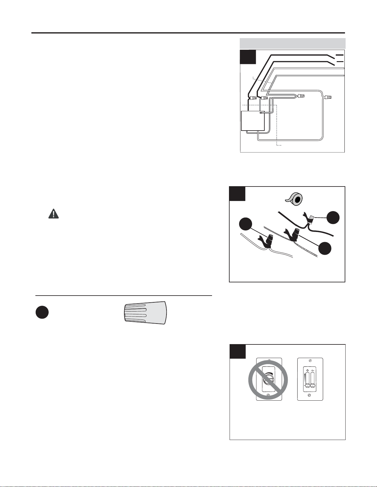
Choose wiring diagram (Fig. 1A, Fig. 1B or Fig. 1C)
that fits your situation and make appropriate wiring
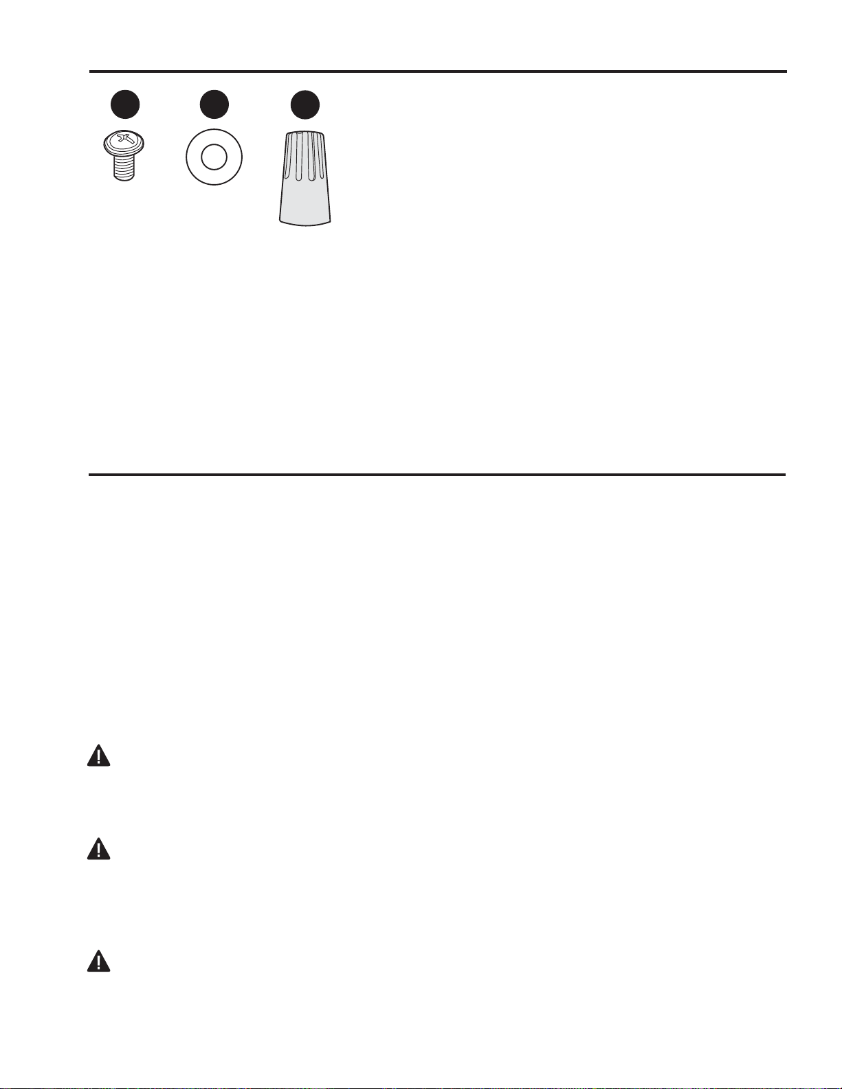
connections as follows: [NOTE: For each wire
connection below, use one of the wire connectors
(CC) provided, making sure to screw wire connector
(CC) on in a clockwise direction.]
1A. FAN AND LIGHT CONTROLLED BY PULL
CHAINS: Connect BLACK and BLUE wire from fan
to BLACK wire from ceiling. Connect WHITE wire
from fan to WHITE wire from ceiling. Connect all
GROUND (GREEN) wires together from fan (on
downrod and mounting bracket) to BARE/GREEN
wire from ceiling. (Fig. 1A)
1B. FAN CONTROLLED BY PULL CHAIN, LIGHT
BY WALL SWITCH: If you intend to control the fan
light with a separate wall switch, connect BLACK
wire from fan to BLACK wire from ceiling. Connect
BLUE wire from fan to the BLACK wire from the
independent wall switch for the light. Connect
WHITE wire from fan to WHITE wire from ceiling.
Connect all GROUND (GREEN) wires together
from fan (on downrod and mounting bracket) to
BARE/GREEN wire from ceiling. (Fig. 1B)
1.
FAN AND LIGHT CONTROLLED BY PULL CHAINS
BLACK
WHITE
GROUND/GREEN (BARE)
WHITE
BLUE
WHITE
FROM FAN
120 V Power
FROM
CEILING
FAN CONTROLLED BY PULL CHAIN, LIGHT BY
WALL SWITCH
WHITE
BLACK
BLACK (WALL SWITCH)
GROUND/GREEN (BARE)
BLACK
BLUE
WHITE
FROM FAN
FAN
120 V Power
FROM
CEILING
FAN
GREEN
GREEN
BLACK
WHITE
1A
1B
GREEN
GREEN
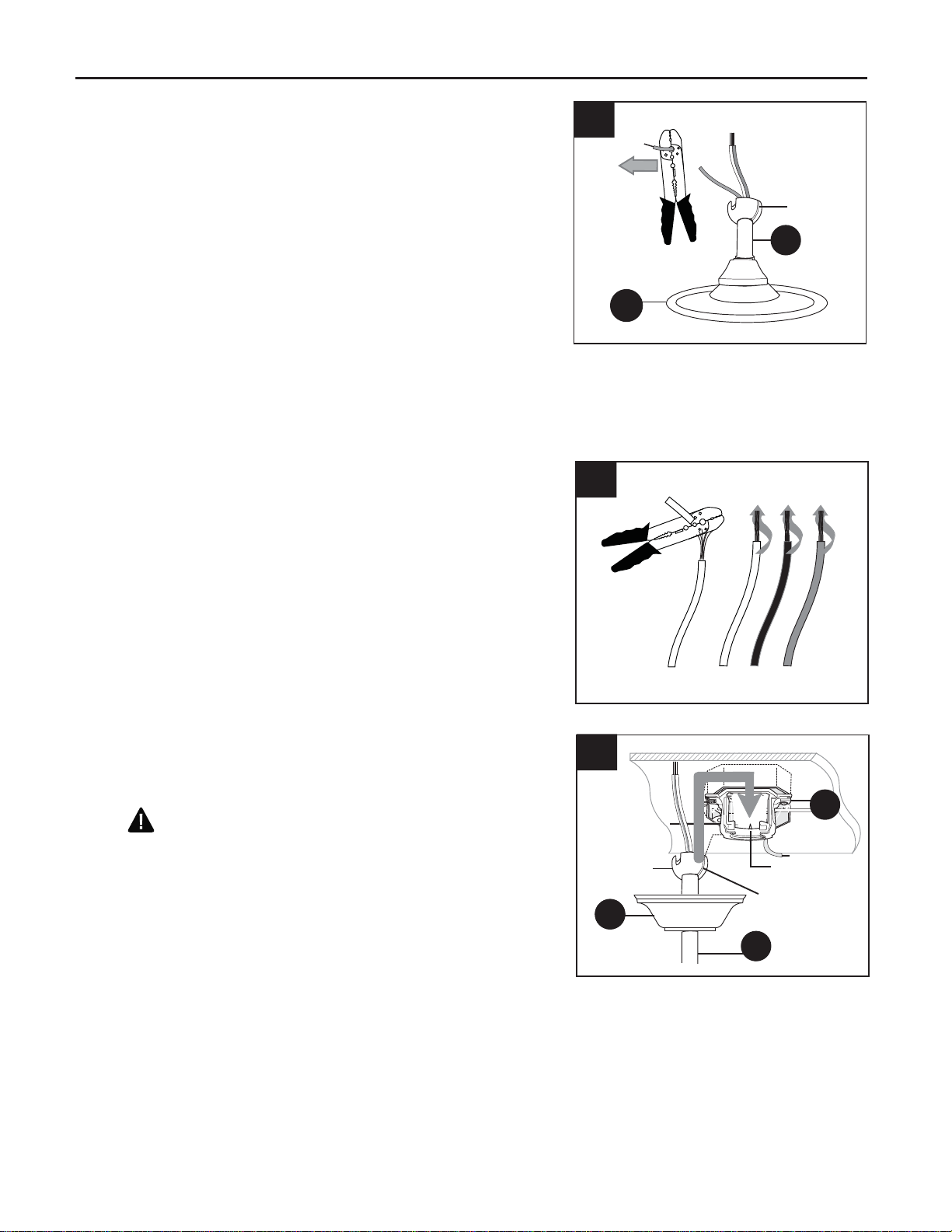
WARNING: To reduce the risk of fire, electrical
shock, or personal injury, wire connectors provided
with this fan are designed to accept only one 12
gauge house wire and two lead wires from the fan. If
your house wire is larger than 12 gauge or there is
more than one house wire to connect to the two fan
lead wires, consult an electrician for the proper size
wire connectors to use.
CAUTION: Be sure outlet box is properly grounded
and that a ground (green or bare) wire is present.
WARNING: If house wires are different colors
than referred to in the following steps, stop
immediately. A professional electrician is
recommended to determine wiring.

10
Wrap electrical tape around each individual wire
connector (CC) down to the wire as shown in Fig. 2.
WARNING: Make sure no bare wire or wire
strands are visible after making connections. Place
green and white connections on opposite side of box
from the black and blue (if applicable) connections.
Turn spliced/taped wires upward and gently push
wires and wire connectors (CC) into outlet box.
IMPORTANT: Using a full range dimmer switch to
control fan speed will cause a loud humming noise
from fan. To reduce the risk of fire or electrical
shock, do NOT use a full range dimmer switch to
control fan speed. (Fig. 3)
CC
CC
2
CC
CC E3 Wire Connector x4
3
1
2
3
Dimmer
Switch Speed
Switch
For illustrative purposes only--not
intended to cover all types of controls
2.
Hardware Used
3.
WIRING
1C. FAN AND LIGHT CONTROLLED BY TWO
WALL SWITCHES: If you intend to control the fan
and light with separate wall switches, connect
BLACK wire from fan to BLACK wire from the
independent wall switch for the fan. Connect BLUE
wire from fan to the BLACK wire from the other
independent wall switch for the light. Connect
WHITE wire from fan to WHITE wire from ceiling.
Connect all GROUND (GREEN) wires together
from fan (on downrod and mounting bracket) to
BARE/GREEN wire from ceiling. (Fig. 1C)
Note: Black wire is hot power for fan. Blue wire is hot
power for light kit. White wire is common for fan and
light kit. Green or bare wire is ground.
WHITE
BLACK (WALL SWITCH)
BLACK (WALL SWITCH FOR LIGHT)
GROUND/GREEN (BARE)
BLACK
BLUE
WHITE
FROM FAN
FAN
120 V Power
FROM
CEILING
FAN AND LIGHT CONTROLLED BY TWO WALL
SWITCHES
GREEN
WHITE
1C
GREEN

Hold blade (L) in between blade arm (K) and blade
plate (J) and align holes. Insert three blade screws
(AA), along with fiber blade washers (BB), with fingers
first and then tighten blade screws (AA) securely with
a Phillips screwdriver. (Fig. 2) Repeat for the
remaining blades (L).
Insert only one motor screw (P) through blade arm
(K) to attach blade arm (K) to motor using one of
the 5.4M/M lock washers (Q) and one of the motor
screws (P) that were previously removed (Step 5,
page 7). Partially tighten motor screw (P). (Fig. 3)
Repeat with remaining blade arms (K).
Insert remaining motor screws (P) with 5.4M/M
lock washers (Q). Tighten all motor screws (P)
securely.
FINAL INSTALLATION
1. Locate two canopy mounting screws (R) on underside of
mounting bracket (C) and remove canopy mounting
screw (R) closest to the open end of of the mounting
bracket (C). Partially loosen the other canopy mounting
screw (R). Lift canopy (B) to mounting bracket (C).
Place rounded part of slotted hole in canopy (B) over
loosened canopy mounting screw (R) in mounting
bracket (C) and push up. Twist canopy (B) to lock.
Re-insert canopy mounting screw (R) that was removed,
and then tighten both canopy mounting screws (R)
securely. Slide canopy cover (O) up to canopy (B),
aligning rounded part of slotted holes in canopy cover
(O) with screwheads in bottom of canopy (B). Turn
canopy cover (O) to the right (clockwise) until it stops.
(Fig. 1)
1
O
R
B
A
A
2
J
K
L
AA
BB
2.
K
E
Q
P
3
3.
11

Remove hex nut (V) and lock washer (W) from
threaded rod on light kit fitter (G). Gently feed
wires from light kit fitter (G) through center hole in
switch housing (H) and then through lock washer
(W) and hex nut (V). Secure switch housing (H) to
light kit fitter (G) by tightening the hex nut (V).
(Fig. 6)
If you wish to use the light kit, punch center cap
out of switch housing (H) with a screwdriver.
Locate BLUE and WHITE wires in switch housing
(H) labeled FOR LIGHT and remove plastic that
holds these two wires together. (Fig. 5)
If you do NOT wish to use the light kit, attach
switch housing (H) as described in Step 8 on the
following page.
Remove one screw from fitter plate (on underside
of motor) and loosen the other two screws. Align
slotted holes in switch housing plate (F) with
loosened screws in fitter plate. Twist switch housing
plate (F) to lock and re-install screw that was
previously removed. Tighten all screws securely.
(Fig. 4) Fitter
Plate
4E
F
4.
FINAL INSTALLATION
5.
6. 6
G
V
WH
Connect BLUE wire from switch housing (H)
to BLACK wire from light kit fitter (G).
Connect WHITE wire from switch housing (H)
to WHITE wire from light kit fitter (G). Be sure
molex connections snap together securely.
(Fig. 7)
WHITE
BLUE
BLACK
WHITE
Molex
Connections
GH
7Molex
Connections
7.
Center Cap
WHITE
BLUE
5
H
12

Remove three screws from switch housing plate (F).
Connect female plug from switch housing (H) to
male plug from motor housing (E), matching up the
colors on the male plug with the colors on the female
plug for correct fit.
Align holes in switch housing (H) with holes in switch
housing plate (F). Re-insert screws that were
previously removed and tighten all screws securely
with a Phillips screwdriver. (Fig. 8)
Note: If you are not using the light kit, please
proceed to Step 11 instead of continuing with Step 9.
FINAL INSTALLATION
8.
F
H
G
8
Remove socket rings (U) from sockets. Use these
socket rings (U) to attach shades (I) to light kit fitter
(G). (Fig. 9) 9
I
G
U
9.
Install three candelabra base 40-watt max. bulbs
(N) included. (Fig. 10)
Important: When you need to replace bulbs, please
allow bulb(s) and light kit fitter (G) to cool down
before touching them.
10
G
N
10.
13

The pull chain extensions (M) supplied in one
of the hardware packs or custom pull chain
extensions (sold separately) may be attached
to fan and/or light pull chains. (Fig. 11)
NOTE: This fan is remote control adaptable
(remote control sold separately).
11
M
11.
OPERATION INSTRUCTIONS
1.
2.
The pull chain on the switch housing (H) has four
positions to control fan speed. One pull is HIGH, two is
MEDIUM, three is LOW and four turns the fan OFF.
(Fig. 1)
The pull chain in the middle is used to turn the lights
ON or OFF. (Fig. 2)
1
2
FINAL INSTALLATION
14

3. Use the fan reverse switch, located on the switch
housing, to optimize your fan for seasonal
performance. (Fig. 3) A ceiling fan will allow you to
raise your thermostat setting in summer and lower
your thermostat setting in winter without feeling a
difference in your comfort.
Note: Wait for fan to stop before moving the
reverse switch.
Reverse
Switch
H
3
3A. In warmer weather, setting the reverse switch
to the LEFT will result in downward airflow
creating a wind chill effect. (Fig. 3A)
3B. In cooler weather, setting the reverse switch
to the RIGHT will result in upward airflow that
can help move stagnant, hot air off the ceiling
area. (Fig. 3B)
3C. IMPORTANT: Reverse switch must be set
either completely to the RIGHT or completely to
the LEFT for fan to function. If the reverse switch
is set in the middle position (Fig. 3C), fan will not
operate.
3A
3B
3C
OPERATION INSTRUCTIONS
At least twice each year, lower canopy (B) to check downrod (A) assembly, and then tighten all screws
on the fan. Clean motor housing (E) with only a soft brush or lint-free cloth to avoid scratching the finish.
Clean blades (L) with a lint-free cloth. You may occasionally apply a light coat of furniture polish to wood
blades for added protection.
Important: Shut off main power supply before beginning any maintenance. Do not use water or a damp
cloth to clean the ceiling fan.
CARE AND MAINTENANCE
15

TROUBLESHOOTING
If you have any questions regarding the product please call customer service at 1-800-527-1292,
8:30 a.m. - 5 p.m., CST, Monday - Friday.
Warning: Before beginning work, shut off the power supply to avoid electrical shock.
PROBLEM POSSIBLE CAUSE CORRECTIVE ACTION
Fan does not move. 1. Reverse switch not engaged. 1. Push switch firmly to the right or
to the left.
2. Power is off or fuse is blown. 2. Turn power on or check fuse.
3. Faulty wire connection. 3. Turn power off. Loosen canopy
(B) and check all connections.
4. Plugs not connected properly. 4. Check that male and female
plugs in switch housing (H) are
connected properly according to
instructions on page 13.
Noisy operation. 1. Blades (L) are loose. 1. Tighten all blade screws (AA).
2. Cracked blade (L). 2. Replace blade (L).
3. Full range dimmer switch. 3. Replace with an approved
speed control device.
4. Fan is new. 4. Allow fan a "break in" period of a
few days, especially when running
the fan at Medium and High
speeds.
Excessive wobbling. 1. Blades (L) are loose. 1. Tighten all blade screws (AA).
2. Blade arms (K) incorrectly 2. Re-install blade arms (K).
attached.
3. Unbalanced blades (L). 3. Switch one blade (L) with a
blade (L) from the opposite side.
4. Fan not securely mounted. 4. Turn power off. Carefully loosen
canopy (B) and verify that
mountingbracket (C) is secure.
5. Fan too close to vaulted ceiling. 5. Use a longer downrod (A) or
move fanto another location.
6. Set screw(s) on motor housing 6. Tighten yoke set screw(s)
yoke is (are) not tightened properly. securely.
7. Set screw on hanging ball is not 7. Carefully loosen and lower
tightened properly. canopy (B) and verify that set
screw on hanging ball is tightened
securely.
Fan operates but lights 1. Bulb(s) not installed correctly. 1. Re-install bulb(s).
fail. (if applicable). 2. Wires in canopy (B) not wired 2. Check wires in canopy (B) and,
properly. if necessary, re-wire according to
instructions on pages 9 and 10.
3. Wall switch to fan is off. 3. Make sure that wall switch to fan
is on.
16

WARRANTY
LIMITED LIFETIME WARRANTY: Litex Industries warrants this fan to be free from defects in
workmanship and materials present at time of shipment from the factory for Lifetime limited from the
date of purchase. This warranty applies only to the original purchaser. Litex Industries agrees to
correct any defect at no charge or, at our option, replace the ceiling fan with a comparable or
superior model.
To obtain warranty service, present a copy of your sales receipt as proof of purchase. All cost of
removal and reinstallation are the express responsibility of the purchaser. Any damage to the ceiling
fan by accident, misuse or improper installation, or by using parts not produced by the manufacturer
of this fan or affixing accessories not produced by the manufacturer of this fan, are the purchaser's
own responsibility. Litex Industries assumes no responsibility whatsoever for fan installation during
the limited lifetime warranty. Any service performed by an unauthorized person will render the
warranty invalid.
Due to varying climatic conditions, this warranty does not cover changes in brass finish, rusting,
pitting, tarnishing, corroding or peeling. Brass finish fans maintain their beauty when protected from
varying weather conditions. Any glass provided with this fan is not covered by the warranty.
Any replacement of defective parts for the ceiling fan must be reported within the first year from the
date of purchase. For the balance of the warranty, call our customer service department (at
1-800-527-1292) for return authorization and shipping instructions so that we may repair or replace
the ceiling fan. Any fan or parts returned improperly packaged is/are the sole responsibility of the
purchaser. There is no further express warranty. Litex Industries disclaims any and all implied
warranties. The duration of any implied warranty which cannot be disclaimed is limited to the limited
lifetime period as specified in our warranty. Litex Industries shall not be liable for incidental,
consequential or special damages arising at or in connection with product use or performance
except as may otherwise be accorded by law. This warranty gives you specific legal rights and you
may also have other rights which vary from state to state. This warranty supersedes all prior
warranties.
PROBLEM POSSIBLE CAUSE CORRECTIVE ACTION
4. Wires in switch housing (H) are 4. Check that male and female
not connected properly. plugs and molex connections in
switch housing (H) are connected
properly according to instructions
on page 12 and 13.
5. Original light kit has been re- 5. Replace with original light kit or
moved and the wattage surpasses lamp light kit with bulbs that total
the allowable 190W, causing the no more than 190W.
wattage limiting device to interrupt
the flow of electricity to the light kit.
6. Light kit is lamped with more 6. Lamp light kit with bulbs that
than the allowable 190W, causing total no more than 190W.
the wattage limiting device to
interrupt the flow of electricity to
the light kit.
Warning: Before beginning work, shut off the power supply to avoid electrical shock.
TROUBLESHOOTING
17

Printed in China
REPLACEMENT PARTS LIST
For replacement parts, call our customer service department at 1-800-527-1292, 8:30 a.m. - 5:00 p.m.,
CST, Monday - Friday. When ordering parts, please have the Model # or Item # of the fan available,
which can be found on page 1.
A
Downrod
B
Canopy
C
Mounting Bracket
D
Yoke Cover
F Switch Housing Plate
G Light Kit Fitter
H
Switch Housing
I Shade
J Blade Plate
K
Blade Arm
L Blade
M Pull Chain Extension
O Canopy Cover
P
Motor Screw
Q
5.4M/M
Lock Washer
R Canopy Mounting Screw
S
Pin
T
Clip
U
Socket Ring
V
Hex Nut
W
Lock Washer
AA
Blade Screw
BB Fiber Blade Washer
CC
E3 Wire Connector
PART DESCRIPTION
G
S
H
F
B
AC
IJ
Q
PT
D
M
U
R
O
KL
VWBB CC
AA
18

El reglamento federal requiere que un ventilador de techo con juego de luz fabricado o
importado después del 1ro de enero del 2009 limite el vatiaje total que consume el juego
de luz a 190W. Por lo tanto, este ventilador tiene un aparato que sirve para limitar el
vatiaje.
19
ARTICULO #0243307
MODELO #E-AM54AI5LKL
VENTILADOR DE TECHO AUSTIN
Harbor Breeze® es marca registrada de LF,
LLC. Reservados todos los derechos.
E192641
¿Preguntas, problemas, faltan piezas? Antes de regresar a la tienda, llame o póngase en
contacto con nuestro departamento de servicio al cliente al 1-800-527-1292, de 8:30 a.m. a
5:00 p.m., hora central, de lunes a viernes.
ADJUNTE SU RECIBO AQUI
Número de serie Fecha de compra

20
Información de seguridad …………………………………............................……...
…
…..
....
20 - 21
Contenido del paquete …………………………………………………………………..……........22
Contenido de artículos de ferretería ..........................................................................................23
Preparación ..............….…………………..……………………….…………….….........…........23
Instalación inicial .....................………………………………………………………
….
.......24 - 25
Montaje del ventilador ...................................................................................................25 - 26
Conexión de los cables ……………………………………….......………….................27 - 28
Instalación final ….…………….…….………………….……...…….……........................29 - 32
Instrucciones de funcionamiento ............................................……………………………
.....
32 - 33
Cuidado y mantenimiento ....……………………………………………………..……………....33
Localización de fallas ................…….......…………………………………..………....….....34 - 35
Garantía ..........………………………….………………………………………….……........…....36
Lista de piezas de repuestos ....................................................................................................37
POR FAVOR LEA Y GUARDE ESTAS INSTRUCCIONES
Por favor lea el instructivo entero antes de tratar de ensamblar, instalar o hacer funcionar el producto. Si
tiene alguna pregunta acerca del producto, por favor llame al servicio al cliente al 1-800-527-1292, de 8:30
a.m. a 5:00 p.m., hora central, de lunes a viernes.
• No deseche la caja del ventilador ni la goma espuma incluida. Si hay que mandar el ventilador a la
fábrica por alguna reparación, se debe enviar en su paquete original para asegurar la protección apropiada
contra daños que podrían exceder la causa inicial por la cual se devolvió.
• Asegúrese de que todas las conexiones eléctricas cumplen con los códigos y las ordenanzas locales, con
el Código Nacional Eléctrico (NEC, por sus siglas en inglés), y ANSI/NFPA 70-1999. Contrate un
electricista calificado o consulte una guía de instalación eléctrica de hágalo usted mismo, disponible en
Lowe's, si no está familiarizado con la instalación eléctrica.
• Asegúrese de que el lugar de instalación que usted escogió tiene un mínimo de 2,13 m de desde las
paletas hasta el piso y que la punta de las paletas quede a por lo menos 76,2 cm de cualquier obstrucción.
• Después de instalar el ventilador, verifique que todas las conexiones estén seguras para que no se caiga
el ventilador.
• El peso neto del ventilador con el juego de luz es de: 13 kg.
INDICE DE MATERIAS
INFORMACION DE SEGURIDAD
Table of contents
Languages:
Other Harbor Breeze Ceiling Fan manuals