Harbor Breeze CPJ1240 User manual

1
Español p. 19
BAY BRIDGE CEILING FAN
ITEM #0451817
MODEL #CPJ1240
Serial Number Purchase Date
Questions, problems, missing parts? Before returning to your retailer, call our customer
service department at 1-800-643-0067, 8 a.m. - 6 p.m., EST, Monday - Thursday,
8 a.m. - 5 p.m., EST, Friday.
EB14464
ATTACH YOUR RECEIPT HERE
Lowes.com/harborbreeze
Harbor Breeze®is a registered trademark
of LF, LLC. All Rights Reserved.

2
TABLE OF CONTENTS
Package Contents ...............................................................................................................
Hardware Contents .............................................................................................................
Safety Information ...............................................................................................................
Preparation ..........................................................................................................................
Initial Instructions..................................................................................................................
Standard/Angle-Mounting Instructions .................................................................................
Flushmount Instructions .......................................................................................................
Wiring Instructions ...............................................................................................................
Final Instructions .................................................................................................................
Operating Instructions .........................................................................................................
Care and Maintenance ........................................................................................................
Troubleshooting ...................................................................................................................
Limited Lifetime Warranty ....................................................................................................
Replacement Parts List .......................................................................................................
3
4
4
5
6
7
9
10
11
14
15
15
17
18
Lowes.com/harborbreeze

3
PACKAGE CONTENTS
Lowes.com/harborbreeze
PART DESCRIPTION QUANTITY
A Mounting Bracket 1
B Canopy 1
C Canopy Cover (preassembled on Canopy (B)) 1
D Downrod Assembly 1
E Coupling Cover 1
F Coupling (preassembled to Motor Housing (G)) 1
G Motor Housing 1
H Switch Housing (preassembled to Motor Housing (G)) 1
I Blade Iron 5
J Blade 5
K Light Kit 1
L Glass Bowl 3
M Bulb 3
N Clevis Pin (preassembled to Coupling (F)) 1
O Hairpin Clip (preassembled to Coupling (F)) 1
P Coupling Screw (preassembled to Coupling (F)) 2
Q Balance Kit 1
R Mounting Bracket Screw (preassembled to Mounting Bracket (A)) 4
S Switch Housing Screw (preassembled to Switch Housing (H)) 3
T Motor Screw (preassembled to Motor Housing (G)) 10
U Socket Ring (preassembled to Light Kit (K)) 3
V Locking Ring Tool 1
E
D
C
B
A
R
IJ
L
MV
Q
K
U
H
G
F
N
P
S
T
O

READ AND SAVE THESE INSTRUCTIONS
Please read and understand this entire manual before attempting to assemble, operate or install the product.
$OOHOHFWULFDOFRQQHFWLRQVPXVWFRPSO\ZLWKORFDOFRGHVRUGLQDQFHVRUWKH1DWLRQDO(OHFWULF&RGH1(&
&RQWDFW\RXUPXQLFLSDOEXLOGLQJGHSDUWPHQWWRLQTXLUHDERXW\RXUORFDOFRGHVSHUPLWVDQGRULQVSHFWLRQV
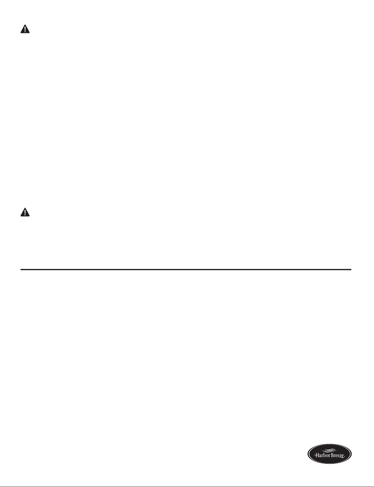
7XUQRIIHOHFWULFLW\DWPDLQIXVHER[RUFLUFXLWEUHDNHUER[EHIRUHEHJLQQLQJLQVWDOODWLRQE\UHPRYLQJIXVH
RUE\UHPRYLQJWKIXVHRUE\VZLWFKLQJRIIFLUFXLWEUHDNHU
'RQRWFRQQHFWWKLVIL[WXUHWRDQHOHFWULFDOV\VWHPWKDWGRHVQRWSURYLGHDPHDQVIRUHTXLSPHQWJURXQGLQJ
1HYHUXVHDIL[WXUHLQDWZRZLUHV\VWHPWKDWLVQRWJURXQGHG
,I\RXDUHQRWVXUH\RXUOLJKWLQJV\VWHPKDVDJURXQGLQJPHDQVGRQRWDWWHPSWWRLQVWDOOWKLVIL[WXUH&RQWDFW
DTXDOLILHGOLFHQVHGHOHFWULFLDQIRULQIRUPDWLRQUHJDUGLQJSURSHUJURXQGLQJPHWKRGVDVUHTXLUHGE\WKHORFDO
HOHFWULFDOFRGHLQ\RXUDUHD
0DNHVXUHWKHLQVWDOODWLRQVLWH\RXFKRRVHDOORZVDPLQLPXPFOHDUDQFHRIIWIURPWKHEODGHVWRWKHIORRU
DQGDWOHDVWLQIURPWKHHQGVRIWKHEODGHVWRDQ\REVWUXFWLRQ
,IDGLPPHUFRQWUROVZLWFKLVXVHGZLWKWKLVIL[WXUHREWDLQSURIHVVLRQDODGYLFHWRGHWHUPLQHWKHFRUUHFWW\SH
DQGHOHFWULFDOUDWLQJUHTXLUHG
7KHOLJKWLQJIL[WXUHPXVWEHSRVLWLRQHGVRWKHUHLVDWOHDVWIWEHWZHHQWKHEXOEDQGDQ\LOOXPLQDWHG
surface.
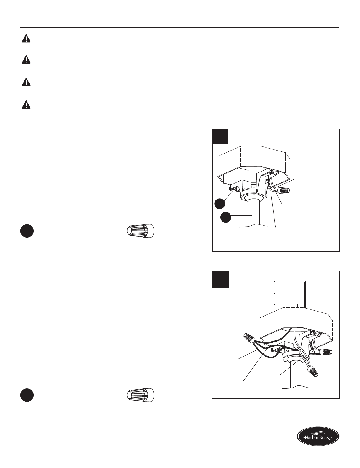
)RUVXSSO\FRQQHFWLRQVLIWKHFRQGXFWRURIDIDQLVLGHQWLILHGDVDJURXQGHGFRQGXFWRUWKHQLWVKRXOGEH
FRQQHFWHGWRDJURXQGHGFRQGXFWRUSRZHUVXSSO\,IWKHFRQGXFWRURIDIDQLVLGHQWLILHGDVDQXQJURXQGHG
FRQGXFWRUWKHQLWVKRXOGEHFRQQHFWHGWRDQXQJURXQGHGFRQGXFWRUSRZHUVXSSO\,IWKHFRQGXFWRURIDIDQ
LVLGHQWLILHGIRUHTXLSPHQWJURXQGLQJWKHQLWVKRXOGEHFRQQHFWHGWRDQHTXLSPHQWJURXQGLQJFRQGXFWRU
,QVWDOOLQJDIL[WXUHLQWRDQHOHFWULFDOV\VWHPZLWKRXWDSURSHUJURXQGLQJPHDQVFRXOGDOORZPHWDOSDUWVRIWKH
IL[WXUHWRFDUU\HOHFWULFDOFXUUHQWV,IDQ\RIWKHIL[WXUHZLUHVZLUHFRQQHFWLRQVRUVSOLFHVDUHEURNHQFXWRU
ORRVHGXULQJWKHPRXQWLQJRUQRUPDORSHUDWLRQRIWKHIL[WXUHXQGHUVXFKFRQGLWRQDQ\RQHFRPLQJLQFRQWDFW
ZLWKWKHIL[WXUHLVVXEMHFWWRHOHFWULFDOVKRFNZKLFKFRXOGFDXVHVHULRXVLQMXU\RUGHDWK
&RQQHFWLRQRIWKHEDUHRUJUHHQIL[WXUHJURXQGZLUHWRWKHEODFNRUZKLWHKRXVHZLUHVPD\DOORZPHWDOSDUWV
RIWKHIL[WXUHWRFDUU\HOHFWULFDOFXUUHQWV8QGHUWKLVFRQGLWLRQDQ\RQHFRPLQJLQFRQWDFWZLWKWKHIL[WXUHZLOO
UHFHLYHHOHFWULFDOVKRFNZKLFKFRXOGFDXVHVHULRXVLQMXU\RUGHDWK
%HFDUHIXOQRWWRGDPDJHRUFXWWKHZLUHLQVXODWLRQFRYHULQJGXULQJIL[WXUHLQVWDOODWLRQ'RQRWSHUPLWZLUHV
WRKDYHFRQWDFWZLWKDQ\VXUIDFHKDYLQJDVKDUSHGJH'RLQJVRPD\GDPDJHRUFXWWKHZLUHLQVXODWLRQ
ZKLFKFRXOGFDXVHVHULRXVLQMXU\RUGHDWKIURPHOHFWULFVKRFN
DANGER
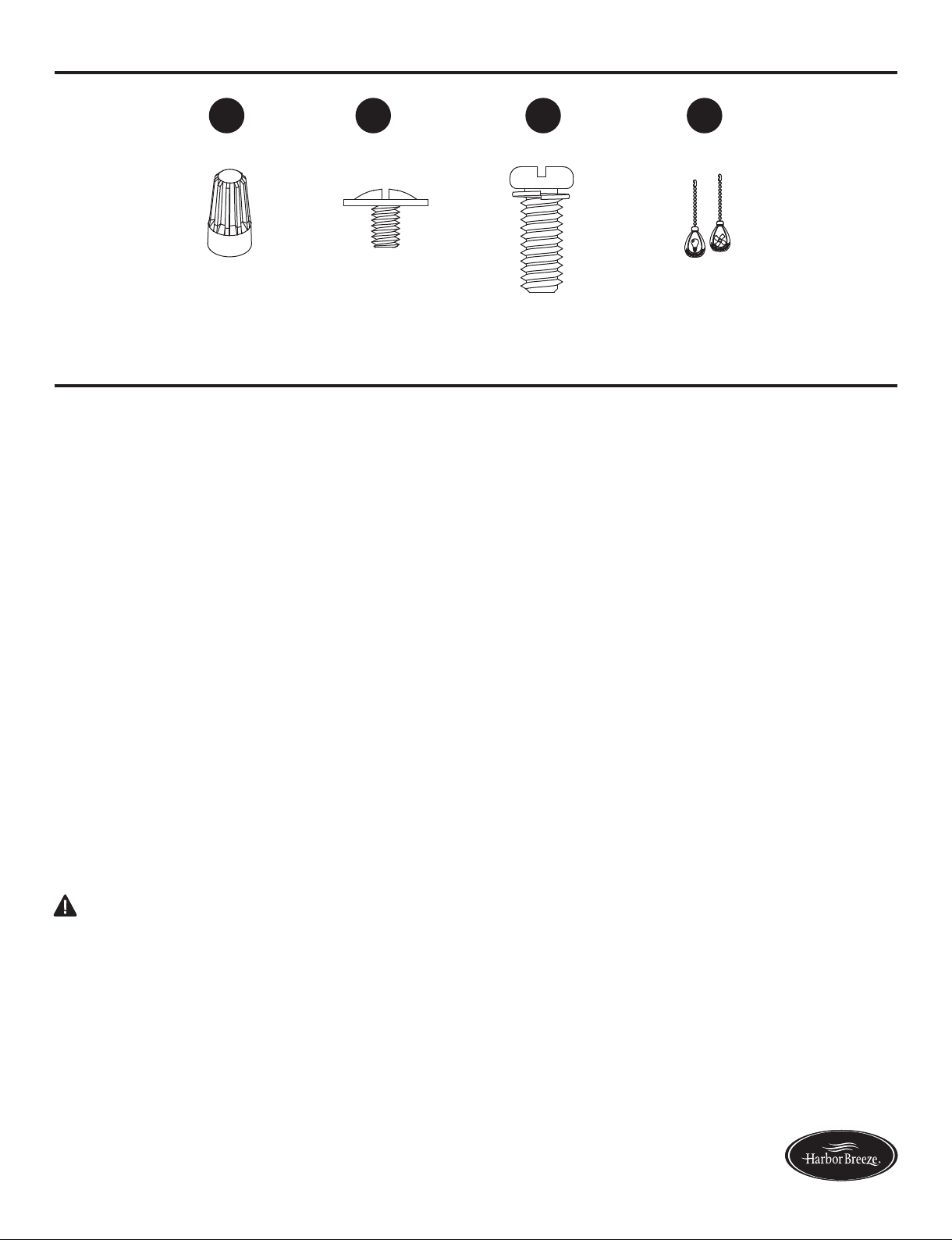
HARDWARE CONTENTS QRWVKRZQDFWXDOVL]H
/RZHVFRPKDUERUEUHH]H
AA BB CC DD
SAFETY INFORMATION
Wire &onnector
Qt\.
%lade ScreZ
Qt\. 5 + e[tra
([tra 0otor ScreZ
Qt\. 2
)ob
Qt\. 2

WARNING
CAUTION
PREPARATION
Risk of fire. Most dwellings built before 1985 have supply wire rated for 140°F. Consult a qualified
electrician before installation.
To reduce the risk of fire or electric shock, do not use this fan with any solid state fan speed device
or variable speed control.
To reduce the risk of personal injury, do not bend the blade brackets when installing the brackets,
balancing or cleaning the fan.
Do not insert foreign objects in between rotating fan blades.
Do not install or use the fan if any part is damaged or missing.
Before servicing or cleaning the unit, switch power off at the service panel and lock the service
disconnecting means to prevent power from being switched on accidentally. When the service
disconnecting means cannot be locked, securely fasten a prominent warning device, such as a tag,
to the service panel.
Do not use bulbs having a wattage greater than the maximum value stated on the fixture and in this
manual. Using a higher wattage bulb than specified will increase fixture temperature and increase
risk of fire.
Before beginning assembly of product, make sure all parts are present. Compare parts with package
contents list and hardware contents list. If any part is missing or damaged, do not attempt to assemble
the product.
To reduce the risk of fire, electric shock or personal injury, mount to metal outlet box marked
'ACCEPTABLE FOR FAN SUPPORT OF 35 LBS OR LESS' and use mounting screws provided
with the outlet box and/or support directly from building structure. Most outlet boxes commonly
used for the support of luminaries are not acceptable for fan support and may need to be replaced.
Consult a qualified electrician if in doubt.
Estimated Assembly Time: 45 minutes
Tools Required for Assembly (not included): Philips Screwdriver, Step Ladder, Tape, Pliers and Wire
Cutters.
5
Lowes.com/harborbreeze

6
Lowes.com/harborbreeze
DANGER: Failure to disconnect power supply prior
to installation may result in serious injury or death.
INITIAL INSTRUCTIONS
1. Turn off circuit breakers and wall switch to the fan
supply line leads.
1
OFF
OFF
ON
2a. Choose the desired mounting method:
2b. Make sure the installation site you choose allows a
minimum clearance of 7 ft. from the blades to the
floor and at least 30 in. from the ends of the blades
to any obstruction.
A. Standard Mounting: Standard mounting is best
suited for ceilings 8 ft. or higher. For taller ceilings you
may want to use a longer downrod (not included).
B. Angle Mounting: Angle-style mounting is best
suited for angled or vaulted ceilings. A longer downrod
is sometimes necessary to ensure proper blade
clearance. If using the angle mount, make sure the
ceiling angle is not steeper than 20°.
C. Flush Mounting: Flushmount installation is used
for ceiling less than 8 ft. high.
2a
AB
C
2b
7 ft. MIN.
30 in.
MIN.

3. Check existing outlet box (not included) to ensure it is
securely fastened to at least two points in a structural
ceiling member and can support the full weight of the
fan. Once verified, install mounting bracket (A) to the
outlet box using the screws and washers provided
with the outlet box.
4. Remove the hairpin clip (O) and clevis pin (N) from
the coupling (F) preassembled on motor housing (G).
Retain for later use.
Loosen the two coupling screws (P) preassembled in
coupling (F), but do not remove them.
1. Place downrod assembly (D) through canopy (B),
canopy cover (C) and coupling cover (E).
Note: If using the angle mount, make sure open end of
mounting bracket (A) is installed facing the higher point
of the ceiling.
3
Open End
A
A
DANGER: A loose outlet box can cause the fan to
wobble and increase the fan's potential to fall, which
could result in serious injury or death.
7
Lowes.com/harborbreeze
INITIAL INSTRUCTIONS
STANDARD/ANGLE-MOUNTING INSTRUCTIONS
C
B
D
E
1
O
P
G
F
N
N
P
4
O
F
Note: Make sure to keep loose hardware separate to
avoid confusion during installation.
For STANDARD/ANGLE-MOUNTING INSTRUCTIONS,
proceed to Step 1 below. For FLUSHMOUNT
INSTRUCTIONS, skip to page 9.

Hanger
Ball
Tab
Slot
4
D
A
DANGER: Be careful when aligning the tab to the
slot! If not fully engaged, there is a possibility of the fan
falling, which may result in serious injury or death.
CAUTION: Ensure all screws are tight before moving
onto the next step.
8
Lowes.com/harborbreeze
STANDARD/ANGLE-MOUNTING INSTRUCTIONS
2. Feed power wires from motor housing (G) through
downrod assembly (D), then insert downrod assembly
(D) into the coupling (F) on motor housing (G).
3. Cut off excess fixture wires, leaving approximately 6 to
9 inches above the top of the downrod assembly (D).
Strip 1/2 inch of insulation from the end of each fixture
wire.
4. Carefully lift assembly and rest the hanger ball of
downrod assembly (D) on the mounting bracket (A)
attached to the outlet box. Be sure the slot in the
hanger ball is lined up with the tab on the mounting
bracket (A). This will leave hands free for the wiring
process.
Proceed to WIRING INSTRUCTIONS on page 10.
Align the hole on downrod assembly (D) to hole on
coupling (F), then re-install clevis pin (N). Re-attach
hairpin clip (O) into clevis pin (N) until it snaps into
place, then tighten the two previously loosened
coupling screws (P).
F
P
O
N
G
D
2
3
6 to 9 in.
D

1
B
C
1. Press out on the inner edges of the canopy cover (C)
from inside the canopy (B) until it releases from the
canopy (B).
2. Remove the three preassembled Phillips-head screws
near the coupling (F) on the motor housing (G). Guide
power wires from motor housing (G) through the base
of the canopy (B), then attach canopy (B) to motor
housing (G) with previously removed screws. Tighten
securely.
3. Raise assembly and temporarily place one side of
canopy (B) onto hook of mounting bracket (A). This
will leave hands free for the wiring process.
Proceed to WIRING INSTRUCTIONS on next page.
9
Lowes.com/harborbreeze
FLUSHMOUNT INSTRUCTIONS
B
F
G
2Screw
3A
B
Hook
Note: Flushmount installation will not use canopy cover
(C), downrod assembly (D), coupling cover (E), clevis
pin (N), hairpin clip (O) or coupling screws (P).

1. Connect the GREEN wires from the hanger ball of
downrod assembly (D) and mounting bracket (A) to
the supply ground (GREEN or bare) wire. Securely
connect wires using wire connector (AA).
2. Securely connect the fan WHITE wire to the supply
WHITE wire using wire connector (AA). Securely
connect the fan BLACK and BLUE wires to the supply
BLACK wire using wire connector (AA).
Note: Flushmount installation will not use the Green
wire from the downrod assembly (D).
Hardware Used
Wire Connector x 1
AA
Hardware Used
Wire Connector x 2
AA
1
Supply
Ground Wire
Green Wire from
Mounting Bracket
Green Wire from
Hanger Ball
A
D
2
Black
Fan Wire
Blue
Fan Wire
BLACK
GREEN
WHITE
White
Fan Wire
WARNING: To avoid possible electrical shock, be sure electricity is turned off at the main fuse
box before hanging.
WARNING: If you are not sure if the outlet box is grounded, contact a licensed electrician for
advice, as it must be grounded for safe operation.
WARNING: If house wires are of different colors than referred to in the following steps, stop
immediately. A professional electrician is recommended to determine proper wiring.
WARNING: If you feel that you do not have enough electrical wiring knowledge or experience,
have the fan installed by a licensed electrician.
10
Lowes.com/harborbreeze
WIRING INSTRUCTIONS
Note: This is only one way to wire the fan; consult a
qualified electrician if it is not applicable to your home.
Note: The BLACK wire is hot power for the fan. The
WHITE wire is common for the fan and light. The BLUE
wire is hot power for the light. The GREEN wire is the
ground wire.

3. Wrap electrical tape (not included) around each wire
connector (AA) and make sure no bare wire or wire
strands are visible after making connections.
Then, turn wires upward and carefully push them into
the outlet box; make sure the WHITE and GREEN
connections are on one side and the BLACK
connections are on the other side.
3
BLACK
BLUE
WHITE
GREEN
Outlet Box
A
B
R
B
C
1
11
WIRING INSTRUCTIONS
FINAL INSTRUCTIONS
1. Loosen (but do not remove) the two preassembled
mounting bracket screws (R) on mounting bracket (A)
that align with the slotted holes on canopy (B). Remove
the other two mounting bracket screws (R).
2. Position one blade iron (I) under blade (J). Insert
three blade screws (BB) through blade (J) and into
blade iron (I). Tighten each blade screw (BB) evenly,
starting with the center blade screw (BB). Repeat for
the remaining blade assemblies.
Lift canopy (B) up so slotted holes engage loosened
screw heads on mounting bracket (A), then twist
canopy (B) clockwise. Re-install previously removed
mounting bracket screws (R), then tighten all screws
securely.
Hardware Used
Blade Screw x 15
BB
Lowes.com/harborbreeze
2
J
BB
I
Note: Flushmount installation will not use the downrod assembly (D), canopy cover (C) or coupling
cover (E) as shown.
Note: If the canopy cover (C) is loosened during
installation, press it to the inner edge of the canopy (B).

12
FINAL INSTRUCTIONS
4. Remove three switch housing screws (S) preinstalled on
the switch housing (H) and save them for later use.
5. Attach the connector from the light kit (K) to the
connector from the motor housing (G).
Then, align the light kit (K) to the switch housing (H)
and secure with the switch housing screws (S)
previously removed.
5
Lowes.com/harborbreeze
H
K
S
G
4
S
H
3. Loosen (do not remove) the motor screws (T) from
motor housing (G) and discard the preassembled
motor blocks. Slide the blade assemblies onto motor
housing (G) and tighten the motor screws (T) securely.
3
G
T
Motor Block
Note: If you misplace one or two motor screws during
installation of the blade assemblies, use the extra motor
screws (CC) instead.
Note: The two connectors have keyholes that must be
mated correctly before they can be engaged.
Note: Make sure to keep loose hardware separate to
avoid confusion during installation.

13
8. Install bulbs (M) into each socket.
CAUTION: If you replace the bulbs (M) with more
than 190 watts, the fixture will automatically turn off.
When replacing bulbs, ensure bulb wattage is below
190 watts.
Lowes.com/harborbreeze
7. Slide glass bowl (L) to each socket, securing with socket
rings (U).
FINAL INSTRUCTIONS
8
M
7
L
L
V
U
6. Remove socket ring (U) from each socket on light kit (K). 6
U
K

14
Lowes.com/harborbreeze
1
FINAL INSTRUCTIONS
OPERATING INSTRUCTIONS
DD
2
2. When the season changes, you may want to change
the direction the fan spins. In warmer weather,
counterclockwise rotation creates a downward air flow,
which cools the air. Push the reverse switch located on
light kit (K) LEFT and see a SUN icon. In cooler
weather, clockwise rotation creates an upward air flow,
which moves hot air from the ceiling into room. Push
the reverse switch RIGHT and see a SNOWFLAKE icon.
9. Connect the fobs (DD) to the appropriate pull chains.
1. The fob (DD) marked with a fan image is for motor
speed control: High, Medium, Low and Off. Pull once
for each position.
The fob (DD) marked with a lamp image controls the
light, either ON or OFF with each pull of the chain.
9
Hardware Used
DD Fob x 2
DD
Note: Use a small screwdriver or ballpoint pen to move
the reverse switch if you have difficulty doing so by hand.
Note: Make sure reverse switch is firmly in left or right
position. Fan will not operate when switch is in the middle.
CAUTION: Turn off and wait for fan to stop before
moving the reverse switch.

15
Lowes.com/harborbreeze
TROUBLESHOOTING
CARE AND MAINTENANCE
Important: Shut off main power supply before beginning any maintenance. Do not use water or
a damp cloth to clean the ceiling fan.
At least twice each year, tighten all screws and lower canopy to check mounting plate screws.
Bulb Replacement: Use three 40-watt max. type-A15 incandescent bulbs. CFL bulbs are not
recommended for this item.
Clean fan housing with only a soft brush or lint-free cloth to avoid scratching the finish. Clean
blades with a lint-free cloth. You may occasionally apply a light coat of furniture polish to wood
blades for added protection.
1. Set screws are loose. 1. Tighten all set screws.
2. Using non-approved speed
control.
2. Some fan motors are sensitive to signals
from solid-state varible speed controls. DO
NOT USE a solid-state variable speed control.
3. Normal noise. 3. Allow "break-in" period of 24 hours. Most
noises associated with a new fan will disappear
after this period.
4. Wire connectors inside
switch housing rattling.
4. Check to make sure wire connectors in
switch housing are not rattling against each
other or against the interior wall of the switch
housing.
5. Cracked blade. 5. Replace blades.
6. The distance from canopy
to ceiling is too great.
6. Make sure upper canopy is a short distance
from ceiling. It should not touch the ceiling.
7. Faulty light bulb installation. 7. Make sure light bulb is tight in socket and
does not touch glass shade.
8. Glass is not secure. 8. Secure the glass.
1. Hanger bracket and/or
ceiling outlet box is not
securely fastened.
1. Tighten the hanger bracket screws to the
outlet box, and/or secure outlet box.
2. Set screw in downrod
assembly is loose.
2. Tighten the set screw in the downrod
assembly.
3. Fan hanger ball is not
properly seated in canopy tabs.
3. Turn power off, support the fan very
carefully, and check that the hanger ball is
properly seated.
4. Set screw in motor coupling
is loose.
4. Raise motor coupling up and tighten set
screws securely.
5. Blade is loose. 5. Check that all blades are screwed firmly into
blade holders.
Fan wobbles.
Fan sounds noisy.
PROBLEM PROBABLE CAUSE CORRECTIVE ACTION

TROUBLESHOOTING
16
Lowes.com/harborbreeze
Fan Wobbles.
8. Fan too close to vaulted
ceiling.
8. Lower or move fan. Extension downrods
may be ordered.
9. Transition to different speed.
9. When switching from medium to low speed,
you may notice some fan wobble in the fan.
When the fan stabilizes at low speed, wobble
should disappear.
10. Fan not securely mounted. 10. Make sure canopy and mounting bracket
are tightened securely to ceiling joist.
1. Power turned off, fuse blown
or circuit breaker tripped.
1. Turn power on, replace fuse or reset breaker.
3. Motor reversing switch not
engaged.
3. Push switch firmly right or left. Fan will not
operate when switch is in the middle.
4. Pull chain switch not "on". 4. Pull switch chain.
1. Wrong wire connection. 1. Refer to Step 1, page 10 to ensure all wire
connections were done correctly.
2. Bulb is burned out. 2. Replace the bulbs.
Light does not work.
Fan does not start
2b. Check the plug connection in the switch
housing.
2a. Turn power off and loosen canopy; check
all connections according to section WIRING
INSTRUCTIONS on page 10.
2. Loose wire connections or
wrong connections.
PROBLEM PROBABLE CAUSE CORRECTIVE ACTION
.
6. Blade holders are loose. 6. Check to be sure the fan blade irons seat
firmly and uniformly on the surface of the motor.
If flanges are
seated incorrectly, loosen the
flange screws and retighten.
7. Blade out of balance. 7. Interchange two adjacent blades; this will
redistribute the weight and possibly result in
smoother operation. Or, refer to the instructions
inside the balance kit (Q).

17
Lowes.com/harborbreeze
The manufacturer warrants this fan to be free from defects in workmanship and material present at
time of shipment from the factory for life (with limitations) from the date of purchase. This warranty
applies only to the original purchaser. The manufacturer agrees to correct such defect at no charge
or, at our option, replace the ceiling fan with a comparable or superior model.
To obtain warranty service, present a copy of your sales receipt as proof of purchase. All cost of
removal and reinstallation are the expressed responsibility of the purchaser. Any damage to the
ceiling fan by accident, misuse or improper installation, or by affixing accessories not produced by
this warranty, are at the purchaser’s own responsibility. The manufacturer assumes no responsibility
whatsoever for fan installation during the limited lifetime warranty. Any service performed by an
unauthorized person will render the warranty invalid.
Due to varying climatic conditions, this warranty does not cover changes in brass finish, rusting,
pitting, tarnishing, corroding or peeling. Brass finish fans maintain their beauty when protected from
varying weather conditions.
The duration of any implied warranty which can not be disclaimed is limited to the lifetime limited period
as specified in our warranty. The manufacturer shall not be liable for incidental, consequential or special
damages arising at or in connection with product use or performance except as may other wise be
accorded by law. This warranty gives you specific legal rights, and you also have other rights which vary
from state to state. This warranty supersedes all prior warranties.
NOTE: A small amount of “ wobble ” is normal and should not be considered a defect.
Any replacement of defective parts for the ceiling fan must be reported within the first year from the
date of purchase. For the balance of the warranty, call our customer service department at 1-800-643-
0067 for return authorization and shipping instructions so that we may repair or replace the ceiling fan.
Any fan or parts returned improperly packaged is the sole responsibility of the purchaser. There is no
further expressed warranty. The manufacturer disclaims any and all implied warranties.
LIMITED LIFETIME WARRANTY

18
Lowes.com/harborbreeze
REPLACEMENT PARTS LIST
For replacement parts, call our customer service department at 1-800-643-0067, 8 a.m. - 6 p.m., EST,
Monday - Thursday, 8 a.m. - 5 p.m., EST, Friday.
Printed in China
AA BB
Harbor Breeze®is a registered trademark of LF, LLC. All Rights Reserved.
E
D
C
B
A
IJ
L
V
U
K
CC DD
A Mounting Bracket A102-0132031
B Canopy A101-0347084
C Canopy Cover A108-0230084
D Downrod Assembly A103-0156084
E Coupling Cover A106-1262084
I Blade Iron A143-0253084
J Blade A141-0370036
K Light Kit A187-0288084
L Glass Bowl
U Socket Ring
V Locking Ring Tool
A182-0287036
B172-0036045
B171-0273005
AA Wire Connector
BB Blade Screw
CC Extra Motor Screw
DD Fob
B168-0387018
Part Description Part#
Table of contents
Other Harbor Breeze Ceiling Fan manuals