Harbor Freight Tools One Stop Gardens 93455 User manual

ANGEL WATER FOUNTAIN
Model 93455
ASSEMBLY AND OPERATING INSTRUCTIONS
3491 Mission Oaks Blvd., Camarillo, CA 93011
Visit our Web site at: http://www.harborfreight.com
Copyright 2005 by Harbor Freight Tools®. All rights reserved. No portion of this
manual or any artwork contained herein may be reproduced in any shape or form
without the express written consent of Harbor Freight Tools.
For technical questions, please call 1-800-444-3353.
®
©
TO PREVENT SERIOUS INJURY,
READ AND UNDERSTAND ALL WARNINGS
AND INSTRUCTIONS BEFORE USE.
Due to continuing improvements, actual product may differ slightly from the product described herein.

SKU 93455 For technical questions, please call 1-800-444-3353. Page 2
PRODUCT SPECIFICATIONS
SAVE THIS MANUAL
You will need this manual for the safety warnings and precautions, assembly, operating,
inspection, maintenance and cleaning procedures, parts list and assembly diagram. Keep
your invoice with this manual. Write the invoice number on the inside of the front cover.
Keep this manual and invoice in a safe and dry place for future reference.
GENERAL SAFETY RULES
WARNING!
READ AND UNDERSTAND ALL INSTRUCTIONS
Failure to follow all instructions listed below may result in
electric shock, fire, and/or serious injury.
SAVE THESE INSTRUCTIONS
WORK AREA
1. Keep your work area clean and well lit. Cluttered benches and dark areas
invite accidents.
2. Do not operate power tools in explosive atmospheres, such as in the
presence of flammable liquids, gases, or dust. Power tools create sparks
which may ignite the dust or fumes.
3. Keep bystanders, children, and visitors away while operating a power tool.
Distractions can cause you to lose control. Protect others in the work area from
debris such as chips and sparks. Provide barriers or shields as needed.
ELECTRICAL SAFETY
4. Grounded tools must be plugged into an outlet properly installed and
Item Description
Electrical Requirements Input: 120 VAC / 60 Hz / 2 Watts
Output: 12 VAC / 200 mA
Power Cord: 6’-5”
Power Plug: 2-Prong
Water Pump Self-Priming / ¼” Outlet Nipple
Bowl Dimensions 9-1/2” Diameter x 3-3/4” High
Bowl Base Dimensions 5-7/8” Diameter x 3/4” High
Statue Dimensions 13-1/8” High x 5-1/8” Rear to Rear x 4-7/8” Side to Side
Overall Dimensions 13-1/2” High x 9-1/2” Diameter
Unit Weight 6.50 Pounds

SKU 93455 For technical questions, please call 1-800-444-3353. Page 3
grounded in accordance with all codes and ordinances. Never remove the
grounding prong or modify the plug in any way. Do not use any adapter
plugs. Check with a qualified electrician if you are in doubt as to whether
the outlet is properly grounded. If the tools should electrically malfunction or
break down, grounding provides a low resistance path to carry electricity away
from the user.
5. Double insulated tools are equipped with a polarized plug (one blade is
wider than the other). This plug will fit in a polarized outlet only one way. If
the plug does not fit fully in the outlet, reverse the plug. If it still does not
fit, contact a qualified electrician to install a polarized outlet. Do not
change the plug in any way. Double insulation eliminates the need for the
three wire grounded power cord and grounded power supply system.
6. Avoid body contact with grounded surfaces such as pipes, radiators,
ranges, and refrigerators. There is an increased risk of electric shock if your
body is grounded.
7. Do not abuse the Power Cord. Never use the Power Cord to carry the tools
or pull the Plug from an outlet. Keep the Power Cord away from heat, oil,
sharp edges, or moving parts. Replace damaged Power Cords immediately.
Damaged Power Cords increase the risk of electric shock.
8. When operating a power tool outside, use an outdoor extension cord
marked “W-A” or “W”. These extension cords are rated for outdoor use, and
reduce the risk of electric shock.
PERSONAL SAFETY
9. Stay alert. Watch what you are doing, and use common sense when
operating this product. Do not use the Fountain while tired or under the
influence of drugs, alcohol, or medication. A moment of inattention while
operating this product may result in serious personal injury.
10. Dress properly. Do not wear loose clothing or jewelry. Contain long hair.
Keep your hair, clothing, and gloves away from moving parts. Loose
clothes, jewelry, or long hair can be caught in moving parts.
11. Avoid accidental starting. Make sure the Power Cord remains unplugged from
its electrical outlet until this product is completely assembled, filled with water,
and ready to use.
12. Do not overreach. Keep proper footing and balance at all times. Proper
footing and balance enables better control of this product in unexpected
situations.

SKU 93455 For technical questions, please call 1-800-444-3353. Page 4
13. Use safety equipment. Wear eye protection when assembling this product.
Non-skid safety shoes must be used for appropriate conditions.
TOOL USE AND CARE
14. Disconnect the Power Cord Plug from the power source before making any
adjustments, changing accessories, or storing the Fountain. Such preventive
safety measures reduce the risk of starting the unit accidentally.
15. Store idle equipment out of reach of children and other untrained persons.
Electrically powered products are dangerous in the hands of untrained users.
16. Check for misalignment or binding of moving parts, breakage of parts, and
any other condition that may affect this product’s operation. If damaged,
have the Fountain serviced before using. Many accidents are caused by
poorly maintained equipment.
SERVICE
17. Service must be performed only by qualified repair personnel. Service
or maintenance performed by unqualified personnel could result in a risk of injury.
18. When servicing this product, use only identical replacement parts. Follow
instructions in the
“Inspection, Maintenance, And Cleaning”
section of this
manual. Use of unauthorized parts or failure to follow maintenance instructions
may create a risk of electric shock or injury.
SPECIFIC SAFETY RULES
1. Maintain labels and nameplates on the Fountain. These carry important
information. If unreadable or missing, contact Harbor Freight Tools for a replace-
ment.
2. Wear ANSI approved safety impact eye goggles and heavy duty work
gloves when assembling the Fountain. Using personal safety devices reduce
the risk for injury. Safety impact eye goggles and heavy duty work gloves are
available from Harbor Freight Tools.

SKU 93455 For technical questions, please call 1-800-444-3353. Page 5
3. Maintain a safe environment. Keep the area well lit. Make sure there is
adequate surrounding space. Always keep the area free of obstructions, grease,
oil, trash, and other debris. Do not use an electrically powered product in areas
near flammable chemicals, dusts, and vapors.
4. Carefully inspect the condition of the Fountain before use, and check the
Fountain periodically during use. If any damage is noted, stop immediately and
repair or replace the Fountain.
5. Make sure the Water Pump (4) is unplugged from its electrical outlet prior to
performing any inspection, maintenance, or cleaning procedures.
6. CAUTION! Excessive weight or pressure on any of the Fountain sections
may cause it to tip and/or fall. Keep children and pets away from any of the Foun-
tain sections and the Power Cord.
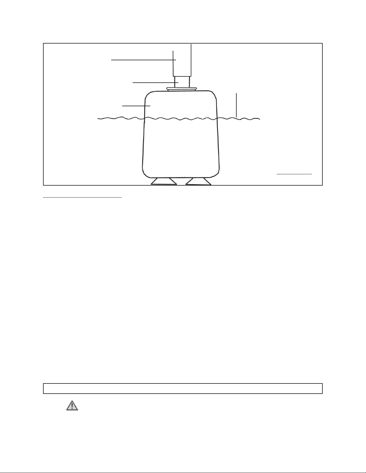
7. Use the Water Pump (4) with cold, distilled water only. Mineral buildup from
tap water, or water from other sources, can ruin the Water Pump.
8. Make sure the water supply used for the Fountain is not dirty, sandy, and
does not contain any corrosive chemical products. Change the water when
necessary and rinse out the Bowl (3).
9. Running the Water Pump (4) without sufficient water can damage the Pump.
This Pump requires a minimum of 2 inches of water at all times.
10. If locating the Fountain on a table, make sure the table is flat, level, dry, and
sturdy enough to support the weight of the Fountain and its water.
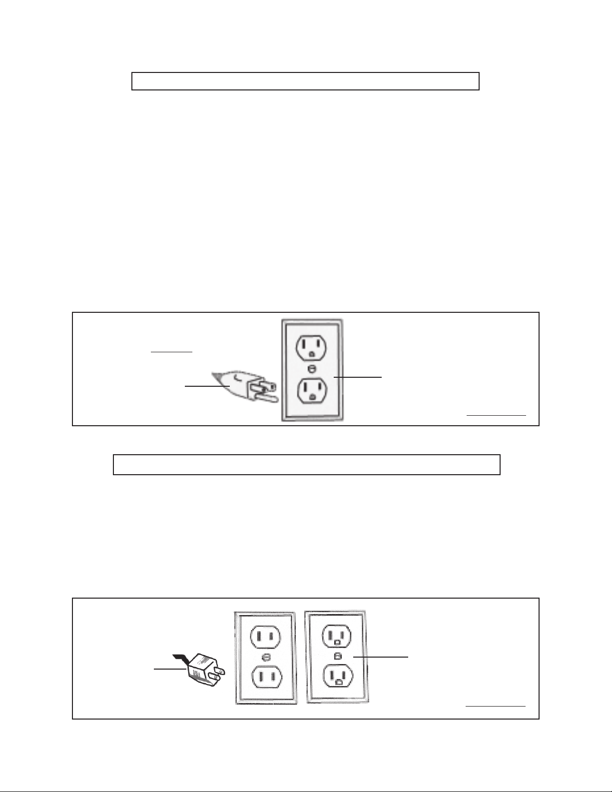
11. Avoid accidental electric shock. Keep all electrically powered products
away from the Fountain. Disconnect the Water Pump (4) from its electrical
outlet before placing hands in the Bowl (3) filled with water. Make sure to
stand on a dry, insulated surface such as a rubber mat while using the
Fountain.
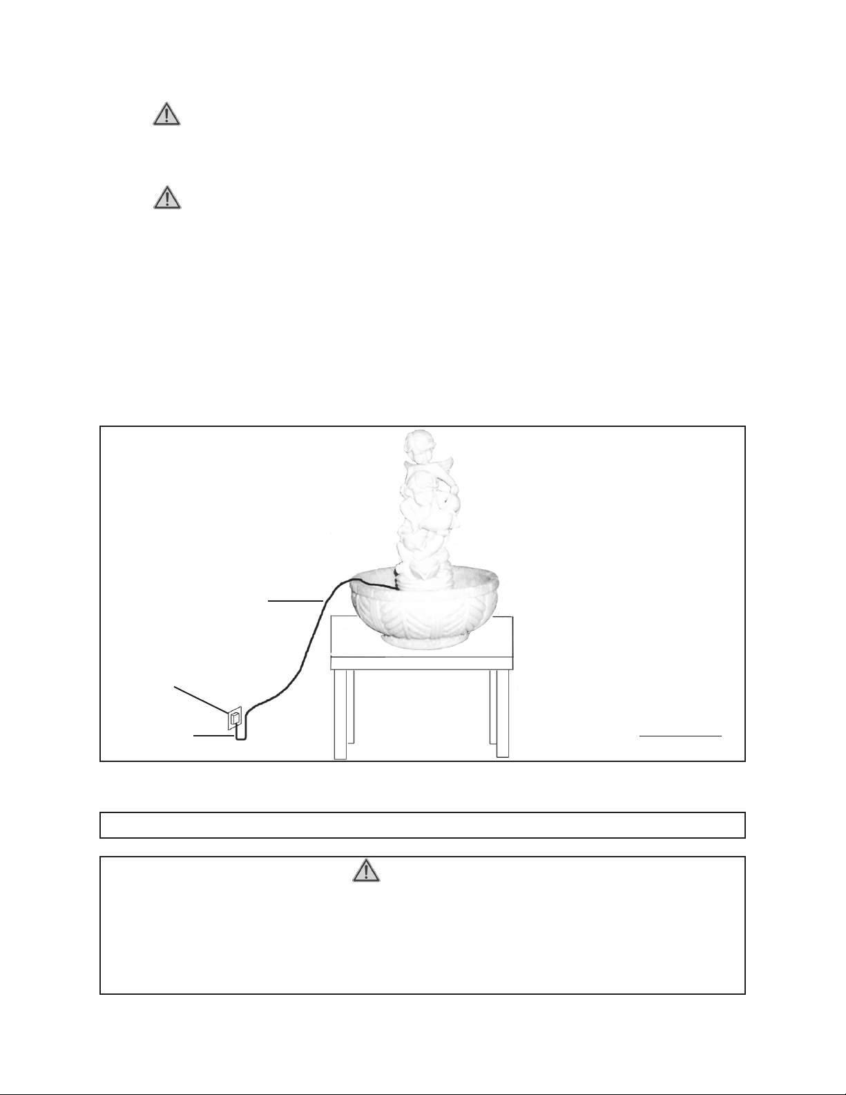
13. Always arrange a “drip loop” in the Power Cord connecting the Water Pump
(4) to a 120 volt, grounded, electrical outlet. A drip loop is that part of the Power
Cord below the level of the electrical outlet (or the connector if an extension cord
is used) to prevent water traveling along the Power Cord and coming in contact
with the outlet. If the Power Cord Plug or outlet does get wet, do not unplug the
Power Cord Plug. Disconnect the fuse or circuit breaker that supplies power to
the electrical outlet. Then, unplug the Power Cord and examine for presence of
water in the outlet. (See Figure A.)

SKU 93455 For technical questions, please call 1-800-444-3353. Page 6
14. WARNING! People with pacemakers should consult their physician(s)
before using this product. Operation of electrical equipment in close proximity to
a heart pacemaker could cause interference or failure of the pacemaker.
15. WARNING! The warnings and cautions discussed in this manual cannot
cover all possible conditions and situations that may occur. It must be understood
by the operator that common sense and caution are factors which cannot be built
into this product, but must be supplied by the operator.
SAVE THESE INSTRUCTIONS
GROUNDING
WARNING!
Improperly connecting the grounding wire can result in the risk of electric shock. Check
with a qualified electrician if you are in doubt as to whether the outlet is properly grounded.
Do not modify the power cord plug provided with the tool. Never remove the grounding
prong from the plug. Do not use the tool if the power cord or plug is damaged. If damaged,
have it repaired by a service facility before use. If the plug will not fit the outlet, have a
proper outlet installed by a qualified electrician.
120 VOLT, GROUNDED,
ELECTRICAL OUTLET
DRIP LOOP
POWER CORD
FIGURE A

SKU 93455 For technical questions, please call 1-800-444-3353. Page 7
GROUNDED TOOLS: TOOLS WITH THREE PRONG PLUGS
1. Tools marked with “Grounding Required” have a three wire cord and three prong
grounding plug. The plug must be connected to a properly grounded outlet. If
the tool should electrically malfunction or break down, grounding provides a low
resistance path to carry electricity away from the user, reducing the risk of electric
shock. (See Figure B.)
2. The grounding prong in the plug is connected through the green wire inside the
cord to the grounding system in the tool. The green wire in the cord must be the
only wire connected to the tool’s grounding system and must never be attached
to an electrically “live” terminal. (See Figure B.)
3. Your tool must be plugged into an appropriate outlet, properly installed and
grounded in accordance with all codes and ordinances. The plug and outlet
should look like those in the following illustration. (See Figure B.)
THIS PRODUCT
DOES NOT
USE A
3-PRONG
ELECTRICAL
PLUG
120 VOLT,
GROUNDED,
ELECTRICAL OUTLET
FIGURE B
DOUBLE INSULATED TOOLS: TOOLS WITH TWO PRONG PLUGS
4. Tools marked “Double Insulated” do not require grounding. They have a special
double insulation system which satisfies OSHA requirements and complies with
the applicable standards of Underwriters Laboratories, Inc., the Canadian
Standard Association, and the National Electrical Code. (See Figure C.)
5. Double insulated tools may be used in either of the 120 volt outlets shown in the
following illustration. (See Figure C.)
THIS PRODUCT
USES A
2-PRONG
ELECTRICAL
PLUG
120 VOLT,
GROUNDED,
ELECTRICAL OUTLETS
FIGURE C

SKU 93455 For technical questions, please call 1-800-444-3353. Page 8
EXTENSION CORDS
1.
Grounded
tools require a three wire extension cord.
Double Insulated
tools
can use either a two or three wire extension cord.
2. As the distance from the supply outlet increases, you must use a heavier gauge
extension cord. Using extension cords with inadequately sized wire causes a
serious drop in voltage, resulting in loss of power and possible tool damage.
(See Figure D.)
3. The smaller the gauge number of the wire, the greater the capacity of the cord.
For example, a 14 gauge cord can carry a higher current than a 16 gauge cord.
(See Figure D.)
RECOMMENDED MINIMUM WIRE GAUGE FOR EXTENSION CORD
S
(120 VOLT)
NAMEPLATE
AMPERES
(At Full Load)
EXTENSION CORD LENGTH
25
Feet
50
Feet
75
Feet
100
Feet
150
Feet
0 – 2.0 18 18 18 18 16
2.1 – 3.4 18 18 18 16 14
3.5 – 5.0 18 18 16 14 12
5.1 – 7.0 18 16 14 12 12
7.1 – 12.0 18 14 12 10 -
12.1 – 16.0 14 12 10 - -
16.1 – 20.0 12 10 - - -
* Based on limiting the line voltage drop
to five volts at 150% of the rated amperes.
4. When using more than one extension cord to make up the total length, make
sure each cord contains at least the minimum wire size required.
(See Figure D.)
5. If you are using one extension cord for more than one tool, add the nameplate
amperes and use the sum to determine the required minimum cord size.
(See Figure D.)
6. If you are using an extension cord outdoors, make sure it is marked with the
suffix “W-A” (“W” in Canada) to indicate it is acceptable for outdoor use.
7. Make sure your extension cord is properly wired and in good electrical condition.
Always replace a damaged extension cord or have it repaired by a qualified
electrician before using it.
8. Protect your extension cords from sharp objects, excessive heat, and damp or
wet areas.
FIGURE D

SKU 93455 For technical questions, please call 1-800-444-3353. Page 9
SYMBOLOGY
V ~
A
xxxx/min.
no
Double Insulated
Canadian Standards
Association
Underwriters
Laboratories, Inc.
Volts Alternating Current
Amperes
No Load Revolutions
per Minute (RPM) FIGURE E
UNPACKING
When unpacking, check to make sure all the parts shown on the Parts List on page 12
are included. If any parts are missing or broken, please call Harbor Freight Tools at the
number shown on the cover of this manual as soon as possible.
ASSEMBLY AND OPERATING INSTRUCTIONS
NOTE:
For additional information regarding the parts listed in the
following pages, refer to the Assembly Diagram on page 12.
Some assembly is required, as shown below.
WARNING! Always make sure the Water Pump (4) is disconnected from its
electrical outlet prior to assembling the Fountain, adding any water, or performing
service to the product.
Assembly Instructions:
1. Set the Statue (1) into the Bowl (3), making sure to route the Hose (2) into the
Bowl. (See Assy. Diagram.)
2. Set the Water Pump (4) at the bottom of the Bowl (3). (See Assy. Diagram.)
3. Connect the Hose (2) to the Connector Tube (5) on the Water Pump (4).
(See Assy. Diagram.)
4. Fill the Bowl (3) with a minimum 2” of water. Do not overfill the Bowl.
(See Figure F, next page.)

SKU 93455 For technical questions, please call 1-800-444-3353. Page 10
WATER PUMP (4)
2” MINIMUM WATER LEVEL
FOR BEST RESULTS,
COMPLETELY SUBMERGE THE
WATER PUMP.
CONNECTOR TUBE (5)
HOSE (2)
FIGURE F
Operating Instructions:
CAUTION: Make sure your hands and feet as well as the Transformer (8), are dry, before
plugging in the Transformer.
1. Plug the Transformer (8) into the nearest 120 volt, grounded, electrical outlet,
making sure to arrange a “drip loop” in the Transformer’s Power Cord. The Water
Pump (4) will now run continuously until it is unplugged from its electrical outlet.
(See Figure A.)
2. Allow sufficient time for the Water Pump (4) to move water upward into the top of
the Statue (1). Once the Statue is filled with water, the water will begin cascading
downward into the Bowl (3) where it will again be pumped upward to repeat
the process. (See Assy. Diagram.)
3. When finished using the Fountain, always unplug the Transformer (8) from the
electrical outlet. Drain the Fountain of all water. Then store the unit in a clean,
dry, safe location out of reach of children.
INSPECTION, MAINTENANCE, AND CLEANING
1. WARNING! Make sure the Transformer (8) is disconnected from its electrical
outlet prior to performing any inspection, maintenance, or cleaning procedures.

SKU 93455 For technical questions, please call 1-800-444-3353. Page 11
2. Before each use, inspect the general condition of the Fountain. Check for
cracked or broken parts, damaged electrical wiring, and any other condition that
may affect safe operation. If abnormal noise or vibration occurs, have the problem
corrected before further use. Do not use damaged equipment.
3. To clean the Water Pump Impeller: A clogged or dirty Pump Impeller (12) will
greatly reduce performance of the Fountain. To clean the Impeller, remove the
Back Cover (13) of the Pump to expose the Impeller. Use a stream of clean
water to clean the Impeller and Impeller area inside the Pump. Then, replace the
Back Cover.
4. When storing, make sure to store the Fountain in a clean, dry, safe location out of
reach of children.
5. CAUTION! All maintenance, service, or repairs not mentioned in this
manual must only be performed by a qualified service technician.
TROUBLESHOOTING
Problem Possible Solution
The Water Pump (4) is plugged in, but
fails to operate.
Make sure the Transformer (8) of the Pump is plugged
into a working 120 volt, grounded, electrical outlet.
Check the fuse or circuit breaker supplying power to
the electrical outlet.
Make sure there is at least 2” of water in the Bowl (3).
For best results, completely submerge the Water Pump
in water.
Check the water intake area of the Water Pump for
excessive debris build-up. If necessary, clean the
intake area.
Check the Hose (2) for kinks and obstructions. If
necessary, flush out with a garden hose.
Remove the Back Cover (13) of the Water Pump to
access the Impeller (12) area. Clean the Impeller and
Impeller area. Then, turn the Impeller to ensure it is not
jammed or broken.

SKU 93455 For technical questions, please call 1-800-444-3353. Page 12
PARTS LIST AND ASSEMBLY DIAGRAM
NOTE:
Some parts are listed and shown for illustration purposes only,
and are not available individually as replacement parts.
Part # Description Qty.
1 Statue 1
2 Hose 1
3 Bowl 1
4 Water Pump 1
5 Connector Tube 1
8 Transformer 1
13 Back Cover 1
14 Suction Cup 3
1
2
3
4
4
5
8
13
14
PLEASE READ THE FOLLOWING CAREFULLY
THE MANUFACTURER AND/OR DISTRIBUTOR HAS PROVIDED THE PARTS LIST AND ASSEMBLY
DIAGRAM IN THIS MANUAL AS A REFERENCE TOOL ONLY. NEITHER THE MANUFACTURER OR
DISTRIBUTOR MAKES ANY REPRESENTATION OR WARRANTY OF ANY KIND TO THE BUYER THAT
HE OR SHE IS QUALIFIED TO REPLACE ANY PARTS OF THE PRODUCT. IN FACT, THE MANUFAC-
TURER AND/OR DISTRIBUTOR EXPRESSLY STATES THAT ALL REPAIRS AND PARTS REPLACE-
MENTS SHOULD BE UNDERTAKEN BY CERTIFIED AND LICENSED TECHNICIANS, AND NOT BY
THE BUYER. THE BUYER ASSUMES ALL RISKS AND LIABILITY ARISING OUT OF HIS OR HER
REPAIRS TO THE ORIGINAL PRODUCT OR REPLACEMENT PARTS THERETO, OR ARISING OUT OF
HIS OR HER INSTALLATION OF REPLACEMENT PARTS THERETO.
Table of contents
Other Harbor Freight Tools Outdoor Fountain manuals
Popular Outdoor Fountain manuals by other brands

Murdock
Murdock A152-VR-BF4 Series Installation & maintenance instructions

Kasco marine
Kasco marine 1400JFL owner's manual

CLIMAQUA
CLIMAQUA YOKO instructions

Campania International
Campania International Artifact M Series Assembly instructions

Campania International
Campania International FT-52 quick start guide

BENITO
BENITO TREVI Assembly instructions

One Stop Gardens
One Stop Gardens 4831 Assembly and operating instructions

Alpine
Alpine MLT102 manual

Urban
Urban A300D Installation, operation and maintenance instructions

Alpine
Alpine GIL1482 owner's manual

Campania International
Campania International Longmeadow Assembly instructions

Alpine
Alpine WIN582 owner's manual