HARD Stockton N1035P Assembly instructions

Revised 2020.1 6.12.2020
MODELS N1035P & N2085P
HOME CARE MANUAL
STOCKTON BED
CAREGIVER INFORMATION &
ASSEMBLY INSTRUCTIONS
The nations #1 manufacturer of hospital cribs

Never leave the person in the bed unattended when the side rail is lowered, or when
the head is elevated if there is any risk they will be able to get over the side rails and fall.
The mattress and/or heavy duty bumper pads should be checked regularly and replaced
if there are any tears in the fabric.
Never replace the mattress that Hard Manufacturing provides with another manufacturer's
product. Our mattresses are a custom size and other mattresses not supplied by
Hard Manufacturing may not fit properly and could potentially cause entrapment hazards.
An improper mattress will also make the bed difficult to operate as they will most likely be too
wide, and may cause damage to the bed components over time.
The weight limit of any of the cribs or beds made by Hard Manufacturing is 150lbs. If the
weight limit of the bed is exceeded, the additional weight could cause damage to the bed
components that could lead to expensive repairs and/or make the bed unsafe for daily use
for the patient as a result. A parent/caregiver should not get into the bed with the patient.
HARD Manufacturing will support parts on our cribs and beds for up to 12 years from
the date of manufacture as long as we still make the part or can obtain it from our vendors.
HARD Manufacturing cribs and beds can be cleaned with an anti-bacterial all purpose
cleaner of the parent/caregiver choice but it must be a non-abrasive cleaner. Anything
containing bleach, alcohol or ammonia must be avoided. The crib should be dried
thoroughly with a soft cloth immediately following the cleaning, the crib should never be
allowed to air dry. Failure to follow the proper cleaning instructions can result in
premature rust and corrosion of the parts on your cribs.
If the crib or bed for your child needs a part, new mattress, bumper
pads, etc- please contact the durable medical equipment dealer who
purchased the bed on behalf of your child or the patient.
Please write the info here for your reference if needed at a later date:
Dealer name:______________________________________________________________
Dealer phone number_______________________________________________________
Model # of the crib or bed purchased___________________________________________
Date the crib or bed was manufactured__________________________________________
The sticker with the model # and date of manufacture is on the crib or bed and will look like
the following example:
GENERAL INFORMATION FOR CAREGIVERS
SIDE RAIL OPERATION & SAFETY
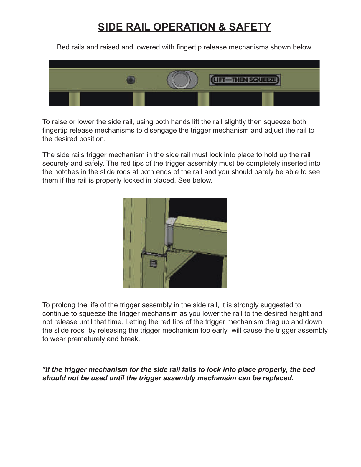
To raise or lower the side rail, using both hands lift the rail slightly then squeeze both
fingertip release mechanisms to disengage the trigger mechanism and adjust the rail to
the desired position.
Bed rails and raised and lowered with fingertip release mechanisms shown below.
To prolong the life of the trigger assembly in the side rail, it is strongly suggested to
continue to squeeze the trigger mechansim as you lower the rail to the desired height and
not release until that time. Letting the red tips of the trigger mechanism drag up and down
the slide rods by releasing the trigger mechanism too early will cause the trigger assembly
to wear prematurely and break.
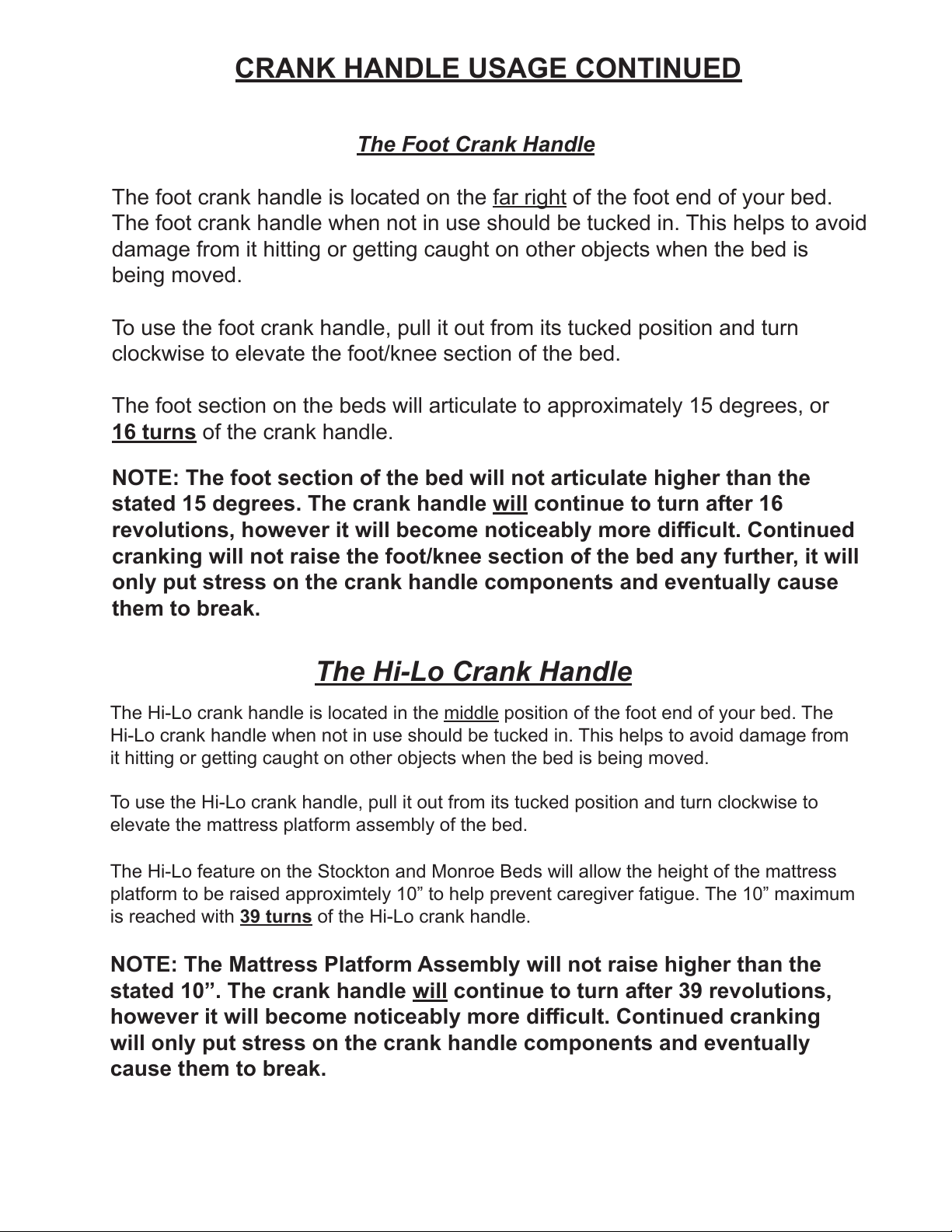
The side rails trigger mechanism in the side rail must lock into place to hold up the rail
securely and safely. The red tips of the trigger assembly must be completely inserted into
the notches in the slide rods at both ends of the rail and you should barely be able to see
them if the rail is properly locked in placed. See below.
*If the trigger mechanism for the side rail fails to lock into place properly, the bed
should not be used until the trigger assembly mechansim can be replaced.

The Head Crank Handle
The head crank handle is located on the far left of the foot end of your bed.
The head crank handle when not in use should be tucked in. This helps to
avoid damage from it hitting or getting caught on other objects when the bed
is being moved.
To use the head crank handle, pull it out from its tucked position and turn
clockwise to elevate the head section of the crib.
The head section on the beds will articulate to approximately 35 degrees,
or 17 turns of the crank handle.
NOTE: The head section of the bed will not articulate higher than the
stated 35 degrees. The crank handle will continue to turn after 17
revolutions, however it will become noticeably more difficult. Continued
cranking will not raise the head of the bed any further, it will only put
stress on the crank handle components and eventually cause them to
break.
CRANK HANDLE USAGE
All of the Stockton or Monroe Beds for home care use made by Hard
Manufacturing have head and knee/foot elevation, as well as the Hi-Lo
feature allowing the entire mattress platform to move up and down. These
functions on our manual beds are accomplished with 3 crank handles.
Please read the information below thoroughly for proper usage of the crank
handles on your bed to prolong the life of these parts and prevent any
breakage/damage due to use error.
Head Crank Handle
Foot Crank Handle
Hi-Lo Crank Handle
The Hi-Lo Crank Handle
The Hi-Lo crank handle is located in the middle position of the foot end of your bed. The
Hi-Lo crank handle when not in use should be tucked in. This helps to avoid damage from
it hitting or getting caught on other objects when the bed is being moved.
To use the Hi-Lo crank handle, pull it out from its tucked position and turn clockwise to
elevate the mattress platform assembly of the bed.
NOTE: The Mattress Platform Assembly will not raise higher than the
stated 10”. The crank handle will continue to turn after 39 revolutions,
however it will become noticeably more difficult. Continued cranking
will only put stress on the crank handle components and eventually
cause them to break.
The Hi-Lo feature on the Stockton and Monroe Beds will allow the height of the mattress
platform to be raised approximtely 10” to help prevent caregiver fatigue. The 10” maximum
is reached with 39 turns of the Hi-Lo crank handle.
The Foot Crank Handle
The foot crank handle is located on the far right of the foot end of your bed.
The foot crank handle when not in use should be tucked in. This helps to avoid
damage from it hitting or getting caught on other objects when the bed is
being moved.
To use the foot crank handle, pull it out from its tucked position and turn
clockwise to elevate the foot/knee section of the bed.
The foot section on the beds will articulate to approximately 15 degrees, or
16 turns of the crank handle.
NOTE: The foot section of the bed will not articulate higher than the
stated 15 degrees. The crank handle will continue to turn after 16
revolutions, however it will become noticeably more difficult. Continued
cranking will not raise the foot/knee section of the bed any further, it will
only put stress on the crank handle components and eventually cause
them to break.
CRANK HANDLE USAGE CONTINUED

1. Unpack the bed, head board, foot board, and side frames out of the box.
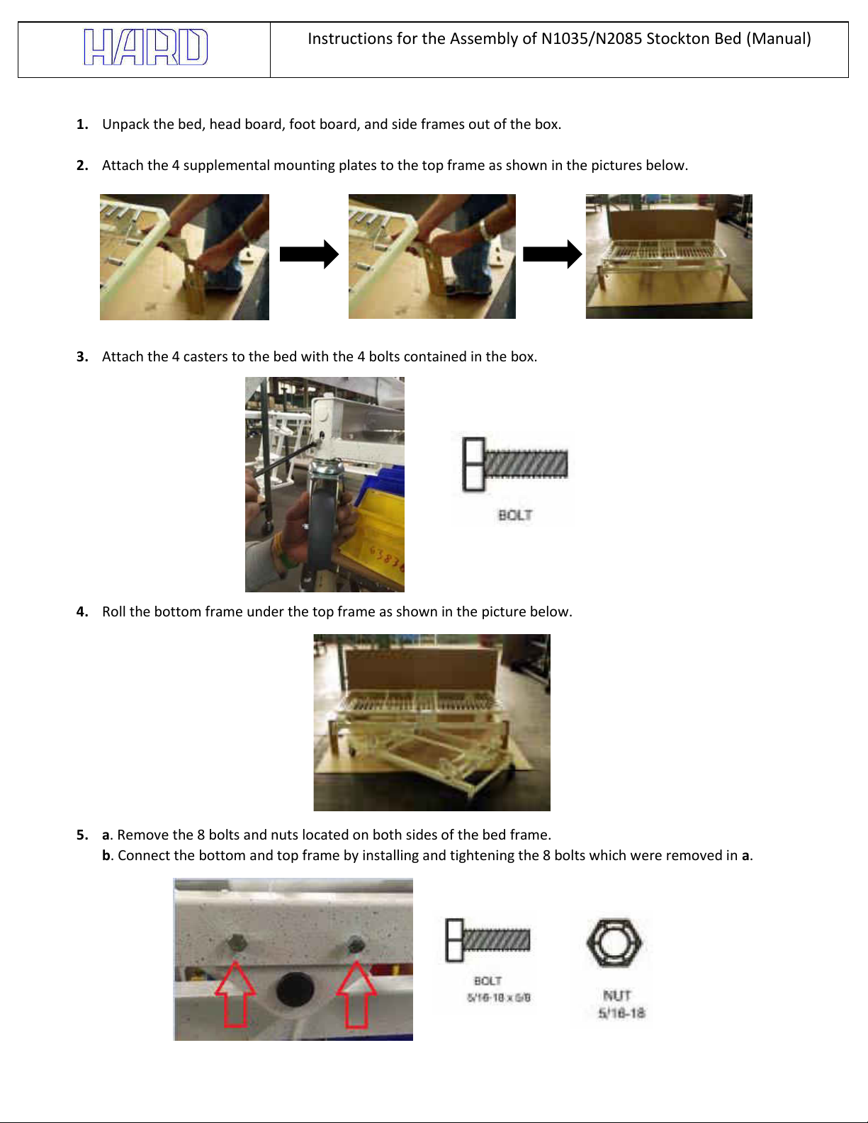
2. Attach the 4 supplemental mounting plates to the top frame as shown in the pictures below.
3. Attach the 4 casters to the bed with the 4 bolts contained in the box.
4. Roll the bottom frame under the top frame as shown in the picture below.
5. a. Remove the 8 bolts and nuts located on both sides of the bed frame.
b. Connect the bottom and top frame by installing and tightening the 8 bolts which were removed in a.
Instructions for the Assembly of N1035/N2085 Stockton Bed (Manual)

6. Remove the 4 supplemental mounting plates from the 4 corners of the bed.
7. Remove the screws for the foot and head attachment. There a total of 4 screws.
8. Attach the head and foot ends to the spring frame. Tap the corner lock on the end with a mallet and wood block
until they are firmly seated in the corner lock on the spring frame.
9. Make sure the hole of the head and foot ends align with the spring frame hole. Then using the locking screw which
was removed in step 7, screw and tighten the two components together as shown below.
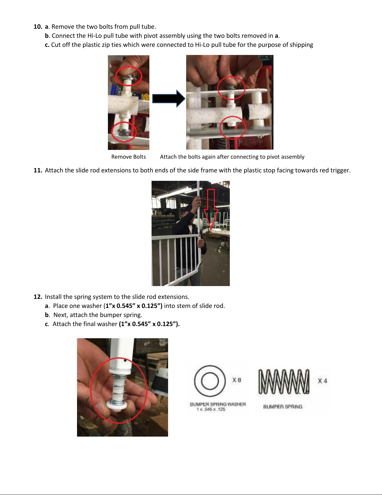
10. a. Remove the two bolts from pull tube.
b. Connect the Hi-Lo pull tube with pivot assembly using the two bolts removed in a.
c. Cut off the plastic zip ties which were connected to Hi-Lo pull tube for the purpose of shipping
Remove Bolts Attach the bolts again after connecting to pivot assembly
11. Attach the slide rod extensions to both ends of the side frame with the plastic stop facing towards red trigger.
12. Install the spring system to the slide rod extensions.
a. Place one washer (1”x 0.545” x 0.125”) into stem of slide rod.
b. Next, attach the bumper spring.
c. Attach the final washer (1”x 0.545” x 0.125”).
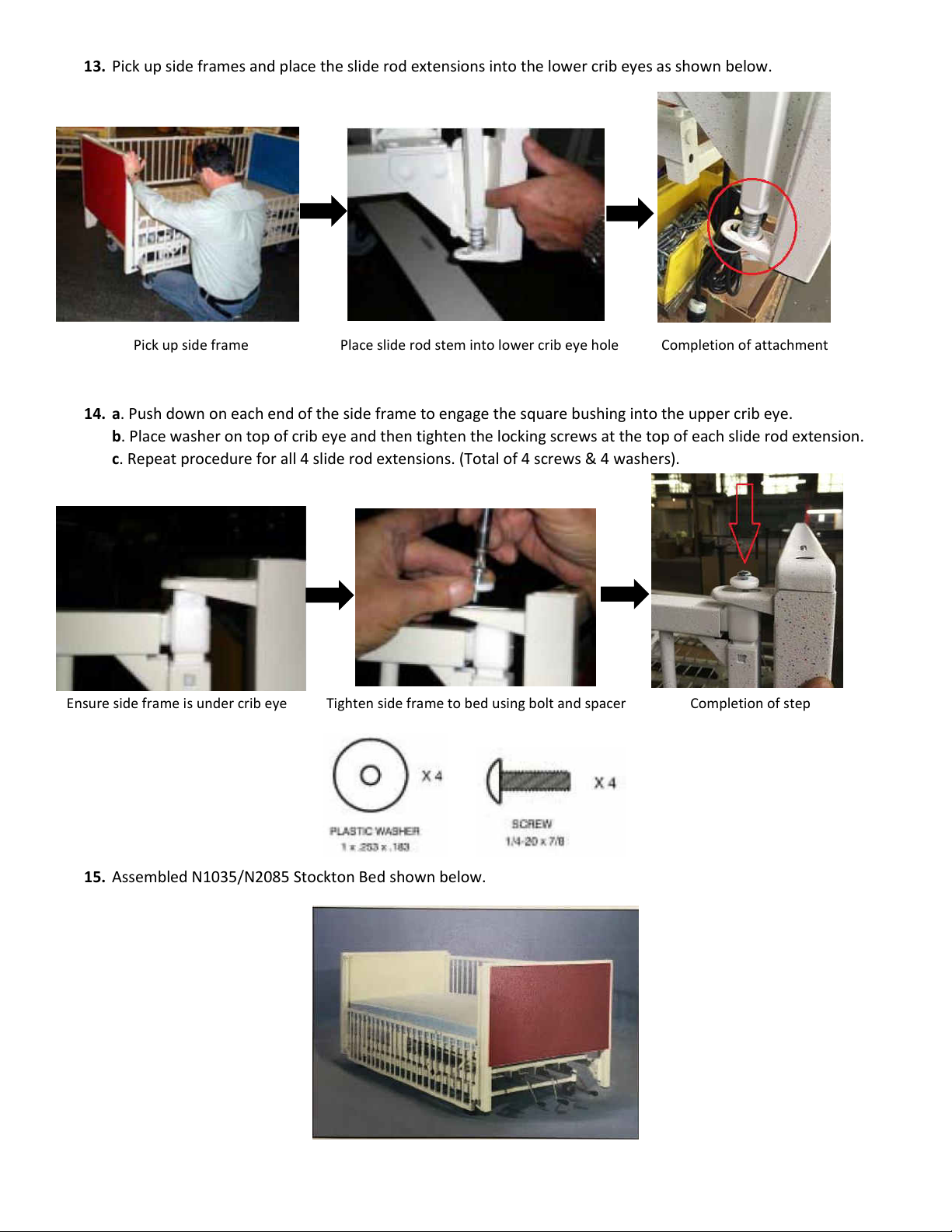
13. Pick up side frames and place the slide rod extensions into the lower crib eyes as shown below.
Pick up side frame Place slide rod stem into lower crib eye hole Completion of attachment
14. a. Push down on each end of the side frame to engage the square bushing into the upper crib eye.
b. Place washer on top of crib eye and then tighten the locking screws at the top of each slide rod extension.
c. Repeat procedure for all 4 slide rod extensions. (Total of 4 screws & 4 washers).
Ensure side frame is under crib eye Tighten side frame to bed using bolt and spacer Completion of step
15. Assembled N1035/N2085 Stockton Bed shown below.

FOR STOCKTON OR
MONROE YOUTH BEDS
The nations #1 manufacturer of hospital cribs
INSTALLATION & USAGE INSTRUCTIONS
FOR HEAVY DUTY BUMPER PADS
Revised 2020.1 3.25.2020
*1035BP fits a 36” x 72” Bed
*2085BP fits a 36” x 83” Bed

Continued on next page...
INSTALLATION OF HEAVY DUTY BUMPER PADS
You should have 4 pads. 2 are square shaped
and identical. They are used on the headboard
and footboard.
The other 2 pads are long and rectangular
shaped for the side rails and are “side
specific”. There is a tag on both side pads,
and each marked “left” or “right” The left or
right side of the bed is determind by standing
at the foot end of the bed where the crank
handles or electric staffcontrol are.
The pads should be installed without the mattress in place.
Place 1 square shaped pad against the inside surface of the headboard with the 2
white strings hanging down to the corner brackets of the spring assembly. (The corner
brackets are the areas where the mattress platform attaches to the legs of the bed)
Put the vinyl flap with the Velcro over the top edge of the headboard and affix it to the
outside face of the headboard. This secures the top of the bumper pad.
Tie offboth white strings to the corner brackets of the mattress platform. A “shoelace
bow” will suffice. This secures the bottom of the bumper pad.
Repeat these procedures for the other square shaped bumper pad for the footboard.
INSTALLING PADS ON THE HEADBOARD AND FOOTBOARD

INSTALLATION OF HEAVY DUTY BUMPER PADS- CONT.
There are white elastic straps with clips on the ends hanging from the bottom of the side pads.
Wrap this elastic band around the beam of the lower frame assembly as shown, and clip it to
itself to tie it off. Tie offthe 2 white strings on the ends of the side pads to the corner brackets
with a shoelace bow in the same manner the end pads were done.
The 3 vinyl flaps go over the top edge of the side rail and affix to the outside face of the side
rail. Be careful not to cover the 2 openings for the fingertip trigger assembly mechanisms.
With the side rail in highest position and locked in place, place one of the pads along the inside
face of the side rail with the elastic straps and white strings towards the floor.
**IMPORTANT** - The triangle shaped area on the pad (the area that doesn’t have any padding)
must go towards the head end of the bed. This triangle shaped area allows the head end of
the bed to be elevated without bunching up and interfering with the bumper pad.
INSTALLING PADS ON THE SIDERAILS
Head End
Installation of pads is complete. Mattress can
be installed/re-installed at this time.
Continued on next page...

USE OF THE RAILS WITH THE BUMPER PADS
LOWERING THE SIDERAILS WITH THE BUMPER PADS ON
**CAUTION** This procedure must be followed when lowering the siderail otherwise the
pads or Velcro may be damaged.
DO NOT TRY TO LOWER THE SIDERAIL WITHOUT FOLLOWING THESE STEPS:
Lift the 3 vinyl flaps along the entire length of the top of the side rail and then lower the side
rail. Pull the entire bumper pad towards you and allow it to fall outside the bed, while staying
attached to the bed at the bottom.
RAISING THE SIDERAILS WITH THE BUMPER PADS ON
Lift the pad up and reach down to raise the side rail. When the side rail is raised and locked
into place, reattach the 3 vinyl flaps at the top of the side rail.

The nations #1 manufacturer of hospital cribs
All bolts and other fasteners must be securely
tightened and maintained when crib is put in service.
Before each usage or assembly, inspect crib for damaged
hardware, loose joints, missing parts or sharp edges.
CAUTION SHEET

The nations #1 manufacturer of hospital cribs
Home Care Warranty
Return Policy
Acceptance of returns on all new and unused equipment and parts is at the discretion of HARD
Manufacturing. The purchaser will be responsible for a restocking fee and the freight costs associated
with returning the equipment or item.
Replacement of any part under warranty is contingent upon the following:
1. The customer is to provide the serial number of the crib or bed as well as the serial number of the
defective or damaged part(s) if one exists. If the part is a mattress, the customer must supply the
serial number of the mattress as well as photos of both tags on the mattress.
2. The customer is to provide photos of the defective or damaged part.
3. The customer must, if requested by HARD Manufacturing, return the defective or damaged item for
inspection prepaid within 30 days of reporting the issue.
Maintenance
Placing cribs and youth beds in cart washers and/or the use of steam spray guns for disinfecting is
not recommended. Use a non-abrasive cleaning solution such as a mild detergent and thoroughly
dry all components of crib or bed prior to replacing the mattress on the unit. Solvents containing
alcohol, ammonia or other abrasives should be avoided. Failure to follow the suggested cleaning/dry-
ing instructions could lead to premature corrosion and require replacement of the mattress.
Expected Service Life of HARD Manufacturing Cribs or Beds is 9 years.
Five (5) year warranty
HARD Manufacturing will replace at no cost to the purchaser any expendable component such as,
but not limited, to mattresses, trigger assemblies, slide rods or slide rod components, crank
handles, Johns Hopkins handles, vinyl curtains, curtain rods, or IV components found to have a defect
in materials or workmanship within one (1) year from the date of purchase at our discretion.
One (1) year warranty
HARD Manufacturing will replace at no cost to the purchaser any motor, staffcontrol or under
bed control box found to be defective within two (2) years from the date of purchase.
Electrical Components
Terms and Conditions of the Warranty Period
The warranty covers normal use of our cribs or youth beds. It does not cover damage or defects that
occur due to any of the following:
1. Abuse, misuse, mishandling and excessive wear by staff, patients or parents/caregivers.
2. Modifications of the equipment including the electrical equipment. The covers should never be
removed on the motors, transformers, control boxes, scale controls or staffcontrols. Doing any type
of modification to our cribs or youth beds will void the warranty.
Effective 6/1/2017 Revised 2020.1 3.26.2020
HARD Manufacturing will replace at no cost to the purchaser any non-expendable component such
as the head and foot end assemblies, side assemblies or mattress platform found to have a defect in
materials or workmanship within five (5) years from the date of purchase at our discretion.
This manual suits for next models
1


