Hardinge SUPER-PRECISION HC User manual

«*'•
■
£
,
w.
.
•
.
!
•
•
J
/
/
J
\
$
1
!
9
i
.
<n
m
MAINTENANCE
MANUAL
FOR
AUTOMATIC
THREADING
UNIT
ON
HARDINGE
SUPER-PRECISION
”
CHUCKING
MACHINE
MODELHC
mm
■

READ
MANUAL
CAREFULL
BEFORE
STARTING
MAIN
TENANCE
OR
REPAIR
ON
AUTOMATIC
THREADING
UNIT
When
this
manual
was
printed,
the
information
given
was
cur
rent.
However,
since
we
are
constantly
improving
the
design
of
our
machine
tools,
it
is
possible
that
the
illustrations
and
descriptions
may
vary
from
the
automatic
threading
unit
you
received.
This
means
that
the
unit
you
received
is
the
latest
improved
model
to
better
fulfill
your
requirements.
It
is
assumed
those
who
use
this
manual
will
have
a
general
knowledge
of
machine
maintenance
and
repair.
This
general
knowl
edge
coupled
with
the
following
manual
will
greatly
reduce
or
elimi
nate
down
time
to
allow
you
to
receive
maximum
production
from
your
Hardinge
Automatic
Threading
Unit.
HARDINGE
BROTHERS,
INC.
ELMIRA,
NEW
ORK
CONTENTS
V
PAGE
'
!
3
Air
Connections
Chasing
Head
—
Disassembly
8
11
Reassembly
:
7
Cycle
Stop
Micro
Switch
—
Replacement
6
Cylinder
Housing,
Chasing
Head
”
!
V
7
Disassembly
7
Reassembly
Electrical
Connections
4
Electric
Control
Functions
5
Feed
Rate
Adjusting
Screw
—
Removal
6
Replacement
6
A
14
Gib
Adjustment,
Tool
Post
Slide
I
Installation,
Automatic
Threading
Unit
3
Knockout
Control
—
Disassembly
14
Reassembly
15
Lubricant
Vendors
2
Lubrication
14,
19
Lubro-Control
Unit
19
Maintenance,
Preventive
2
Mounting
Bracket
and
Chasing
Bar
Assembly
18
—
i
Removal,
Automatic
Threading
Unit
5
14
Serial
Number
Slide
Travel
Adjusting
Screw
—
Removal
6
6
Replacement
5
Tool
Post
—
Disassembly
FOR
OPERATION
AND
RELATED
ADJUST ENTS,
SEE
“
OPERATOR
S
ANUAL
FOR
AUTO ATIC
THREADING
UNITS
ON
ODEL
HC
CHUCKING
ACHINES
”
1

PREVENTIVE
MAINTENANCE
DAILY
PAGE
14
Clean
and
Lubricate
Lead
Screw
and
Follower
.
14
Clean
and
Lubricate
Guide
Bar
.
WEEKL
PAGE
14
Fill
Oil
Cup
on
Chasing
Head
14
Cycle
Threading
Unit
20
Drain
Filter
Reservoir
SE I-ANNUALLY
PAGE
20
Clean
Air
Filter
Element
DEPENDING
ON
USE
PAGE
20
Maintain
Oil
in
Lubricator
Reservoir
Note:
Oil
Base
Cutting
Fluids
are
Recommended
for
Maximum
Life
of
Automatic
Threading
Unit.
LUBRICANTS
(Use
Recommended
Product
or
Equivalent)
Product
Vendor
Standard
Die
Set
Co.
(Div.
of
Dieco.)
Die
Makers
Grease
Molylube
#M-88 Alpha-Molykote
Corporation
Mobil
Oil
Corporation
Velocite
No.
6
2

I
©
©_J
Figure
1
—
Threading
Unit
Mounting
Pads
Figure
4
—
Rear
View
of
Threading
Unit
INSTALLATION
ON
EXISTING
MACHINES
1.
Remove
any
paint
or
burrs
from
pads
“
A
”
,
Fig
ure
1,
and
keyways
in
pads.
2.
Position
base
plate
“
B",
Figure
2,
and
as
semble
eight
screws
“
C
”
.
3.
Set
four
T-Bolts
“
D
”
and
“
E
”
,
Figure
3,
in
base
plate
as
shown.
Bolts
“
D
”
are
the
longer
ones
supplied.
4.
Position
threading
unit
on
base
plate
with
hoist
and
sling
and
assemble
four
washers
and
nuts
“
F
”
,
Figure
4.
DO
NOT
OVERTIGHTEN
NUTS
“
F
”
,
SNUG
IS
SUFFICIENT.
Figure
2
—
Base
Plate
Mounting
Figure
5
—
Air
Control
Unit
Location
AIR
CONNECTIONS
1.
Drill
two
3
/s"
diameter
holes
5
Vs"
apart
at
left
rear
of
oil
pan
and
mount
air
regulator
“
G
”
,
Figure
5.
2.
Fill
lubro-control
unit
with
oil
per
instructions,
Page
19.
Connect
air
line
from
threading
unit
to
lubro-control
unit.
3.
Connect
lubro-control
unit
to
air
supply.
If
ex
cessive
water
problem
exists,
add
heavy
duty
filter
to
air
line.
3

r
!
___
J
4.
Set
pressure
regulator
knob
“
J
”
,
Figure
7
to
provide
a
minimum
of
65
pounds
and
a
maximum
of
75
pounds
of
air
pressure.
Tighten
lock
screw
“
H
”
against
control
knob
to
maintain
setting.
5.
Follow
steps
1
&
2
on
this
page
under
“
Elec
trical
Connections
’
’
.
ELECTRICAL
CONNECTIONS
1.
Disconnect
power
source.
Feed
cable
“
J
”
,
Fig
ure
4,
through
hole
“
K
”
,
Figure
6.
2.
Attach
white
wire
to
terminal
8
and
black
wire
to
terminal
37
of
terminal
board.
Tighten
cable
grip
at
“
K
”
.
Figure
7
—
Lubro-Control
Unit
4

NOTE:
THREADING
UNIT
REQUIRES
ONL
10
VOLTS
FOR
OPERATION.
Machines
manufactured
after
Serial
No.
100A
are
wired
to
include
10
volt
tap
on
transformer.
FOR
INITIAL
SETTING
OF
AUTO ATIC
THREADING
UNIT,
SEE
OPERATOR
’
S
ANUAL
FOR
AUTO ATIC
THREADING
UNITS
ON
ODEL
HC
CHUCKING
ACHINE.
ELECTRIC
CONTROL
FUNCTIONS
(Figure
6)
L
—
Fuse
for
automatic
threading
unit.
(FRN
1-
1
A
)
M
—
Control
voltage
transformer
(115
volt
output
with
10
volt
tap
for
automatic
threading
unit).
Figure
10
—
Fine
Adjustment
Dial
Assembly
AUTOMATIC
THREADING
UNIT
REMOVAL
1.
Disconnect
electrical
power
source
and
remove
wires
at
terminals
8
and
37,
Figure
6.
2.
Loosen
cable
grip
at
“
K
”
and
remove
cable
from
main
switch
case.
3.
Disconnect
air
pressure
and
remove
air
line
from
threading
unit
at
lubro-control
unit.
4.
Remove
four
nuts
and
washers
“
F'\
Figure
4,
and
remove
complete
threading
unit
with
hoist
and
sling.
5.
If
necessary,
remove
the
T-Bolts
“
D
”
and
“
E
”
Figure
3,
and
base
plate
“
B
”
,
Figure
2.
TOOL
POST
DISASSEMBL
Figure
8
—
Tool
Post
Assembly
1.
Remove
bolt
“
A
”
,
Figure
8.
washer
and
tool
block
“
B
”
.
2.
Loosen
nuts
“
C
”
and
“
D",
Figure
8,
and
slide
tool
post
assembly
down
keyway
to
remove.
3.
Unscrew
fine
adjustment
dial
assembly,
Figure
9.
NOTE:
FINE
ADJUSTMENT
SCREW
HAS
LEFT-
HAND
THREADS.
4.
To
disassemble
fine
adjustment
dial
assembly:
(a)
Remove
taper
pin
“
E
”
,
Figure
10,
and
unscrew
dial
“
F
”
.
(b)
Remove
adjusting
bolt
“
G
”
,
nut
"H
”
and
T-
Bolt
“
J
”
.
5.
Remove
nut
“
K
”
,
Figure
11,
washer
and
spring
“
L
”
,
Figure
12.
Remove
T-Bolt
‘
‘
M
”
,
Figure
11.
6.
Unscrew
adjusting
nut
“
N
”
,
Figure
11,
from
tool
post
support
“
O
”
.
7.
Reassemble.
NOTE:
Fine
adjustment
dial
as
sembly
which
has
left-hand
threads,
can
be
threaded
into
either
one
of
two
threaded
holes,
depending
on
set
up.
Figure
9
—
Fine
Adjustment
Dial
Removal
5
i

r
Figure
11
—
Tool
Support
and
Components
Figure
13
—
Chasing
Head
Cylinder
Housing
Feed
Rate
Adjusting
Screw
Replacement
1.
Replace
O-ring
“
F
”
,
Figure
14,
adjusting
nut
“
E
”
,
knob
“
D
”
and
roll
pin
“
C
”
.
2.
Thread
piston
stop
assembly
“
B'\
Figure
13
into
casting
until
adjusting
nut
“
E
”
,
Figure
14,
is
flush
with
casting.
Turn
knob
“
D
”
down
until
it
just
contacts
nut
“
E
”
.
Connect
air
pressure
at
control
unit.
3.
Cycle
threading
unit.
If
unit,
fails
to
cycle
and
slide
to
advance,
turn
large
white
dial
clockwise
by
hand
to
stop
passes.
Thread
adjusting
nut
“
E
”
out
gradually
per
following
instructions
until
pawl
can
enter
ratchet
and
operate
chasing
head.
(a)
Turn
knob
“
D
’
\
Figure
14,
counter-clock
wise
until
adjusting
nut
“
E
”
moves
a
frac
tion
of
a
turn.
Tighten
set
screw
under
lock
screw
“
A
”
.
Turn
knob
“
D
”
down
until
it
just
contacts
nut
“
E
”
.
Cycle
threading
unit.
4.
When
chasing
head
cycles,
tighten
set
screw
under
lock
screw
“
A
”
,
Figure
13,
and
replace
screw
“
A
”
.
Figure
12
—
Spring
for
Tool
Post
CHASING
HEAD
C LINDER
HOUSING
Feed
Rate
Adjusting
Screw
Removal
Slide
Travel
Adjusting
Screw
Removal
1.
Disconnect
air
pressure
at
control
unit.
Loosen
set
screw
“
G
”
,
Figure
13.
Do
not
misplace
brass
plug
under
set
screw.
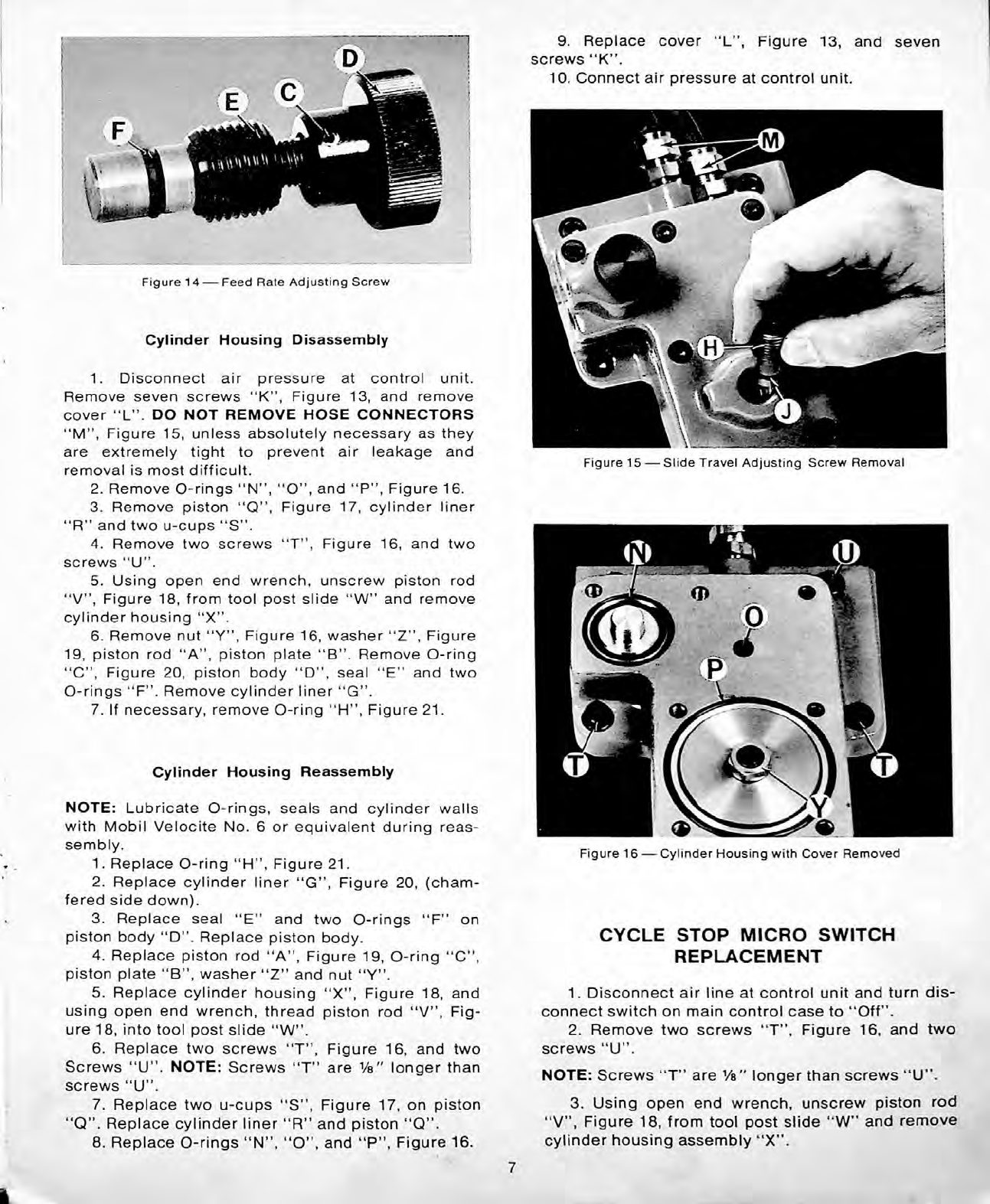
2.
Remove
adjusting
screw
“
H
”
,
Figure
15,
and
remove
O-ring
“
J
”
.
NOTE:
Feed
rate
adjusting
screw
“
B
”
,
Figure
13,
is
factory
set
and
sealed.
Removal
is
not
recommended
unless
absolutely
necessary.
1.
Disconnect
air
pressure
at
control
unit.
Remove
wax
seal
from
screw
“
A
”
,
Figure
13,
and
remove
lock
screw
“
A
”
.
Loosen
set
screw
under
lock
screw
“
A
”
.
2.
Unscrew
piston
stop
assembly
“
B
”
.
Remove
roll
pin
“
C
”
,
Figure
14,
knob
“
D
”
,
adjusting
nut
“
E
”
and
O-ring
“
F
”
.
Do
not
misplace
brass
plug
under
screws
“
A
”
,
Figure
13.
Slide
Travel
Adjusting
Screw
Replacement
1.
Replace
O-ring
“
J
”
,
Figure
15,
and
start
ad
justing
screw
“
H
”
.
Connect
air
pressure
at
control
unit.
2.
Set
thread
depth
control
dial
at
70.
Turn
ad
justing
screw
“
H
”
,
Figure
15,
slowly
to
its
limit
under
normal
pressure
and
back
off
Vs
turn.
Relock
set
screw
“
G
”
,
Figure
13.
6
9.
Replace
cover
“
L
”
,
Figure
13,
and
seven
screws
“
K
”
.
10.
Connect
air
pressure
at
control
unit.
:
Figure
14
—
Feed
Rate
Adjusting
Screw
Cylinder
Housing
Disassembly
1.
Disconnect
air
pressure
at
control
unit.
Remove
seven
screws
“
K
”
,
Figure
13,
and
remove
cover
“
L
”
.
DO
NOT
REMOVE
HOSE
CONNECTORS
“
M
”
,
Figure
15,
unless
absolutely
necessary
as
they
are
extremely
tight
to
prevent
air
leakage
and
removal
is
most
difficult.
2.
Remove
O-rings
“
N
”
,
“
O
”
,
and
“
P
”
,
Figure
16.
3.
Remove
piston
“
Q
”
,
Figure
17,
cylinder
liner
“
R
”
and
two
u-cups
“
S
”
.
4.
Remove
two
screws
“
T
”
,
Figure
16,
and
two
screws
“
U
”
.
5.
Using
open
end
wrench,
unscrew
piston
rod
“
V
”
,
Figure
18,
from
tool
post
slide
“
W
”
and
remove
cylinder
housing
“
X
”
.
6.
Remove
nut
“
”
,
Figure
16,
washer
“
Z
”
,
Figure
19,
piston
rod
“
A
”
,
piston
plate
“
B
”
.
Remove
O-ring
“
C
”
,
Figure
20,
piston
body
“
D
”
,
seal
“
E
”
and
two
O-rings
“
F
”
.
Remove
cylinder
liner
“
G
”
.
7.
If
necessary,
remove
O-ring
“
H
”
,
Figure
21.
Figure
15
—
Slide
Travel
Adjusting
Screw
Removal
Cylinder
Housing
Reassembly
NOTE:
Lubricate
O-rings,
seals
and
cylinder
walls
with
Mobil
Velocite
No.
6
or
equivalent
during
reas
sembly.
1.
Replace
O-ring
“
H
”
,
Figure
21.
2.
Replace
cylinder
liner
“
G
”
,
Figure
20,
(cham
fered
side
down).
3.
Replace
seal
“
E
”
and
two
O-rings
“
F
piston
body
“
D
”
.
Replace
piston
body.
4.
Replace
piston
rod
“
A
”
,
Figure
19,
O-ring
“
C
”
,
piston
plate
“
B
”
,
washer
“
Z
”
and
nut
“
".
5.
Replace
cylinder
housing
“
X
”
,
Figure
18,
and
using
open
end
wrench,
thread
piston
rod
“
V
”
,
Fig
ure
18,
into
tool
post
slide
“
W
”
.
6.
Replace
two
screws
“
T
”
,
Figure
16,
and
two
Screws
“
U
”
.
NOTE:
Screws
“
T
”
are
Vs"
longer
than
screws
“
U
”
.
7.
Replace
two
u-cups
“
S
”
,
Figure
17,
on
piston
“
Q
”
.
Replace
cylinder
liner
“
R
”
and
piston
“
Q
”
.
8.
Replace
O-rings
“
N
”
,
“
O
”
,
and
“
P
”
,
Figure
16.
Figure
16
—
Cylinder
Housing
with
Cover
Removed
on
C CLE
STOP
MICRO
SWITCH
REPLACEMENT
1.
Disconnect
air
line
at
control
unit
and
turn
dis
connect
switch
on
main
control
case
to
“
Off
”
.
2.
Remove
two
screws
“
T
”
,
Figure
16,
and
two
screws
“
U
”
.
NOTE:
Screws
“
T
”
are
Vs"
longer
than
screws
“
U
”
.
3.
Using
open
end
wrench,
unscrew
piston
rod
“
V
”
,
Figure
18,
from
tool
post
slide
“
W
”
and
remove
cylinder
housing
assembly
“
X
”
.
7
i

Wi
v?l|
4.
Remove
two
screws
“
B
”
,
Figure
22,
and,
remove
micro
switch
“
A
”
.
Remove
wires
from
micro
switch.
5.
Connect
wires
to
normally
closed
and
common
terminals
of
new
micro
switch.
Replace
switch
“
A
”
and
two
screws
“
B
”
.
Do
not
tighten
screws.
6.
Pull
cycle
start
knob,
set
micro
switch
with
ac
tivator
just
touching
plunger
“
C
”
and
tighten
screws
“
B
”
.
7.
Turn
disconnect
switch
on
main
control
case
to
“
On
”
.
When
threading
unit
is
lowered
to
operating
position
a
click
will
be
heard
from
solenoid
in
knockout
housing
with
cycle
start
knob
“
Out
”
and
will
not
be
heard
with
cycle
start
knob
“
In
”
,
if
micro
switch
“
A
”
is
operating
properly.
Turn
large
white
dial
right-handed
to
retract
cycle
start
knob.
8.
Reassemble
other
components
by
reversing
steps
1,2,
and
3.
Figure
19
—
Piston
for
Slide
Travel
Adjusting
Screw
Figure
20
—
Cylinder
Housing
and
Components
Figure
17
—
Piston
for
Feed
Rate
Adjusting
Screw
Figure
21
—
Cylinder
Housing
CHASING
HEAD
DISASSEMBL
1.
Support
guide
bar
bracket
“
F
”
,
Figure
23,
by
hand
and
loosen
two
bolts
“
G
”
.
Remove
guide
bar
bracket.
2.
Follow
steps
1,
2,
and
3
under
“
Cycle
Stop
Micro
Switch
Replacement
”
on
previous
page.
3.
Remove
two
screws
“
B
”
,
Figure
22,
and
remove
micro
switch
“
A
”
.
Remove
wires
from
micro
switch.
Remove
O-ring
seal
for
micro
switch.
Figure
18
—
Piston
Rod
for
Slide
Travel
8
:
7]
r>
x\M
E
b
^
'
m
Figure
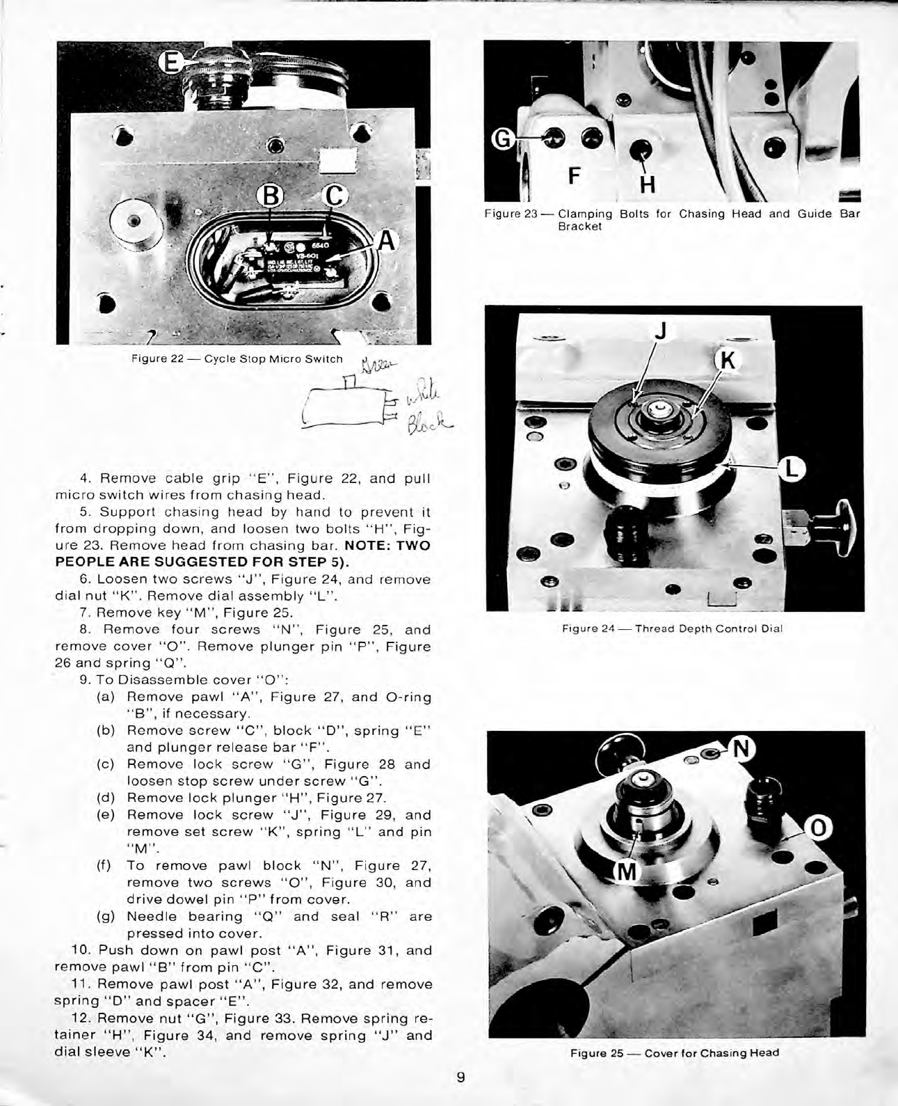
23
—
Clamping
Bolts
for
Chasing
Head
and
Guide
Bar
Bracket
w':
I
*
•
.
:
.
7
--^11
Figure
22
—
Cycle
Stop
Micro
Switch
■
n
i
4.
Remove
cable
grip
“
E
”
,
Figure
22,
and
pull
micro
switch
wires
from
chasing
head.
5.
Support
chasing
head
by
hand
to
prevent
it
from
dropping
down,
and
loosen
two
bolts
“
H
”
,
Fig
ure
23.
Remove
head
from
chasing
bar.
NOTE:
TWO
PEOPLE
ARE
SUGGESTED
FOR
STEP
5).
6.
Loosen
two
screws
“
J
”
,
Figure
24,
and
remove
dial
nut
“
K
”
.
Remove
dial
assembly
“
L
”
.
7.
Remove
key
“
M
”
,
Figure
25.
8.
Remove
four
screws
“
N
”
,
Figure
25,
and
remove
cover
“
O".
Remove
plunger
pin
“
P
”
,
Figure
26
and
spring
“
Q
”
.
9.
To
Disassemble
cover
“
O
”
:
(a)
Remove
pawl
“
A
”
,
Figure
27,
and
O-ring
“
B
”
,
if
necessary.
(b)
Remove
screw
“
C
”
,
block
“
D
”
,
spring
“
E
”
and
plunger
release
bar
“
F
”
.
(c)
Remove
lock
screw
“
G
”
,
Figure
28
and
loosen
stop
screw
under
screw
“
G
”
.
(d)
Remove
lock
plunger
“
H
”
,
Figure
27.
(e)
Remove
lock
screw
“
J
”
,
Figure
29,
and
remove
set
screw
“
K",
spring
“
L
”
and
pin
“
”
.
(f)
To
remove
pawl
block
“
N
”
,
Figure
27,
remove
two
screws
“
O
”
,
Figure
30,
and
drive
dowel
pin
“
P
”
from
cover.
(g)
Needle
bearing
“
Q
”
and
seal
“
R
”
are
pressed
into
cover.
10.
Push
down
on
pawl
post
“
A
”
,
Figure
31,
and
remove
pawl
“
B
”
from
pin
“
C
,
\
11.
Remove
pawl
post
“
A
”
,
Figure
32,
and
remove
spring
“
D
”
and
spacer
“
E
”
.
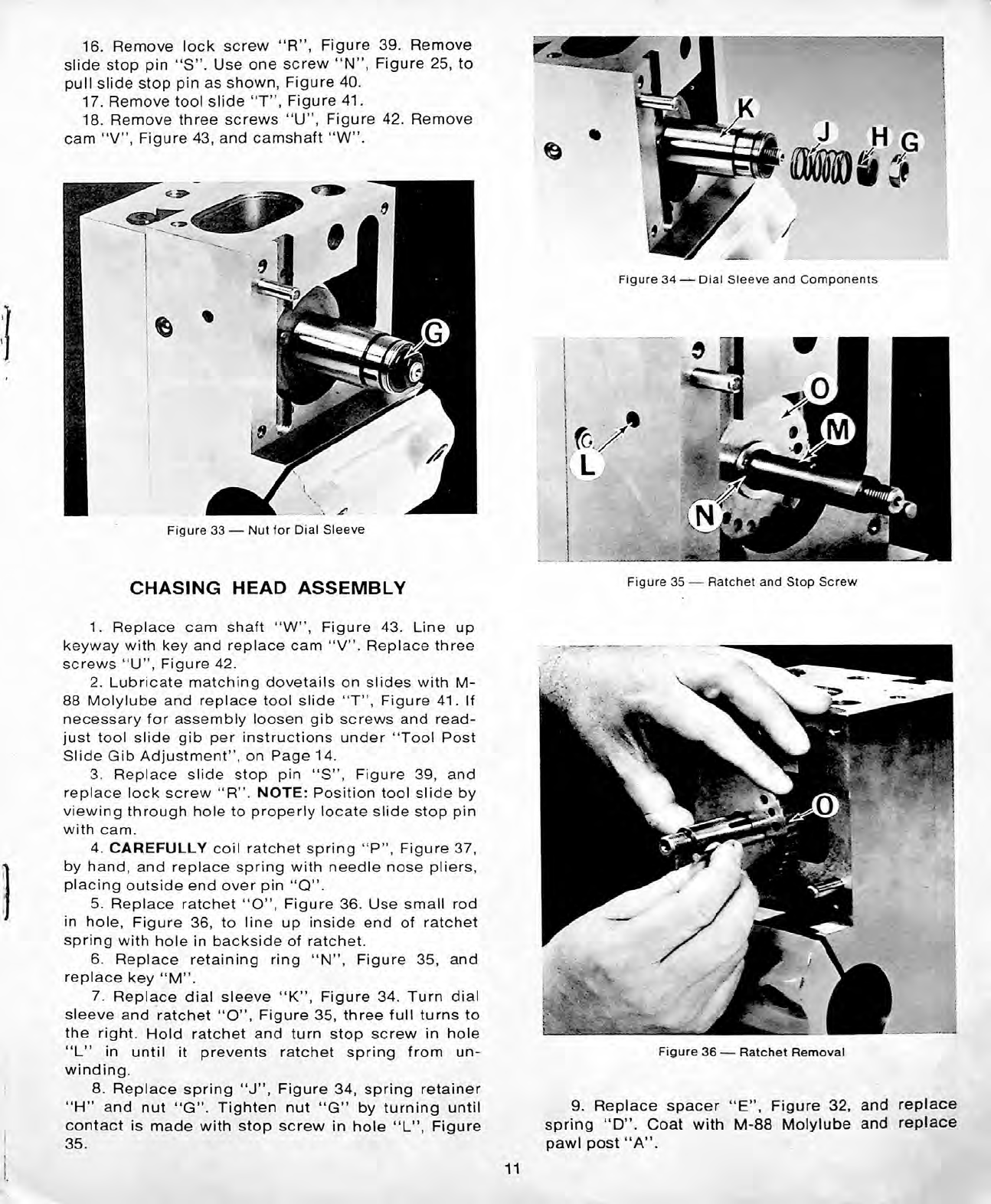
12.
Remove
nut
“
G
”
,
Figure
33.
Remove
spring
re
tainer
“
H
”
,
Figure
34,
and
remove
spring
“
J
”
and
dial
sleeve
“
K
”
.
Figure
24
—
Thread
Depth
Control
Dial
Figure
25
—
Cover
for
Chasing
Head
9
r
i
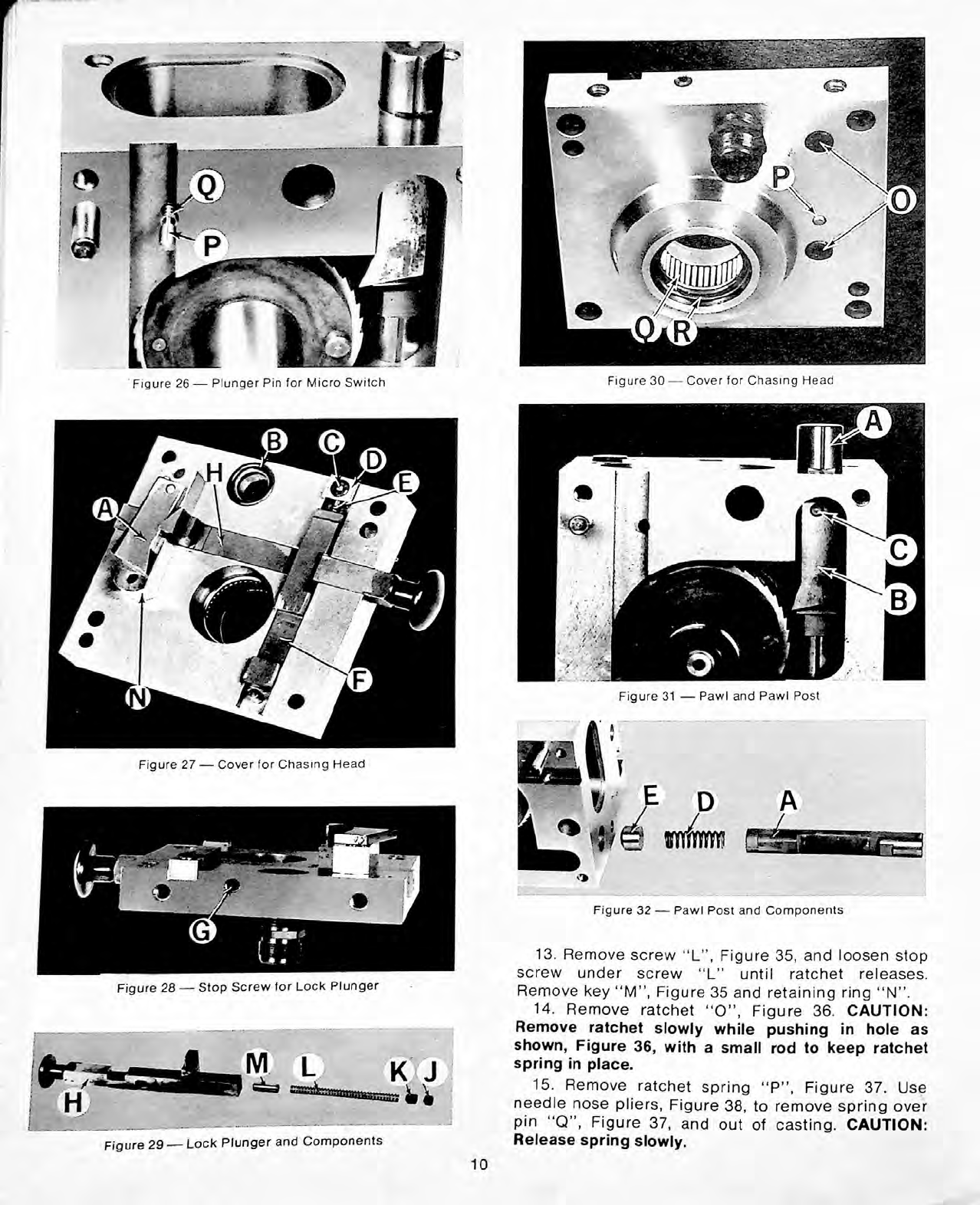
Figure
30
—
Cover
for
Chasing
Head
'
Figure
26
—
Plunger
Pin
for
Micro
Switch
C
B
•s-
-
Figure
31
—
Pawl
and
Pawl
Post
ft
mi
’
*
Figure
27
—
Cover
for
Chasing
Head
}
V
j-
p
A
Figure
32
—
Pawl
Post
and
Components
13.
Remove
screw
“
L
”
,
Figure
35,
and
loosen
stop
screw
under
screw
“
L
”
until
ratchet
releases.
Remove
key
“
M
”
,
Figure
35
and
retaining
ring
“
N
”
.
14.
Remove
ratchet
“
O
”
,
Figure
36.
CAUTION:
Remove
ratchet
slowly
while
pushing
in
hole
as
shown,
Figure
36,
with
a
small
rod
to
keep
ratchet
spring
in
place.
15.
Remove
ratchet
spring
“
P
”
,
Figure
37.
Use
needle
nose
pliers,
Figure
38,
to
remove
spring
over
pin
“
Q
”
,
Figure
37,
and
out
of
casting.
CAUTION:
Release
spring
slowly.
Figure
28
—
Stop
Screw
for
Lock
Plunger
L
K
J
SSSS!
k
:
ffi3ffiaaBaEas;
^
^
Figure
29
—
Lock
Plunger
and
Components
10
16.
Remove
lock
screw
“
R
”
,
Figure
39.
Remove
slide
stop
pin
“
S
”
.
Use
one
screw
“
N
”
,
Figure
25,
to
pull
slide
stop
pin
as
shown,
Figure
40.
17.
Remove
tool
slide
“
T
”
,
Figure
41.
18.
Remove
three
screws
“
U
”
,
Figure
42.
Remove
cam
“
V
”
,
Figure
43,
and
camshaft
“
W
”
.
Figure
34
—
Dial
Sleeve
and
Components
Figure
33
—
Nut
for
Dial
Sleeve
Figure
35
—
Ratchet
and
Stop
Screw
CHASING
HEAD
ASSEMBL
1.
Replace
cam
shaft
“
W
”
,
Figure
43.
Line
up
keyway
with
key
and
replace
cam
“
V
”
.
Replace
three
screws
“
U
”
,
Figure
42.
2.
Lubricate
matching
dovetails
on
slides
with
M-
88
Molylube
and
replace
tool
slide
“
T
”
,
Figure
41.
If
necessary
for
assembly
loosen
gib
screws
and
read
just
tool
slide
gib
per
instructions
under
“
Tool
Post
Slide
Gib
Adjustment
”
,
on
Page
14.
3.
Replace
slide
stop
pin
“
S
”
,
Figure
39,
and
replace
lock
screw
“
R
”
.
NOTE:
Position
tool
slide
by
viewing
through
hole
to
properly
locate
slide
stop
pin
with
cam.
4.
CAREFULLY
coil
ratchet
spring
“
P
”
,
Figure
37,
by
hand,
and
replace
spring
with
needle
nose
pliers,
placing
outside
end
over
pin
“
Q
”
.
5.
Replace
ratchet
“
O
”
,
Figure
36.
Use
small
rod
in
hole,
Figure
36,
to
line
up
inside
end
of
ratchet
spring
with
hole
in
backside
of
ratchet.
6.
Replace
retaining
ring
“
N
”
,
Figure
35,
and
replace
key
“
M
”
.
7.
Replace
dial
sleeve
“
K
”
,
Figure
34.
Turn
dial
sleeve
and
ratchet
“
O
”
,
Figure
35,
three
full
turns
to
the
right.
Hold
ratchet
and
turn
stop
screw
in
hole
“
L
”
in
until
it
prevents
ratchet
spring
from
un
winding.
8.
Replace
spring
“
J
”
,
Figure
34,
spring
retainer
“
H
”
and
nut
“
G
”
.
Tighten
nut
“
G
”
by
turning
until
contact
is
made
with
stop
screw
in
hole
“
L
”
,
Figure
Figure
36
—
Ratchet
Removal
9.
Replace
spacer
“
E
”
,
Figure
32,
and
replace
spring
“
D
”
.
Coat
with
M-88
Molylube
and
replace
pawl
post
“
A
”
.
35.
11

V
Figure
40
—
Slide
Stop
Pin
Removal
Figure
37
—
Ratchet
Spring
Figure
38
—
Ratchet
Spring
Removal
Figure
41
—
Tool
Post
Slide
Removal
Figure
39
—
Lock
Screw
and
Slide
Stop
Pin
for
Tool
Post
Slide
Figure
42
—
Mounting
Screws
for
Cam
12
10.
Coat
pawl
“
B
”
,
Figure
31,
with
M-88
Molylube
and
replace.
11.
To
reassemble
cover
"O
”
,
Figure
25:
(a)
If
removed,
press
needle
bearing
“
Q
”
,
Fig
ure
30,
and
seal
“
R
”
in
cover.
(b)
If
removed,
replace
pawl
block
“
N
”
,
Figure
27,
dowel
pin
“
P
”
,
and
two
screws
“
O
”
,
Figure
30.
(c)
Coat
with
M-88
Molylube
and
replace
lock
plunger
“
H
”
,
Figure
27.
Turn
stop
screw
in
hole
“
G
”
,
Figure
28,
into
elongated
slot
in
plunger
“
H
”
,
Figure
29.
Bottom
stop
screw
and
back
off
approximately
one
turn.
Replace
lock
screw
“
G
”
,
Figure
28.
(d)
Replace
pin
“
M
”
,
Figure
29,
spring
“
L
”
and
screw
“
K
”
.
(e)
Coat
plunger
release
bar
“
F
”
,
Figure
27,
with
M-88
Molylube
and
replace.
Replace
spring
“
E
”
,
block
“
D
”
,
and
screw
“
C
”
.
(f)
Replace
O-ring
“
B
”
.
Coat
with
M-88
and
replace
pawl
“
A
”
.
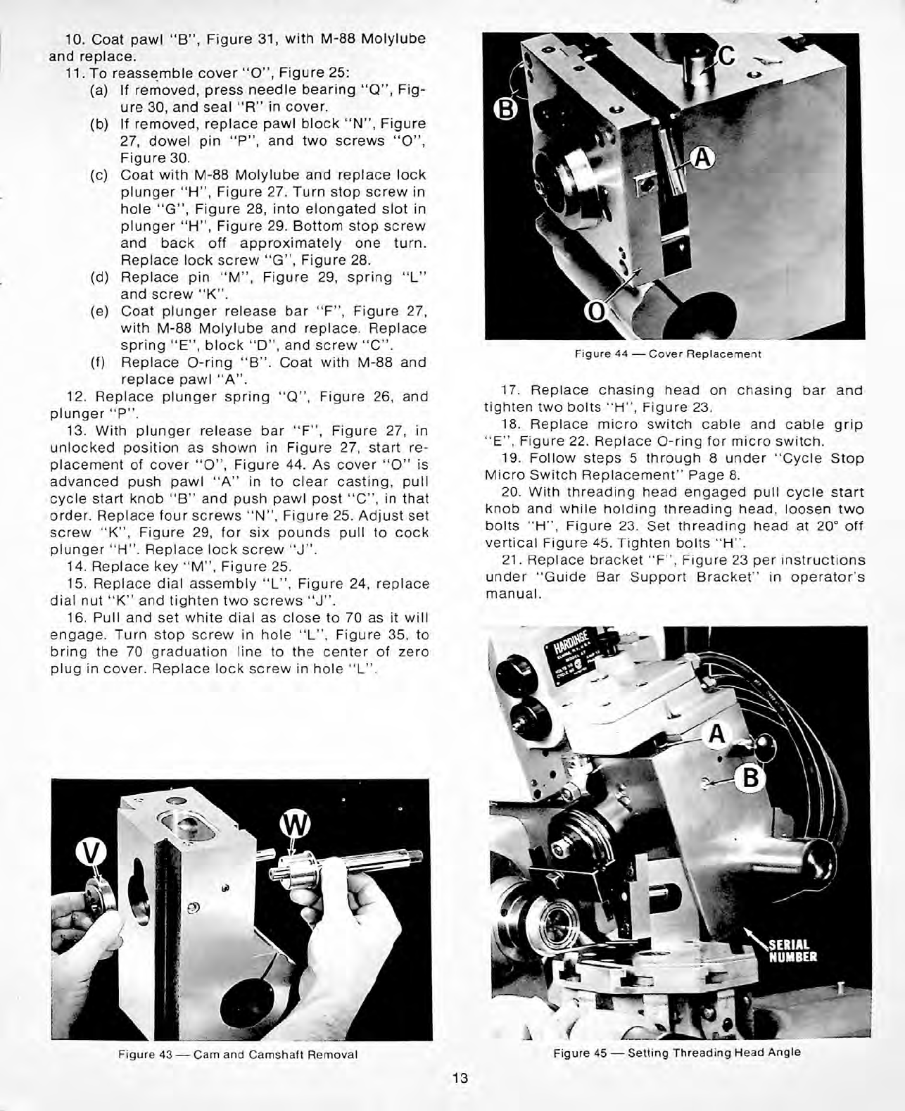
12.
Replace
plunger
spring
“
Q
”
,
Figure
26,
and
plunger
“
P
”
.
13.
With
plunger
release
bar
“
F
”
,
Figure
27,
in
unlocked
position
as
shown
in
Figure
27,
start
re
placement
of
cover
“
O
”
,
Figure
44.
As
cover
“
O
”
is
advanced
push
pawl
“
A
”
in
to
clear
casting,
pull
cycle
start
knob
“
B
”
and
push
pawl
post
“
C
”
,
in
that
order.
Replace
four
screws
“
N
”
,
Figure
25.
Adjust
set
screw
“
K
”
,
Figure
29,
for
six
pounds
pull
to
cock
plunger
“
H
”
.
Replace
lock
screw
“
J
”
.
14.
Replace
key
“
M
”
,
Figure
25.
15.
Replace
dial
assembly
“
L
”
,
Figure
24,
replace
dial
nut
“
K
”
and
tighten
two
screws
“
J
”
.
16.
Pull
and
set
white
dial
as
close
to
70
as
it
will
engage.
Turn
stop
screw
in
hole
“
L
”
,
Figure
35,
to
bring
the
70
graduation
line
to
the
center
of
zero
plug
in
cover.
Replace
lock
screw
in
hole
“
L
”
.
Figure
44
—
Cover
Replacement
17.
Replace
chasing
head
on
chasing
bar
and
tighten
two
bolts
“
H
”
,
Figure
23.
18.
Replace
micro
switch
cable
and
cable
grip
“
E
”
,
Figure
22.
Replace
O-ring
for
micro
switch.
19.
Follow
steps
5
through
8
under
“
Cycle
Stop
Micro
Switch
Replacement
”
Page
8.
20.
With
threading
head
engaged
pull
cycle
start
knob
and
while
holding
threading
head,
loosen
two
bolts
“
H
”
,
Figure
23.
Set
threading
head
at
20°
off
vertical
Figure
45.
Tighten
bolts
“
H
”
.
21.
Replace
bracket
“
F
”
.
Figure
23
per
instructions
under
“
Guide
Bar
Support
Bracket
”
in
operator
’
s
manual.
Figure
45
—
Setting
Threading
Head
Angle
Figure
43
—
Cam
and
Camshaft
Removal
13
4.
Remove
four
screws
“
D
”
,
Figure
49,
and
remove
valve
housing
over
two
dowel
pins
“
E
”
.
5.
Remove
screw
“
F
”
,
Figure
50,
and
white
wire.
Remove
black
wire
from
“
common
”
terminal
on
micro
switch
“
G
”
.
6.
Remove
wire
from
terminal
screw
“
J
”
and
remove
wire
from
“
normally
open
”
terminal
on
micro
switch
“
G
”
.
7.
If
necessary,
remove
two
O-rings
“
K
”
.
8.
To
remove
air
valve
“
L
”
:
(a)
Remove
red
wire
from
terminal
“
M
”
,
Fig
ure
51.
(b)
Remove
three
remaining
screws
“
F
”
,
Fig
ure
50,
and
remove
air
valve.
(c)
Remove
coupling
“
N
”
,
felt
“
O
”
,
washer
“
P
”
,
spring
“
Q
”
and
nipple
“
R
”
.
(d)
Remove
exhaust
silencer
“
S
”
,
coupling
“
T
”
,
nipple
“
U
”
and
elbow
“
V
”
.
9.
To
remove
micro
switches:
(a)
Remove
remaining
wires
from
micro
switches.
(b)
Remove
two
screws,
nuts
and
washers
“
W
”
,
Figure
52,
and
remove
micro
switches
“
G
”
and
“
H
”
,
Figure
50.
TOOL
POST
SLIDE
GIB
ADJUSTMENT
After
considerable
use
it
may
be
necessary
to
ad
just
the
tool
post
slide
gib.
The
gib
is
the
tapered
type
and
adjustment
is
made
from
the
large
end
shown
in
Figure
45.
1.
Follow
steps
2
and
16
under
“
Chasing
Head
Disassembly
”
,
Page
8.
2.
Insert
V
a
"
hexagon
wrench
in
adjusting
screw
“
A
”
,
Figure
45
and
Figure
46.
Loosen
one
full
turn.
3.
Push
wrench
on
through
into
adjusting
screw
“
B
”
,
Figure
46.
Advance
adjusting
screw
“
B
”
a
frac
tion
of
a
turn.
4.
Pull
wrench
out
of
“
B
”
and
tighten
“
A
”
until
snug.
Do
not
overtighten.
5.
Test
tool
slide
for
“
feel
”
—
the
slide
should
have
a
slight
drag
but
should
not
bind.
NOTE:
Excessive
gib
pressure
or
drag
does
not
improve
performance.
LUBRICATION
LUBRICATE
LEAD
SCREW
AND
FOLLOWER
with
Die
Makers
Grease.
Clean
lead
screw
and
follower
daily
during
a
production
run
and
relubricate.
OIL
CUP
“
B
”
,
Figure
45,
ON
SIDE
OF
CHASING
HEAD
should
be
filled
weekly
with
Mobil
Velocite
No.
6
for
lubrication
of
slide
stop
pin
and
cam.
For
proper
lubrication,
AUTOMATIC
THREADING
UNIT
SHOULD
BE
C CLED
AT
LEAST
ONCE
A
WEEK
when
not
in
regular
use.
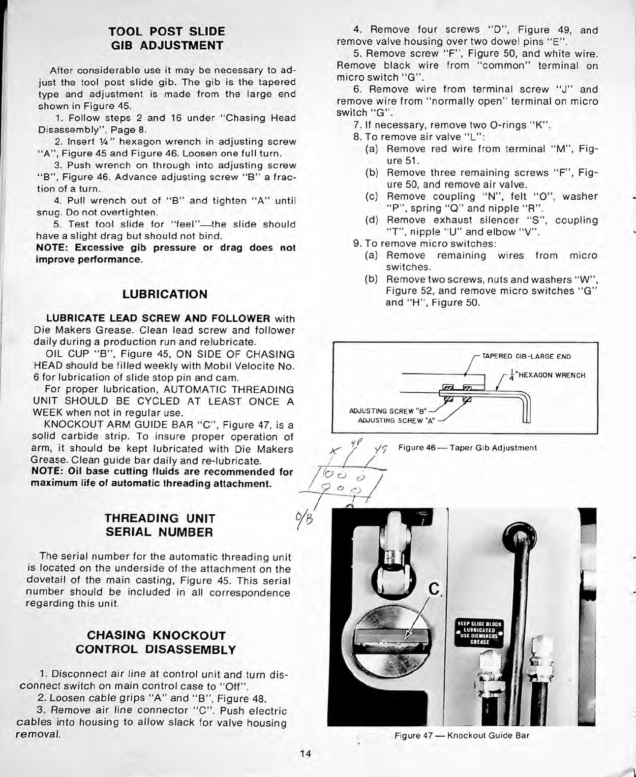
KNOCKOUT
ARM
GUIDE
BAR
“
C
”
,
Figure
47,
is
a
solid
carbide
strip.
To
insure
proper
operation
of
arm,
it
should
be
kept
lubricated
with
Die
Makers
Grease.
Clean
guide
bar
daily
and
re-lubricate.
NOTE:
Oil
base
cutting
fluids
are
recommended
for
maximum
life
of
automatic
threading
attachment.
TAPERED
GIB-LARGE
END
HEXAGON
WRENCH
\rri
RrT
ADJUSTING
SCREW
"B"
ADJUSTING
SCREW
"A"
if
Figure
46
—
Taper
Gib
Adjustment
/
THREADING
UNIT
SERIAL
NUMBER
The
serial
number
for
the
automatic
threading
unit
is
located
on
the
underside
of
the
attachment
on
the
dovetail
of
the
main
casting,
Figure
45.
This
serial
number
should
be
included
in
all
correspondence
regarding
this
unit.
CHASING
KNOCKOUT
CONTROL
DISASSEMBL
1.
Disconnect
air
line
at
control
unit
and
turn
dis
connect
switch
on
main
control
case
to
“
Off
”
.
2.
Loosen
cable
grips
“
A
”
and
“
B
”
,
Figure
48.
3.
Remove
air
line
connector
“
C
”
.
Push
electric
cables
into
housing
to
allow
slack
for
valve
housing
remo al.
14
i
11.
To
remove
guide
bar
and
knockout
piston:
(a)
Remove
set
screw
“
A
”
,
Figure
55.
Remove
adjusting
collar
“
B
”
.
DO
NOT
ISPLACE
BRASS
PLUG
under
set
screw
“
A
”
.
(b) Use
face
spanner
wrench
to
remove
nut
“
C
”
.
(c)
Remove
spring
“
D
”
,
Figure
56,
and
remove
nut
“
E'\
Figure
57.
(d)
Remove
piston
shaft
“
F
”
,
Figure
58.
(e)
If
necessary,
loosen
two
screws
“
G
”
and
drive
out
pin
"H"
to
remove
guide
bar
“
J
”
.
(f)
Remove
piston
plate
“
K
”
,
Figure
59,
O-ring
“
L
”
,
piston-ring
“
M
”
,
seal
“
N
”
and
O-ring
“
O
”
.
(g)
Remove
O-ring
“
P",
Figure
60,
if
neces
sary.
12.
To
remove
roller
clamp
piston:
(a)
Use
face
spanner
wrench
to
remove
nut
“
Q
”
,
Figure
55.
Remove
spring
“
R
”
,
Figure
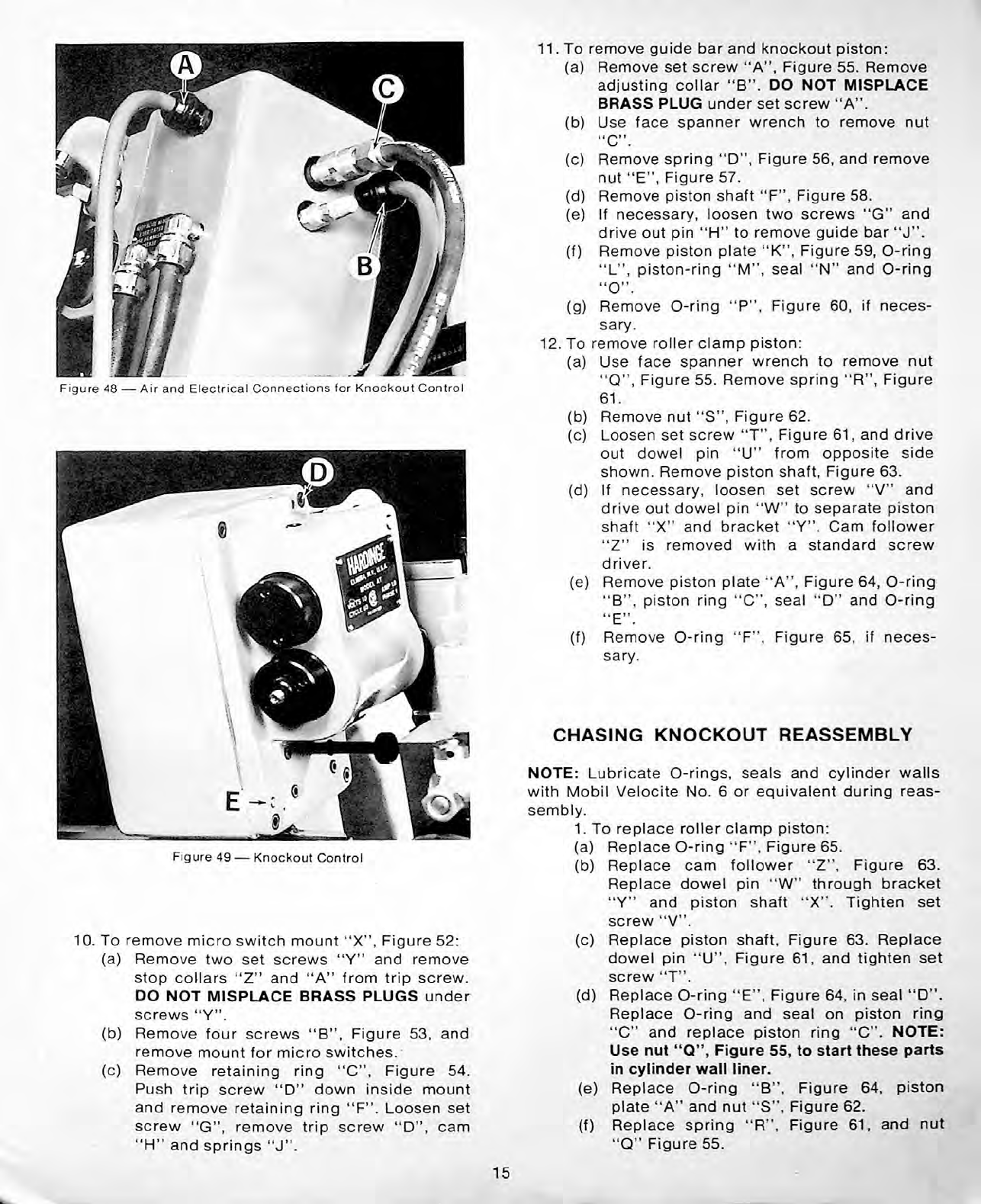
Figure
48
—
Air
and
Electrical
Connections
for
Knockout
Control
61.
(b)
Remove
nut
“
S
”
,
Figure
62.
(c)
Loosen
set
screw
“
T
”
,
Figure
61,
and
drive
out
dowel
pin
“
U
”
from
opposite
side
shown.
Remove
piston
shaft,
Figure
63.
(d)
If
necessary,
loosen
set
screw
“
V
”
and
drive
out
dowel
pin
“
W
”
to
separate
piston
shaft
“
X
”
and
bracket
“
”
.
Cam
follower
is
removed
with
a
standard
screw
“
Z
driver.
(e)
Remove
piston
plate
'
‘
A
”
,
Figure
64,
O-ring
“
B
”
,
piston
ring
“
C
”
,
seal
“
D
”
and
O-ring
“
E
”
.
(f)
Remove
O-ring
“
F
”
,
Figure
65,
if
neces
sary.
CHASING
KNOCKOUT
REASSEMBL
NOTE:
Lubricate
O-rings,
seals
and
cylinder
walls
with
Mobil
Velocite
No.
6
or
equivalent
during
reas
sembly.
1.
To
replace
roller
clamp
piston:
(a)
Replace
O-ring
“
F
”
,
Figure
65.
(b)
Replace
cam
follower
“
Z
”
,
Figure
63.
Replace
dowel
pin
“
W
”
through
bracket
“
”
and
piston
shaft
“
X
”
.
Tighten
set
screw
“
V
”
.
(c)
Replace
piston
shaft,
Figure
63.
Replace
dowel
pin
“
U
”
,
Figure
61,
and
tighten
set
screw
“
T
”
.
(d)
Replace
O-ring
“
E
”
,
Figure
64,
in
seal
“
D
M
.
Replace
O-ring
and
seal
on
piston
ring
“
C
”
and
replace
piston
ring
“
C
”
.
NOTE:
Use
nut
“
Q
”
,
Figure
55,
to
start
these
parts
in
cylinder
wall
liner.
(e)
Replace
O-ring
“
B
”
,
Figure
64,
piston
plate
“
A
”
and
nut
“
S
”
,
Figure
62.
(f)
Replace
spring
“
R
”
,
Figure
61,
and
nut
“
Q
”
Figure
55.
Figure
49
—
Knockout
Control
10.
To
remove
micro
switch
mount
“
X
”
,
Figure
52:
(a)
Remove
two
set
screws
“
”
and
remove
stop
collars
“
Z
”
and
“
A
”
from
trip
screw.
DO
NOT
ISPLACE
BRASS
PLUGS
under
screws
“
”
.
(b)
Remove
four
screws
“
B
”
,
Figure
53,
and
remove
mount
for
micro
switches.
(c)
Remove
retaining
ring
“
C
”
,
Figure
54.
Push
trip
screw
“
D
”
down
inside
mount
and
remove
retaining
ring
“
F
”
.
Loosen
set
screw
“
G
”
,
remove
trip
screw
“
D
”
,
cam
“
H
”
and
springs
“
J
”
.
15
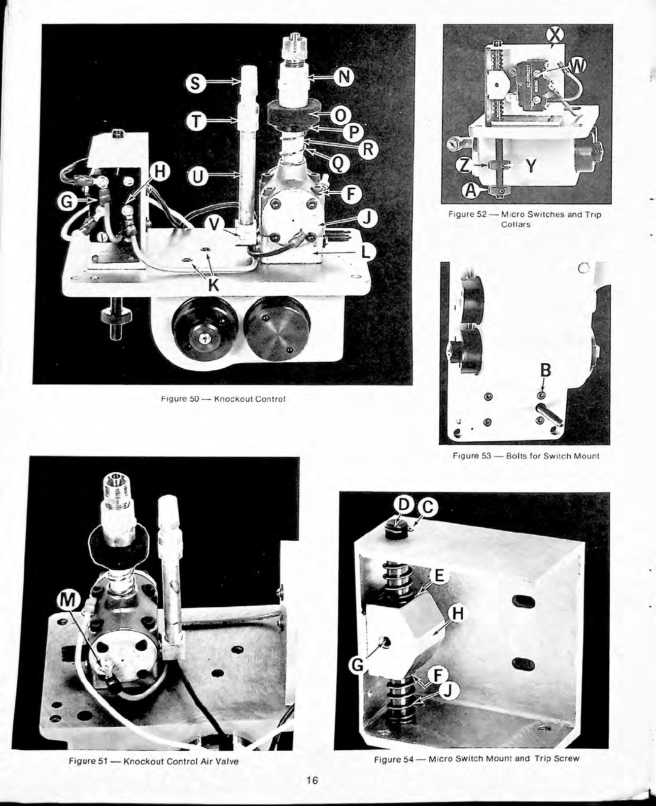
Figure
52
—
Micro
Switches
and
Trip
Collars
Figure
50
—
Knockout
Control
Figure
53
—
Bolts
for
Switch
Mount
Figure
54
—
Micro
Switch
Mount
and
Trip
Screw
Figure
51
—
Knockout
Control
Air
Valve
16
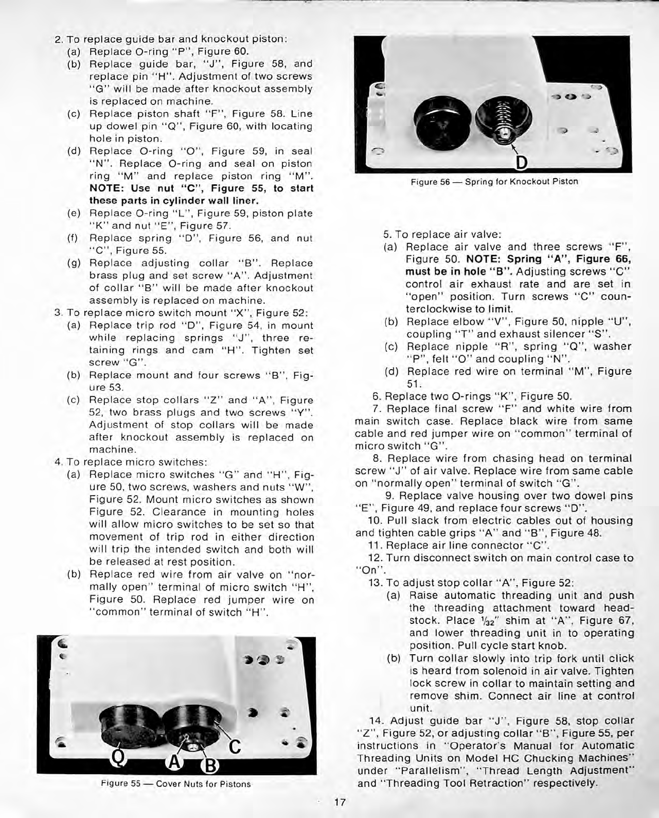
2.
To
replace
guide
bar
and
knockout
piston:
(a)
Replace
O-ring
“
P
”
,
Figure
60.
(b)
Replace
guide
bar,
“
J
”
,
Figure
58,
and
replace
pin
“
H
”
.
Adjustment
of
two
screws
“
G
”
will
be
made
after
knockout
assembly
is
replaced
on
machine.
(c)
Replace
piston
shaft
“
F
”
,
Figure
58.
Line
up
dowel
pin
“
Q
”
,
Figure
60,
with
locating
hole
in
piston.
(d)
Replace
O-ring
“
O
”
,
Figure
59,
in
seal
“
N
”
.
Replace
O-ring
and
seal
on
piston
ring
“
M
”
and
replace
piston
ring
“
M
”
.
NOTE:
Use
nut
“
C
”
,
Figure
55,
to
start
these
parts
in
cylinder
wall
liner.
(e)
Replace
O-ring
“
L
”
,
Figure
59,
piston
plate
“
K
”
and
nut
“
E
”
,
Figure
57.
(f)
Replace
spring
“
D",
Figure
56,
and
nut
“
C
”
,
Figure
55.
(g)
Replace
adjusting
collar
“
B
”
.
Replace
brass
plug
and
set
screw
“
A
”
.
Adjustment
of
collar
"B
”
will
be
made
after
knockout
assembly
is
replaced
on
machine.
3.
To
replace
micro
switch
mount
“
X
”
,
Figure
52:
(a)
Replace
trip
rod
“
D
”
,
Figure
54,
in
mount
while
replacing
springs
“
J
”
,
three
re
taining
rings
and
cam
“
H
”
.
Tighten
set
screw
“
G
”
.
(b)
Replace
mount
and
four
screws
“
B
”
,
Fig
ure
53.
(c)
Replace
stop
collars
“
Z
”
and
“
A
”
,
Figure
52,
two
brass
plugs
and
two
screws
“
”
.
Adjustment
of
stop
collars
will
be
made
after
knockout
assembly
is
replaced
on
machine.
4.
To
replace
micro
switches:
(a)
Replace
micro
switches
“
G
”
and
“
H
”
,
Fig
ure
50,
two
screws,
washers
and
nuts
“
W
”
,
Figure
52.
Mount
micro
switches
as
shown
Figure
52.
Clearance
in
mounting
holes
will
allow
micro
switches
to
be
set
so
that
movement
of
trip
rod
in
either
direction
will
trip
the
intended
switch
and
both
will
be
released
at
rest
position.
(b)
Replace
red
wire
from
air
valve
on
“
nor
mally
open
”
terminal
of
micro
switch
“
H
”
,
Figure
50.
Replace
red
jumper
wire
on
“
common
”
terminal
of
switch
“
H
”
.
D
Figure
56
—
Spring
for
Knockout
Piston
5.
To
replace
air
valve:
(a)
Replace
air
valve
and
three
screws
“
F
”
,
Figure
50.
NOTE:
Spring
“
A
”
,
Figure
66,
must
be
in
hole
“
B
”
.
Adjusting
screws
“
C”
control
air
exhaust
rate
and
are
set
in
“
open
”
position.
Turn
screws
"C
”
coun
terclockwise
to
limit.
(b)
Replace
elbow
“
V
”
,
Figure
50,
nipple
“
U
”
,
coupling
“
T
”
and
exhaust
silencer
“
S
”
.
(c)
Replace
nipple
“
R
”
,
spring
“
Q
”
,
washer
“
P
”
,
felt
“
O
”
and
coupling
“
N
”
.
(d)
Replace
red
wire
on
terminal
“
M
”
,
Figure
51.
6.
Replace
two
O-rings
“
K
”
,
Figure
50.
7.
Replace
final
screw
“
F
”
and
white
wire
from
main
switch
case.
Replace
black
wire
from
same
cable
and
red
jumper
wire
on
“
common
”
terminal
of
micro
switch
“
G
”
.
8.
Replace
wire
from
chasing
head
on
terminal
screw
“
J
”
of
air
valve.
Replace
wire
from
same
cable
on
“
normally
open
”
terminal
of
switch
“
G
”
.
9.
Replace
valve
housing
over
two
dowel
pins
“
E
”
,
Figure
49,
and
replace
four
screws
“
D
”
.
10.
Pull
slack
from
electric
cables
out
of
housing
and
tighten
cable
grips
“
A
”
and
“
B
”
,
Figure
48.
11.
Replace
air
line
connector
“
C
”
.
12.
Turn
disconnect
switch
on
main
control
case
to
“
On
”
.
13.
To
adjust
stop
collar
“
A
”
,
Figure
52:
(a)
Raise
automatic
threading
unit
and
push
the
threading
attachment
toward
head-
stock.
Place
1
/
32
''
shim
at
“
A
”
,
Figure
67,
and
lower
threading
unit
in
to
operating
position.
Pull
cycle
start
knob.
(b)
Turn
collar
slowly
into
trip
fork
until
click
is
heard
from
solenoid
in
air
valve.
Tighten
lock
screw
in
collar
to
maintain
setting
and
remove
shim.
Connect
air
line
at
control
unit.
14.
Adjust
guide
bar
“
J
”
,
Figure
58,
stop
collar
“
Z
”
,
Figure
52,
or
adjusting
collar
“
B
”
,
Figure
55,
per
instructions
in
“
Operator's
Manual
for
Automatic
Threading
Units
on
Model
HC
Chucking
Machines"
under
“
Parallelism
”
,
“
Thread
Length
Adjustment
”
and
“
Threading
Tool
Retraction
”
respectively.
Figure
55
—
Cover
Nuts
for
Pistons
17
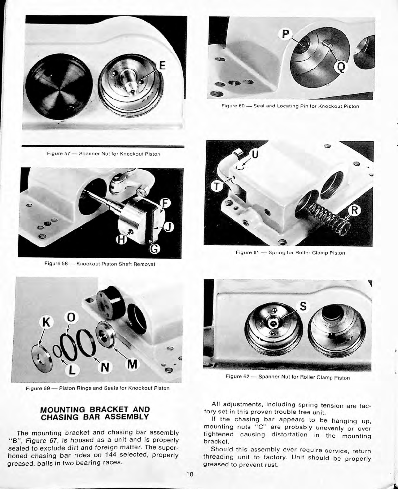
Figure
60
—
Seal
and
Locating
Pin
for
Knockout
Piston
Figure
61
—
Spring
for
Roller
Clamp
Piston
Figure
58
—
Knockout
Piston
Shaft
Removal
Figure
62
—
Spanner
Nut
for
Roller
Clamp
Piston
Figure
59
—
Piston
Rings
and
Seals
for
Knockout
Piston
All
adjustments,
including
spring
tension
are
fac
tory
set
in
this
proven
trouble
free
unit.
If
the
chasing
bar
appears
to
be
hanging
mounting
nuts
“
C
”
are
probably
unevenly
tightened
causing
distortation
in
the
mounting
bracket.
Should
this
assembly
ever
require
service,
return
threading
unit
to
factory.
Unit
should
be
properly
greased
to
prevent
rust.
MOUNTING
BRACKET
AND
CHASING
BAR
ASSEMBL
up,
or
over
The
mounting
bracket
and
chasing
bar
assembly
“
B
”
,
Figure
67,
is
housed
as
a
unit
and
is
properly
sealed
to
exclude
dirt
and
foreign
matter.
The
super-
honed
chasing
bar
rides
on
144
selected,
properly
greased,
balls
in
two
bearing
races.
18
Other Hardinge Industrial Equipment manuals


